Thursday, March 30, 2006
First polypropylene extruded...
Interestingly, an extruder tip orfice that was yielding approximately 3 mm filament for CAPA is yielding 5 mm filament for polypropylene.
Another hopeful effect was that most of the contact points between different parts of the filament aggregation were thermally welded together. Not all were, though.
This evening I ran another exercise with polypropylene at 165 degrees Celsius and a slower, more controlled extrusion rate. Although the filament quality was still poor, it ran at a diameter of about 3.15 mm. It was also warm enough that it did not tend to tangle as it did with the first experiment. The melting point of polypropylene is listed in the literature at 170 Celsius. One usually expects the working temperature of the polymer to be considerably higher than its melting point.
 Oddly, while more force was required to create a filament than was the case with filled CAPA polymer it was not an excessive amount of force.
I suspect that polypropylene is about the highest temperature polymer that it might be possible to use in a reprap. My worry is that an extrusion thread will cool too quickly to weld onto previous layers in a room temperature environment.
It would be fun and informative to see if a Mk II could produce the temperatures necessary to melt a polypropylene filament and whether we could prototype with this polymer.
One thing to remember about polypropylene is that it won't melt on a hot day or if you spill your tea on it. It also costs 35% of what CAPA does. That's why I keep looking at it. :-)
Wednesday, March 29, 2006
Potential support material...
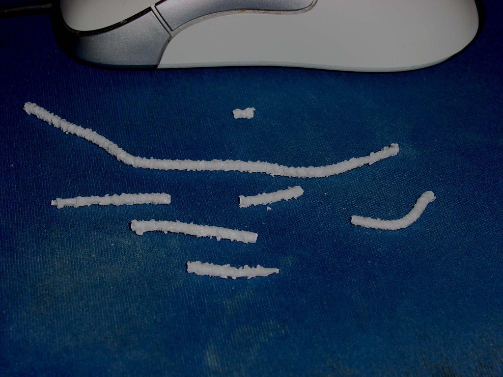
The resulting filament was spiky and rough to the touch. I am guessing but suspect that the spikes are pockets of marble dust. I would need a microscope and coloured CAPA to be certain.
After it cooled the filament could be broken with minimal bending. It was very fragile and as a support material would be perfect. It may be that we have to use this support material in rod form unless we want to use a little more CAPA in the mix. We can extrude it using retail marble dust for US$4.30/kg and US$2.50/kg for marble dust in 20 kg bags.
I suspect that the surface treatment of the filament would be better if the filler and polymer were more thoroughly mixed than I was able to do with a bamboo stick. It might be that we could get a filament that we could coil if we did that, too.
Just as a side issue, I had my first RepRap research accident with this experiment. I forgot to seat the cartridge heater in the extruder barrel before turning on the system. The cartridge heater was sitting on top of a piece of scrap poplar. I went back to my PC for a few moments to let the extruder barrel heat up and, when I detected the odor of toasted poplar, got up to make the extrusion. I found that the cartridge heater had charred its way through about 5 mm of poplar and had a cheery little flame started on it where it lay on the table. About 75% of the cartridge heater had reached orange, not red, hot.
I shut down the electricity figuring that I had ruined the cartridge heater. After it cooled, I seated it in the extruder barrel and turned it back on. Amazingly, it worked perfectly. I have a whole new appreciation for ISM heating elements' robustness.
Tuesday, March 28, 2006
Ridiculous... :-/
The filament is beautiful. The dirty barrel nastiness cleared out in the first 5 cm of filament and the rest was pretty clean. There was a bit of blistering on the surface of the filament, but nothing that would affect its usefullness. I extruded at about 95-100 degrees Celsius.
This method could turn CAPA into filament at roughly a kilogram per hour. That's just shy of a half-kilometer of filament every hour. We don't need nearly that sort of capacity to make a go of this.
I wonder if I can do this with CAPA granules. They're a dollar/kg cheaper than powder and a lot less messy.
Serendepity strikes again...
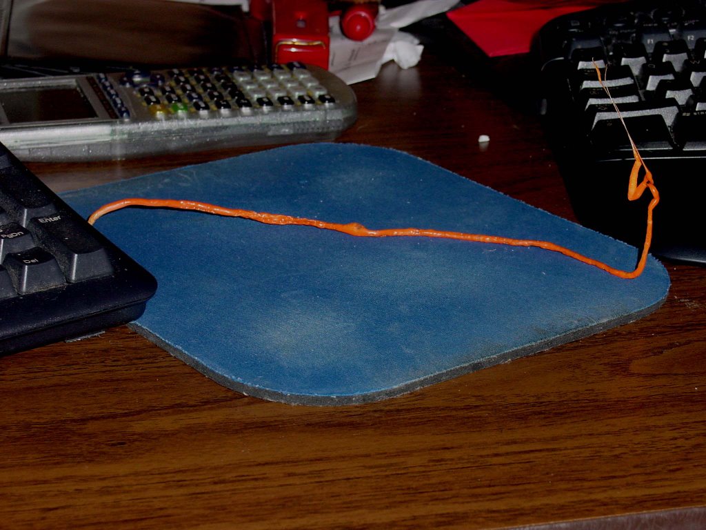
Anyhow, here goes. I had to drill out the extruder barrel to get the marble dust/CAPA mix clear of it this morning. It was quite a mess to say the least. This afternoon I thought about running that mix through the polymer pump again and sort of wilted at the thought. I thought about those push filament through with your hand experiments in the archive. I took the cleaned extruder barrel, insulated it with two scraps of poplar wood, filled it up with the marble dust/CAPA mix and kicked on the cartridge heater. In 2-3 minutes the IR thermometer said that it was nearing 100 degrees Celsius, so I inserted a .25-inch rod into the barrel and gave the charge a tentative push. I estimated that I applied about 10 lbs of thrust which put the cartridge barrel at about 14-15 atm. I emptied the barrel in about 5-10 seconds of steady pushing.
I got a 300 mm long filament out of that which was a uniform 3.175 mm in diameter. Because of the lower temperature and possibly the filler the filament was self-supporting. I caught the filament in a cup of cold water. Here it is. The colour is nasty because I didn't finish the drillout with an alcohol swabbing.
The filament was straight coming out but got bent and twisted in the small cup of water.
What I did here reminds me more than a little of Adrian's bicycle pump filament maker idea. The filament that resulted is quite flexible and more than a little like Weedeater cord in feel.
This mix is 40% calcium carbonate by volume and roughly 60% calcium carbonate by weight.
If this mix produced a usuable filament in the Mk II it would bring the cost of extrusions down from US$12.73/kg to US$8.52/kg. I suspect that if we bought marble dust in 20 kg sacks like we will the CAPA that our mix price would drop to somewhere in the vicinity of US$7.73/kg.
The quality of the filament and the ease and speed of it's manufacture has got me to thinking about the notion of a reciprocating piston extruder again. Brett brought up something like that in a discussion we had some weeks ago. Hmmm...
LOL! :-)
Monday, March 27, 2006
New stripboard layout for bipolar controller tested

Looks like I didn't make too many mistakes on the layout. Seems to work quite nicely with the NEMA 17.
I still have to stack another 754410 on the one there and add a heatsink to it.
Sunday, March 26, 2006
First filament extrusion run with added filler...
Saturday, March 25, 2006
Godzilla comms board just about done...
That's all right though. Looking at the extruder controller that Simon and Vik have got rolling now I'm going to need a few extra ! uF electrolytic capacitors for that in any case, so it's off to Potter's in the morning. :-)
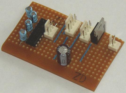
I decided to star 5v and 12 v power to each board instead of trying to put power lines in the token ring communications cable. That simplifies the board a bit in that I don't try to convert 12v power into 5v power on the board with a 7805. It also lets me use 2 pin screw terminals instead of the the larger ones on the layouts in the documentation. This board requires only 5v power which is supplied through the screw terminal on the nearest edge of the stripboard in the pic. The incoming and outgoing connections to the token ring are in the middle of the board in the approximate locations shown on the strip board layouts. I spread things out a bit so that I didn't have those electrolytic capacitors bumping into the legs of the MAX232. I also had to move a few jumpers over a few tracks to make room for a bit bigger than usual 100 uF capacitor. Strip board is very nice about letting you get away with that. :-)
Friday, March 24, 2006
Networked Extruder Board in Alpha Release
http://reprapdoc.voodoo.co.nz/bin/view/Main/BuildingAStripboardExtruderController
If anyone spots any bugs, please let me know.
Vik :v)
ARNIE finds her feet
It'll be a good week or so before she'll be up and running. Each of the z-bed's 4 sections takes 25hrs to build on the Strat...
Thursday, March 23, 2006
Retiring the electric screwdriver...
- the extruder system had been thoroughly cleaned
- the batteries in the electric screwdriver had been charged overnight
- the electric screwdriver was set for maximum torque
- a chronometer was available
- a more orderly way of keeping the polymer hopper filled using the funnel rather than a spoon had been tested
- the extruder barrel was set to 130 degrees Celsius
- the quenching bath was set to 60 degrees Celsius (it declined to 50 degrees over the course of the exercise
The extrusion exercise lasted 00:10:59. For the first 4-5 minutes I would estimate that over 75% of the extrusion took place. After that the electric screwdriver slowed down dramatically as the batteries discharged. There was not a linear dropoff in rotational speed. Effectively there were two rotational regimens, viz, full speed and very slow with a transition period of less than a minute. I tried to hand turn the auger when this happened and did not observe any meaningful increase in resistance to turning. The battery pack also heated up to the point where it was hot when a hand was applied to the body of the screwdriver.
After 00:11:59 the electric screwdriver stopped altogether. There was still no untoward resistance to hand rotation of the auger. The batteries discharged state seemed to explain the stoppage, not a change in conditions inside the extruder. This was not obvious in earlier tests of much shorter duration.
Initially in the exercise as the polymer pump filled the extruder barrel there was a quite substantial reverse thrust that tried to push the auger out of the pump. I couldn't estimate the amount of force required to keep the auger in the pump but can only say that it was substantial in that I had to work hard to return the auger to its proper position. After the extrusion started I no longer had to apply any force force to the auger through the electric screwdriver to keep it where it belonged. This situation lasted perhaps half a minute.
A few observations about the filament in the quenching bath. The filament...
- stayed transparent indicating that it was molten
- stayed on top of the quenching bath via surface tension, when poked with a bamboo stick it sank
- tried to adhere to the pyrex glass bottom of the quenching bath when it contacted it
I teased the filament around the boundaries of the pyrex quenching bath with a bamboo stick and kept it in once piece even after I removed it from the bath. The semimolten state of the filament caused it to stretch in a few places when I handled it during the transfer, however.
This exercise yielded roughly 680 mm of filament exhibiting a diameter of 2.9-3.15 mm. Approximately 4.9 cm^3 of polymer was extruded during the 00:10:59 of the exercise That is enough to supply a Mk II for approximately 01:45:00 of operation. Interestingly, there was a very slight discolouration of the filament for the first very few mm of extrusion after which the filament exhibited the waxy white colour of the CAPA 6800 granules.
One interesting observation was that the extrusion contained air bubbles at times when it left the extruder tip. These expanded and popped with a quiet little crackling noise The molten state of the filament at this point healed any distortion in the filament that these bubbles caused leaving a very nice, solid filament.
 It has become quite obvious that the electric screwdriver is useful only for proving the concept of a filament extruder and that continued running of it at these loads and for these durations will eventually ruin it. For that reason I am discontinuing its use in filament extrusion experiments while it still functions as an effective electric screwdriver. I ordered in its place last night a much more powerful Siemens 12v gear motor rated at 3 amps which is used to operate electric windows. It has a maximum rotational speed of just under 60 rpm which is in the same range as the screwdriver and over 20 times the torque output of the electric screwdriver. The Siemens gearmotor should give much better service for extended operation. It was less expensive than the electric screwdriver.
I am postponing further filament experimentation until the new gear motor arrives.
Some hours later I broke the extruder down and cleaned it. I encountered the usual polymer melt that extended through the PTFE thermal barrier and 23 mm into the polymer pump barrel. The photograph of the polymer melt clearly shows the transition from fully melted polymer to barely consolidated polymer powder.
 It seems apparent now that the vast majority of the thermal energy causing these melts is migrating up the shaft of the auger bit from the heated extruder barrel chamber. Interestingly, the distance into the polymer pump that the melt extended during the current 11 minute extrusion exercise seems to be about the same that was observed with extrusion exercises lasting only a very few minutes. I am looking forward to doubling the extrusion time when the new gear motor arrives and seeing if what happens with the melt length under those conditions.
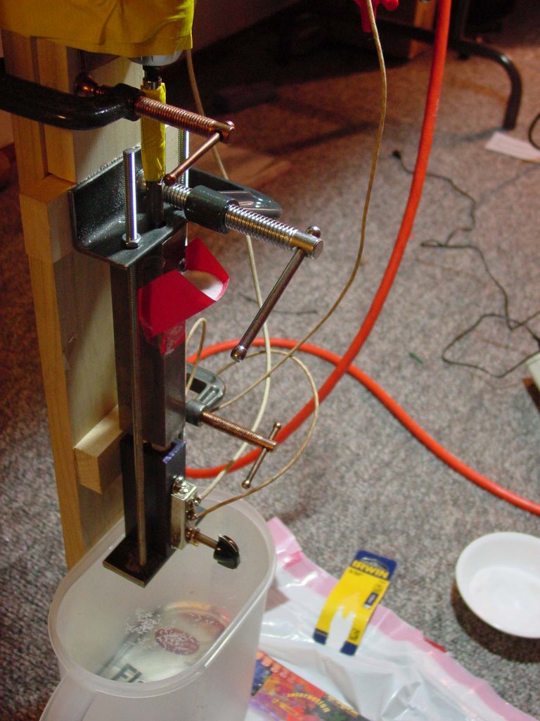
A workable coupling for the filament extruder
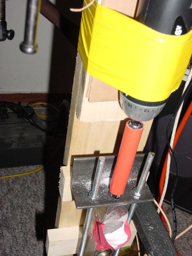 That provided a perfect friction fit for the 10.4 mm bit shank and the extender for the electric drill. I didn't even have to use the hose clamps that I had bought to go with it. This joint didn't slip under any circumstances.
I set up to do a filament extrusion test with a 58-60 Celsius quenching bath. Unfortunately, I'd neglected to put a full charge on the electric drill, so it ran much slower than usual which meant that I had a very uneven extrusion rate. All the same, the filament production even under these adverse circumstances was quite good.
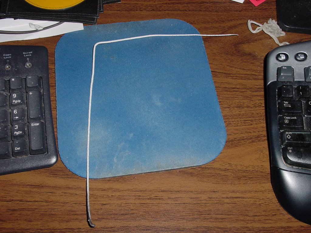
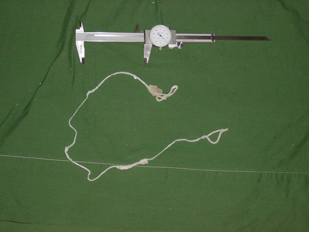
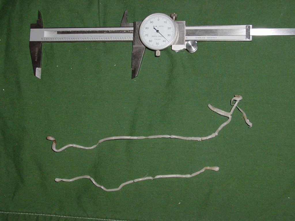 This time I teased the filament out into straight sections with a bamboo stick. In the pic the calipers are opened to 100 mm for scale.
I got an irregular extrusion rate that meant that diameter control wasn't so good this time. Tomorrow I will try it again with a full battery charge and see what happens. If that's good I'll start looking at some marble dust filler mixes to see what goes on with extruding filled polymer.
Wednesday, March 22, 2006
Making the quenching bath be the takeup reel...
You make your quenching bath out of circular pan, put it on a Lazy Susan and rotate it. Keep the water temperature in it at 58-60 degrees Celsius. Locate the extruder tip near the wall of the rotating bath.
The filament will be forced out towards the edge of the bath and eventually touch it. That will straighten it out and keep it pressed close to the rotating wall of the bath. As the filament lengthens, being slightly heavier than water, it will fall to the bottom of the bath right by the wall.
Viola! After a few hours you turn off the filament extruder and you have a coil of filament lying in the bottom of the bath.
I'll bet you that that works just fine. Orchard supply has just the right sized Lazy Susan that turns on a raceway of ball bearings for about US$8 for the diameter that will be needed.
I just LOVE the bazaar model of technological problem solving! :-D
Tuesday, March 21, 2006
Getting the filament out of the bath...
Brett said...
The alternative, of course, is to draw the tempered fillament down through a tapered die, like drawing wire. If that die is kept cold, it will skin the fillament over, and then you just have to take care not to draw it so fast that you overrun the extruder.
We've got to have a hands-off filament maker or we will drive ourselves crazy making filament to keep the repraps fed. We've pretty much solved the problem of extruding the filament on a small scale and we know that we can quench the filament in a water bath.Then what? Right now we have filament that looks like squiggles. We know that we can heat the quenching bath and keep the filament pliable. Now, how do we get it out of the bath and onto a takeup reel.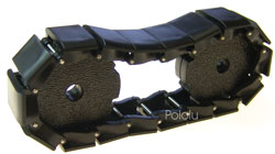
How about if we put something like this just under the surface of the quenching bath water. The extruding filament is just ever so slightly heavier than water, so if we have a conveyer like this that is under water at the extruder tip and comes just out of the water at the other end of the bath and if we ran it at about the rate that the filament was coming out of the extruder tip with a little experimentation we just might be able to tease the filament onto a takeup reel.
Brett's notion of a tapered die can take the form of a pair of chute walls that progressively narrow the path that the filament can take. The warm water keeps the filament pliable and the gentle force applied by the conveyer straightens it.
Rather than wasting a lot of time designing this sort of system and making it with the Stratasys machine, better to buy one from these guys.
http://www.pololu.com/products/misc/0415/
They've got all the bits for doing this made from ABS, so I can find out if the concept works without having to face the problem of how to make something from CAPA which will soften in the quenching bath.
Joints that don't break...
I drove across town to Seaside to a large art supply shop to see if I could acquire some marble dust to use as filler. When I got there I discovered that both that shop and the much smaller art supply shop about less than two km from my flat are both owned by the same person. The smaller shop hard by my flat had the marble dust, of course. :-p
Quenching baths for CAPA
It appears that the bath temperature where CAPA remains pliable yet has enough tensile strength to hold together is somewhere in the range of 58-60 degrees Celsius. Get any higher than that and the filament comes apart. Get any lower and it is unworkable.
It would appear that a thermostat/heater system with a pretty narrow deadband is going to be required for the quenching bath. :-(
Sunday, March 19, 2006
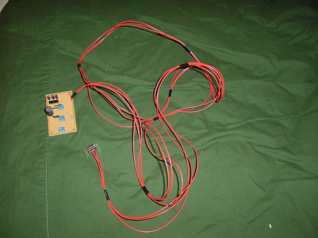
New cable wiring and connectors
Pictured is the current design of the main interface board that I put together this morning. During the rebuilds I have also switched to a different type of connector. I think these should be fairly readily reprappable and they do a good job of preventing you from putting things in backwards. They're also moderately cheap.
Saturday, March 18, 2006
Continued filament extrusion experiments.
 This evening I made another extrusion test. This time I began with a thoroughly cleaned extruder assembly and used a quenching bath heated to about 55 degrees. The extruder barrel was heated to 120 degrees. CAPA 6406 was used.
As you can see in the picture the first few centimeters of extrusion was darkly coloured. Interestingly though after that the filament was a uniform white very much the same colour as the CAPA 6800 pellets.
Filament diameter varied between 2.9 and 3.2 mm. Approximately 450 mm of filament was extruded which weighed 3.6-3.8 grams in a matter of a few minutes.
Using the heated quenching bath changed the nature of the extrusion filament dramatically. This filament was flexible. As well, the warm water was much more forgiving of irregular extrusion rates. No serious weakpoints in the extruded filament were observed.
One change that wants making in the version 2 extruder is a different feed arrangement. Version one was designed to be operated in a horizontal position. This creates flow problems for the polymer powder into the feed chamber.
Afterwards, I cooked off the extruder barrel and removed the auger. The auger was covered with melt for the length of the PTFE thermal barrier. There were a few small bits of partially molten polymer powder in the feed barrel near the PTFE thermal barrier. Similarly, there was a bit of molten polymer powder at the end of the PTFE barrier on the extruder barrel side. These "bits" were a few mm in length and width and perhaps half a mm thick.
Clearly, the CAPA tube that had formed in PTFE barrel had done so over several operating cycles.
Right now the length of operation of the extruder is dependent on the time that it takes the duct tape joint between the electric screwdriver and the auger to fail. It will be interesting to create a joint which will not break and then let the extruder pump clean itself to see if that makes cleaning the system easier.
Friday, March 17, 2006
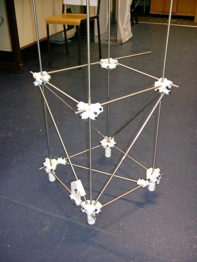
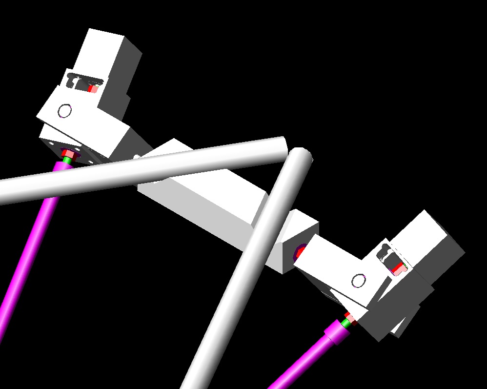
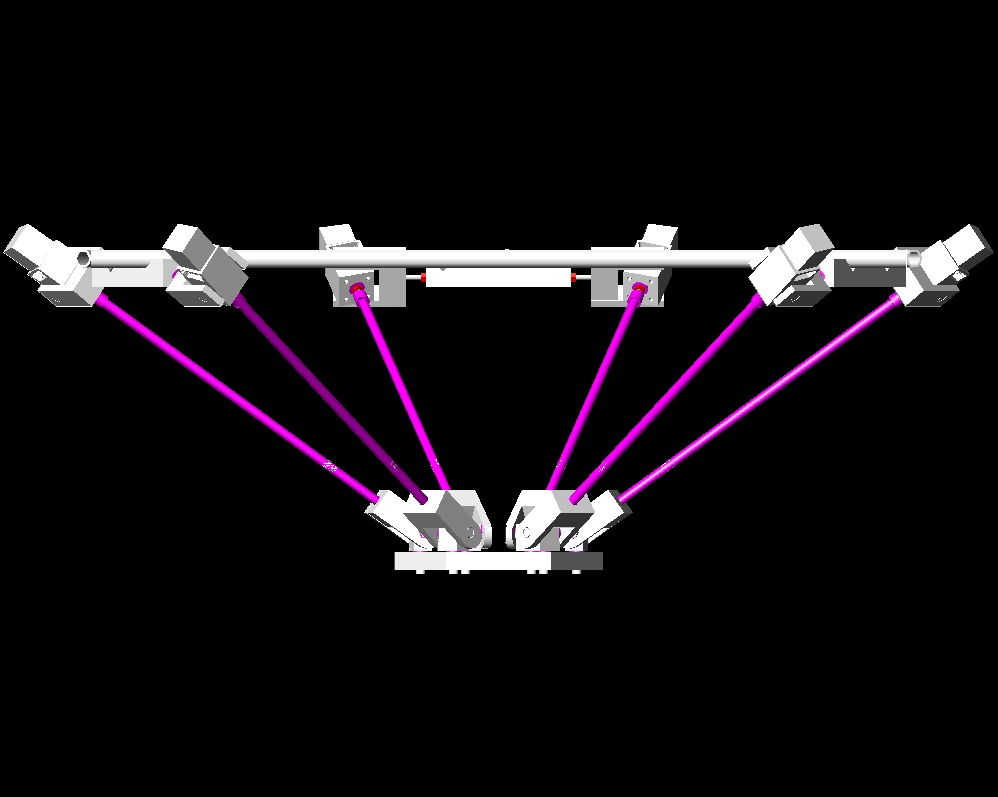
Stewart platform, Rev 1.
platform. Aside from machining the stepper mounts, (2 complete, 4 in progress) I've been modeling up the assembled platform, to get a look at the geometry.
First, an over-view: The frame, (Not all shown) will consist of a space frame with a triangular base and top. Suspended from the top triangle by pipe hangars are blocks which alow lengths of 8m1 threaded rod to freely pivot. At each end of the threaded rod are yokes which suspend the stepper mounts. At the far end of each actuator is a yoke connecting to a pivot attached to the tooling plate.
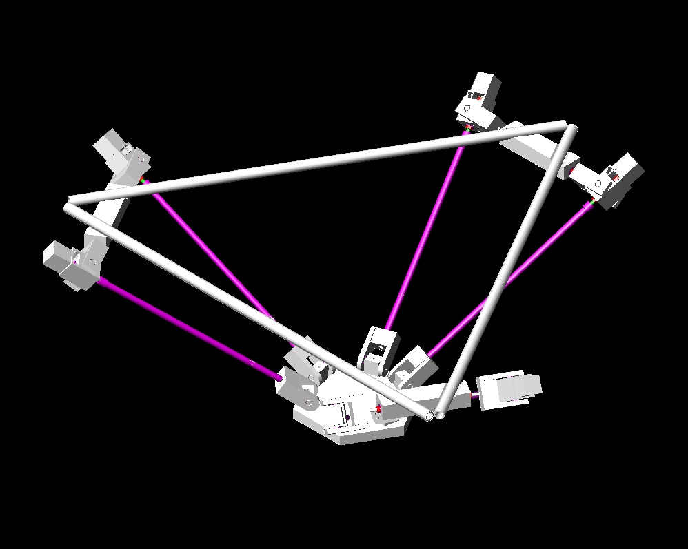
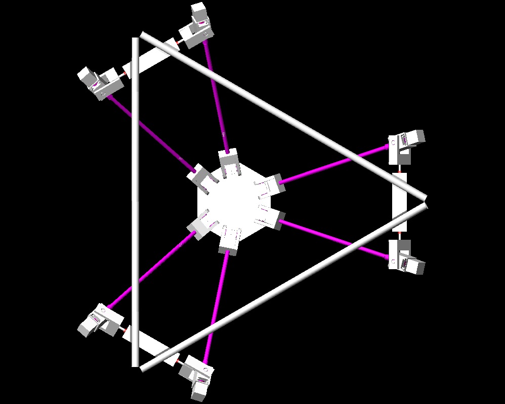
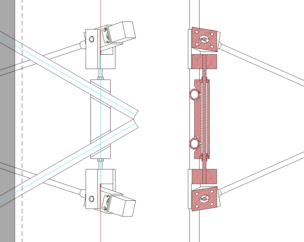
All the pivots are designed to use inline skate bearings, which are fitted around either
8m1 threaded rod, or 8mm shoulder screws.
The yoke designs are still a bit clunky, and I need to model up the extruder to confirm that it will fit, and determine what kind of tilt angles are feasible.
Tuesday, March 14, 2006
Polygon software

When you slice an STL file with a plane, the result is one (or more) polygons. These have to be filled with RP goo somehow to make a solid in layers. As we are going for FDM, this means offsetting the polygon by half the width of the stream, outlining it with goo, then offsetting again and cross-hatching to fill the interior.
I have been writing Java software to do this. I have decided to do a CSG implementation of polygons as unions, intersections, and differences of planar half spaces (i.e. you treat an infinite straight line as being solid on one side and air on the other so, for example, if you intersect three such you make a triangle).
The reason for this is that, compared to the more obvious solution of storing a linked list of line segments between vertex points, once you've got it working it makes polygons that are guaranteed never to self intersect, are easy to offset correctly, and can themselves be easily combined using boolean operations. The downside is that you have to turn the original slice into a CSG form from what is basically an unstructured bunch of line segments that may join up if you're lucky. Fortunately there's an algorithm for that - Tony Woo's alternating sum of volumes algorithm. Implementing that is my next task.
The picture above shows a test polygon, and the result of offsetting it. If you increase the offset, it all behaves nicely, and automatically avoids lines crossing each other:

Cross-hatching for infill is fairly easy. Here's an inner and outer polygon, both offset, then the result cross-hatched:
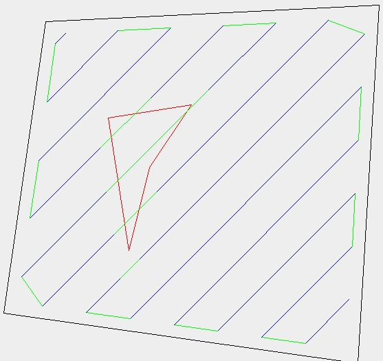
Though I haven't finished that yet - it detects the region in the middle to avoid (different colour), but doesn't link up neatly around it to minimize pen-off-the-paper moves.
How do we do a whole 3D object?
Well, Java3D will read STL files. We slice them from the top down in layers. Imagine that you're at layer N, and the next layer up where you were before is layer N-1. If U is union, - is set difference, PN is the polygon now (at layer N), and PN-1 is the one above, then:
- Get slice PN.
- Fill PN with build material.
- Fill PN-1 - PN with support.
- PN <- PN-1 U PN.
- N <- N + 1.
- If not off the bottom, go to 1.
That defines exactly what needs to happen right the way from the top to the bottom. You work it all out, then play it in reverse from the bottom to the top. This is all particularly simple if U and - are trivial operations, which they are in my implementation. Offsetting is pretty simple too, so things like being able to build slight overhangs without support can easily be accomodated by replacing Step 4. with:
4. PN <- O{(PN-1 U PN), -shrink}
where O{set, distance} is the offset function, and shrink is the width of the overhang that can be sustained.
Job done...
First Microchip PIC16F628 for Godzilla project programmed...
I built the JDM PIC chip programming board more than a month ago, but just got around to trying to program a 16F628 chip on it this weekend. This is an important thing to be able to do because the 16F628 is the core of all the controller boards for the Godzilla prototyping machine. Simon, Vik and Adrian have been moving towards a final design for all the boards for the past month and it is looking like I'll be able to start building them in a week or two.
Anyway, the first bit of drama was finding the proper software to drive the board and program the 16F628's. As usual it was right in front of my nose and Simon kindly showed me the link. He then told me the settings to use to get it to work.
I plugged the board into my PC, fired up IC-Prog and had a go... nothing. For the next several hours I played chimpanzee on a keyboard trying things to see if I could get it rolling... nothing.Simon began to suspect that my ancient skills with soldering iron and PC board had maybe slipped a bit. Given that it had been 25 years since I'd last personally built one it sounded reasonable but annoying all the same. I considered just buying a premade, cheap programmer board.
Simon finally ran me through the troubleshooting protocol on the wiki site. The voltage numbers that I got made absolutely no sense whatsoever. I was going blind with fatigue when I finally crawled under my desk and had another look at the back of my PC. 25 pin cannon female connector for Com1, 9 pin cannon male connector for Com2... I'd rigged mine to use the 25 pin connector, just like the old days.Wait a minute. Where was the printer connector? In the old days we used a Centronics connector, but those had fallen by the wayside some years back and NOW we used a... 25 pin cannon connector... female. It was still confusing because when I checked mode I had 2 serial ports. If that 25 pin cannon female connector was a printer cable where the hell was the other serial coms port? I've been using USB ports for peripherals for some years now so this was all remembering how to read ancient Egyptian for me.
I finally decided that I didn't know where the other coms port was but that the one I had had to be a 9 pin male cannon connector. This morning I went down to Radio Shack and bought a 9 pin female connector. I hooked it up ran IC-prog with the settings Simon talked about yesterday.It wrote to the 16F628 and verified perfectly the first time out. I read it back into buffer 2 and compared buffer 1 and buffer 2 and it gave me a thumbs up.
Making Version 2
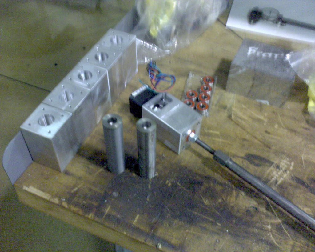
Here are the first two extruder barrels that he's fabricated. They're made of a good quality stainless steel so we should be in better shape with the colouring of the filament if my guesses about how they're getting coloured is right.
First off, version 2 will have a 1" diameter extruder barrel. The reason for this was my serendepitous discovery of a high quality, extremely cheap barrel heater used by the plastics industry in conventional extruders. 
Its a sleeve heater designed to fit over cylindrical bits of plastic extruders to keep molten polymer inside molten. This bad boy prices in at about US$6-7 for a 300 watt heater. It can be bought for either 110 v or 230 v AC mains power. The cartridge heater it replaces costs closer to US$10-15.
The only drawback to this kind of heater is that it makes the use of a bimetallic thermostat as we were able to do with version 1 impossible for the simple reason that there is no place on an extruder barrel covered by this heater to mount one. That is not a big problem in that the controller for the Mk II extruder that is being used on the RepRap itself already makes use of a thermistor temperature sensor for control. I am sending along a kit of pieces for version 2 to Simon who has kindly agreed to morph the Mk II extruder controller board design into one that can handle version 2.
The polymer pump will be made, according to Brett, from 1.25"x1.25" stainless steel bar stock.
Overall, version 2 will weigh about half of what version 1 did. This is especially important in the extruder barrel in that it will have a much smaller thermal intertia than the version 1 did. The sleeve heater should also make for a much more evenly distributed thermal input to the polymer.Results of a complete breadown of the quarter-inch extruder...
After having removed the auger and cleaned it I left the extruder barrel heater on at 120 Celsius to cook out the rest of the polymer out of the barrel. Afterwards, I disassembled the system completely.What was more interesting was the observation that polymer had not only coated the hot end of the auger but also formed a nice tube between the auger and the inside the PTFE thermal barrier.
The first thing I noticed was that the half-inch PTFE thermal barrier between the polymer pump barrel and the extruder barrel showed signs of swelling. Whether this swelling is an artifact of the heat that has been applied to the extruder barrel or the pressure that has been developed in the upper reaches of the extruder pump, or both is not known.Not only had it done that, but it had also migrated another 24 mm up the polymer pump barrel even though molten polymer had not previously been observed on the auger that far back from the extruder barrel.
Given that the system had not been broken completely down for cleaning since it began to be operated it is not clear whether this polymer tube was formed all from the get-go or later on.
Two interesting observations came from looking at this CAPA tube. First, the swelling of the PTFE barrier comes from the inside and is expressed in the tube wall thickness. Second, and even more interestingly, the tube is a clear, clean white all the way down to the end of where it exits from the PTFE barrier into the extruder barrel. Extruded CAPA, on the other hand, has been a light silver-grey. Further, there are no flakes in the tube whereas you will occasionally see a flake of dark matter in the filament.
This argues that the CAPA goes from white to silver-grey in the extruder barrel.
I'm drawing two initial conclusions.
- we are developing pressures in the extruder barrel sufficient to cause a bulging of the PTFE thermal barrier
- we are seeing either a purely thermal transformation of the CAPA colour or a thermally driven interaction between the CAPA and the mild steel walls of the extruder barrel that causes the colour change

More post extrusion filament treatment...
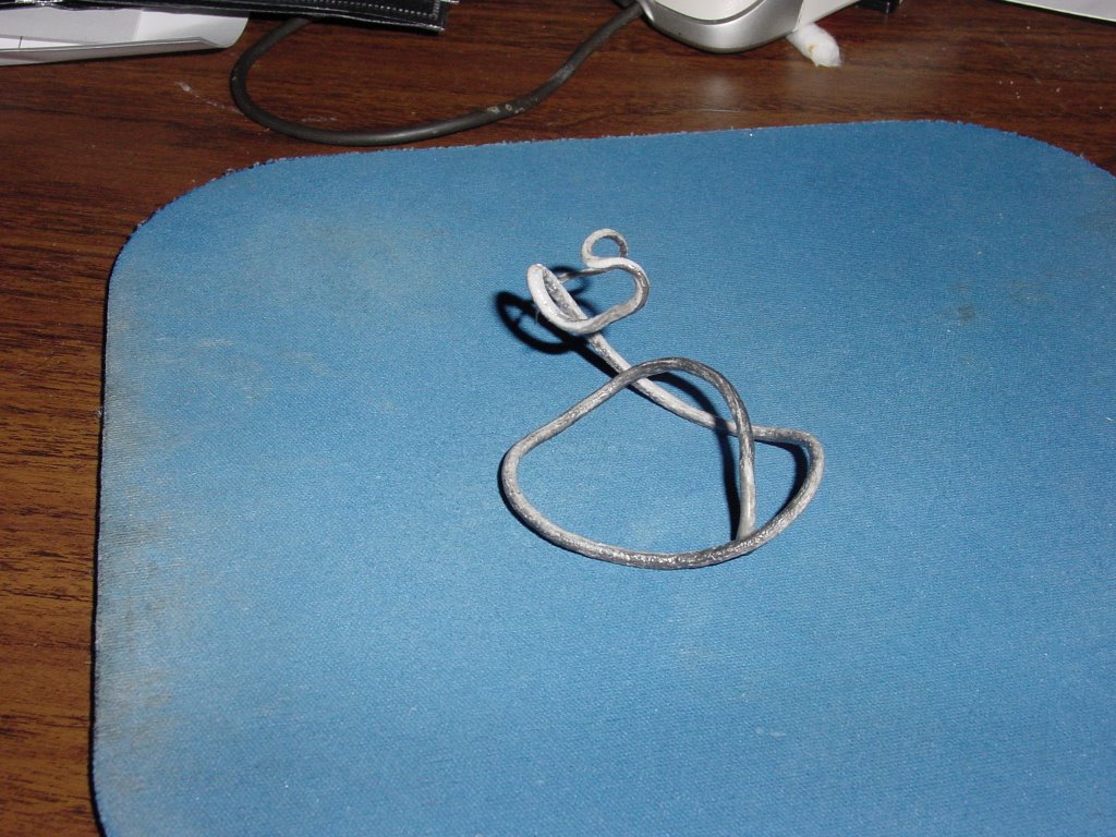
Solvay lists the melting point of CAPA at 58-60 Celsius. I created a water bath of that temperature on my stove and dumped in the filament produced with yesterday's experiment.
The filament instantly became soft and pliable. Straightening it was no problem at all, though it did break at one of the weak points where the extrusion rate had slowed down when it was being extruded.
One error in yesterday's observations was apparently in reporting that CAPA floats. Today it sank immediately, which is in keeping with it's listed density. I am wondering now whether the "floating" behaviour that it exhibited yesterday had to do with its almost neutral buoyancy coupled with the fact that it was still attached to the extruder tip.
Monday, March 13, 2006
UDN2559 Stripboard design, take 2

Circuit source (gschem) and layout source (SVG) available on request.
Vik :v)
Thursday, March 09, 2006
Closing on producing usuable filament...
The water bath was situated about 2-3 mm below the extruder tip. I heated the extruder barrel to 120 Celsius and started the system.
This was the result.

The filament emerging from the extruder was instantly quenched in the water bath. The diameter of the resulting filament varied between 3.2 and 3.9 mm. The kinks that you see occurred when I had to manually poke the polymer feed bin with a thin bamboo stick to keep it filled.
Interestingly, the filament floated. This might indicate that we are entraining air in the filament since the density of the CAPA is marginally higher than that of water. No obvious bubbles were visible, however.
The practicality of Brett's advice that we need to think about designing a polishing station to straighten and regularise the dimensions of the raw filament now becomes obvious. That should be a perfect RepRapable product.
The extruder produced about 125 mm of filament in approximately 90 seconds. For these settings that is an output level of approximately 50 cm^3/hr. I had designed the system to produce about 15 times what a Mk II could consume per unit of time. We're producing about 18 times which is very close to our design goal. I currently have no way of knowing what the duty cycle of the bimetallic thermostat was, but given the setting chosen even if the cartridge heater had been on full-time it would have had a power demand of no more than 150 watts.
What we have is a prototype that proves the concept for a small polymer extruder. We need to take the concept through several generations now to achieve a useful system. I see several developments as being needed to make this a start-and-forget system.
- an improved polymer feed hopper that makes sure that the auger receives a steady supply of resin.
- roll godets
- heating oven
- takeup reel
It would be nice if this system could be self-threading. We obviously need to design a hands-off control strategy now that we have a way of making filament. Given the work that has already been done by the team with controlling steppers and the Mk II I have no doubt that we have the talent already on board to do this.
Here is the system that we are replicating.
It costs US$85,000 used. We're going to do it for under $150 tops as best as I can see.
Wednesday, March 08, 2006
Wednesday morning tests...
This morning I did another test run of the extruder, this time with the barrel temperature set to 110. I taped down a lot of things and installed a funnel so that the feed of polymer into the pump would require less attention.
Before I powered up I noticed that the auger bit was frozen from having its tip embedded in solidified polymer in the extruder barrel. I turned on the cartridge heater as usual but this time with the extruder barrel full instead of empty. After a few minutes thermal expansion of the melting polymer forced a bit of filament out of the extruder tip before the electric screwdriver was turned on. 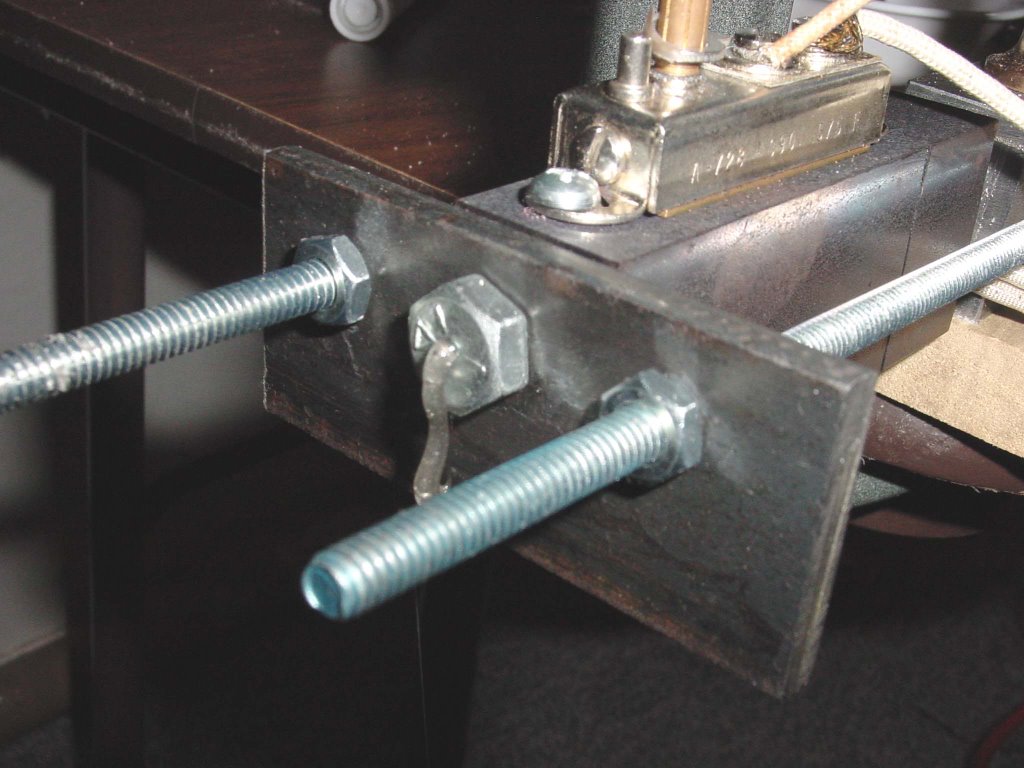 I tapped the on-button for the screwdriver and discovered that it rotated freely now.
At 110 Celsius the extrusion rate was considerably slower, but the filament tended to hold its shape better. The axial thrust on the auger bit seemed to be considerably stronger, too. The emerging filament still tends to foul on the extruder tip and thread as the length of the filament increases. Beveling the extruder tip like us done on the MK II design would be a great idea. I'll pursue that this weekend when I can get out the the drill press at my sister's house.
I took note of Adrian's experience with the filament swelling after leaving the extruder tip. The tip diameter to filament diameter proportion implied in Adrian's report was about 0.79. I worked backwards from this and determined that drilling a 3/32nds diameter hole in the extruder would result in a 3 mm filament. In practice that works out fairly close from the measurements I took this morning.
It seems obvious at this point that if we are going to extrude CAPA in this temperature range we are going to have to cool and support the filament almost immediately after it leaves the extruder tip. Otherwise it is going to draw into a thin thread because of the weight of the cooled filament end acting on the emerging polymer which, because it is molten, has a negligible tensile strength. Perhaps I can fabricate a little PTFE trough to provide that support.
08:45 PDT AKA 16:45 ZULU TIME 8 March...
It occurred to me that I had a little PTFE trough already made in the reject misdrilled bits of PTFE cylinder that I had made. I sawed one of those in half and taped it into place. You can see the result. (hmmm... pics don't seem to be uploading right now).  The filament extruded into the trough all right but promptly adhered to the PTFE surface IN the trough. It seems that drilled PTFE surfaces are quite rough, a circumstance which probably explains how we can pump polymer through the PTFE thermal barrier in spite of the fact that the friction coefficient of PTFE is so low.
 That worked to an extent but I had to be careful not to drip it on the extruder tip which chilled it and caused flow problems.
We appear to have another successful filament extruder concept...
Not to put too fine a point on it, the upgraded Mk II concept filament extruder... extrudes filament.

I decided to do the first run hot so that I could avoid problems with jamming. I set the thermostat on the heated barrel to 150 Celsius and let the system heat up for fifteen minutes keeping track of the temperature. When it hit 150 I began priming the polymer pump. Within 5 minutes molten polymer began to be extruded. I caught the output on a ceramic plate. The filament was too hot, as I expected and although it emerged with a diameter of approximately 3 mm gravity quickly stretched it thin.
 The product landing on the plate had no coherence in diameter.
Because I was working alone and was standing in for a thrust bearing for the test rig and spooning polymer into the feed chamber as the experiment was underway I was unable to photograph the extrusion as it took place.  Here is a photo of the extrusion tip after I shut the system down. You can see a thread of filament remaining on the cool tip.
The first few feet of filament was dirty with grit and grease from the machining of the barrels. That soon cleared, however, and the last filament extruded was clear. CAPA turns translucent when it cools. It feels rather rubbery and is quite strong even in thin cross sections.
In the next days I will endeavour to configure the rig so that I can operate it with hands off. I will also have to figure out a way to connect the electric screwdriver to the extruder with something a little less informal than duct tape. :-)
Interestingly, the electric screwdriver provided more than enough torque to operate the system. There was no jamming of the system for any reason. As well, I was able to manually resist the axial thrust against the screw pump. Apparently, the larger diameter extrusion orfice means that the operating pressure in the heated extruder barrel is considerably less than I expected. That is wonderful! :-D
I think as well that it would be good to slightly incline the extruder so that the filament doesn't try to hang onto the extruder tip. Having a water tray directly under it would also be a good idea. Godet stations and a takeup reel system are something that somebody might want to think about reprapping before too long.
I will also do a series of test runs at lower temperatures to find a more optimal operating regimen. I'd like to find a less informal gear motor to integrate into the system. I don't get the impression that the plastic gear motor that we use on the Mk II is going to be up to the job. I think that we will need just a little more torque than that motor can deliver. On the other hand, I get the impression that this system will produce filament at quite a good clip.
It would appear that the only reason for going to a larger diameter auger would be to be able to handle polymer in larger granules.
Using the masonry bit appears to have made all the difference at the last.
I would like to thank everybody on the team for their advice and observations. Thanks goes to Dr. Bowyer who also ran with the concept using several different assumptions and whose example prodded me to work a lot harder than I would have on my own.
Finally, especial thanks go to Vik and Brett, whose timely last minute suggestions and encouragement yesterday got me past the jamming problems that I encountered. I was very discouraged at that point. I don't think I would have attempted to run the auger through the thermal barrier and into the extruder barrel had Brett and Vik not suggested it.
Tuesday, March 07, 2006
Tests on the 6.35 mm filament extruder
There are two practical problems with doing that, though. First, PTFE is expensive at US$0.15/cm^3 (US$2.50/in^3). That wouldn't be so bad if I weren't worried that you'd be replacing it regularly because of wear between the auger and the barrel walls.
Vik makes another, more intriguing suggestion though. What if we applied a water jacket to the pumping section. My mind immediately went back to the old water cooled Browning heavy machine guns my grandfather used in WWI. I seem to remember that they worked by allowing the water to boil off. That would create a liming problem, but those are relatively easy to sort out.
Hmmm.... Adrian! How is that prototype of yours going?
20:22 PDT AKA 04:22 ZULU TIME 7 March...
Hit the hardware store again and had to choose between two German bits. One was half again longer than I needed and was made of some mad alloy of titanium and vanadium. I figured that I'd never be able to cut the carbide tip off of it, never mind mill the shank end down a bit to accomodate a thrust bushing.
I settled for a more modest German masonry bit that will require that I shorten the thermal barrier just a touch so that the tip end of it will extend into the melt chamber. I sawed off the end of that one and tested it with the pump barrel housing and thermal barrier and it happily pumps CAPA and even pumps it in the PTFE barrel. I suspect that it would have pushed the polymer completely out of the extra 25 mm of PTFE barrel beyond the end of the bit and out of the existing PTFE thermal barrier except that I was having to resist the thrust of the drill bit manually.
While I was at the hardware stockist I got the bits of power cord and taps necessary to seat the thermostat on the extruder barrel and get the melt going. I also bought a vise so that I can try drilling extruder tips here rather than having to trek out to my sister and brother-in-laws every time I need to put something in a vise.
22:35 PDT AKA 06:35 ZULU TIME 7 March...
Successfully pumped polymer through the polymer pump, through the PTFE connecting barrel and into the heated extruder chamber with the new, longer masonry bit. Set up to drill a better aligned PTFE connecting barrel in situ and marked it. Drilling awaits a more godly hour.
0623 PDT AKA 14:23 ZULU TIME 7 March...
Managed to get a true hole through a PTFE cylinder on the second try. Double checking the polymer pump test when the batteries on the electric screwdriver ran down.  Time to make some breakfast. :-P
07:05 PDT AKA 15:05 ZULU TIME 7 March...
Repeated polymer pump test with recharged batteries. Interestingly, this time the pump filled the entire heated extruder barrel, 89 mm long and .89 cm^3 volume, before jamming. The additional flights provided by the masonry bit apparently makes for a more efficient pump for the amount of torque that we have. Will be drilling an extruder tip and wiring the heater barrel after breakfast. Hope to run a full test this morning.
09:43 PDT AKA 17:43 ZULU TIME 7 March...
Thermostat and power cables rigged correctly. No fires, electrocutions or explosions so far. Have my fire extinguisher on hand just in case. :-o
Presently running tests to get a rough idea where the thermostat setpoints are. This takes time because of the thermal mass of the heater block. Taking temperature readings in the extruder mouths with the IR non-contact thermometer. The mass of the steel will predominate with this system so I don't have to run it loaded with polymer since the heater barrel weighs a couple of pounds and a full charge of polymer in the barrel less than a gram. :-)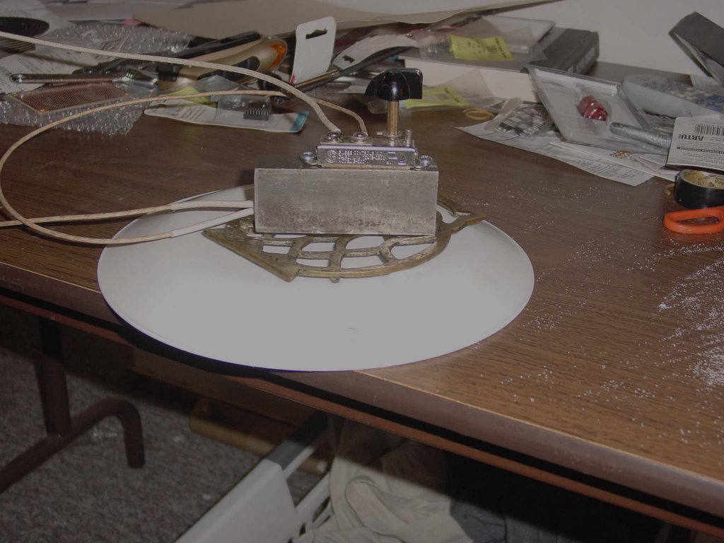
Temperature in the barrel is at about 60 Celsius just now and the thermostat setting is at 12:00.
10:16 PDT AKA 18:16 ZULU TIME 7 March...
Thermostat setting of 12:00 stabilises at 127 Celsius. Shifted thermostat to 09:00.
10:30 PDT AKA 18:30 ZULU TIME 7 March...
Thermostat setting of 09:00 stabilises at 94 Celsius. Shifted thermostat to 11:00. The indicator knob on that bad boy gets HOT!
10:58 PDT AKA 18:58 ZULU TIME 7 March...Thermostat setting of 11:00 stabilises at 116 Celsius. It looks like the thermostat is pretty linear, which is what I'd hoped for. Now, I wonder what the deadband looks like.
Adrian got a bit of extrusion going at 120 Celsius, but Solvay took their melt flow index at 160, so I'd better check to see what higher settings on the thermostat gets me. The data sheets that Jeff's people in the UK so kindly sent along with the powder samples indicates that CAPA decomposes at 200 Celsius. Fortunately, there are no halogens or nitrogen in the formula for CAPA so if I screw up and burn some it's unlikely to kill me immediately.
Oh well, now to get some food and drill a extruder tip. :-)
13:30 PDT AKA 21:30 ZULU TIME 7 March...
Thermostat setting of 15:00 stabilises at 132 Celsius. I'm going to crank the thermostat up to max, about 17:00 and see what happens.
By the way, the deadband is about 5 degrees. Not bad. :-)
13:50 PDT AKA 21:50 ZULU TIME 7 March...
Thermostat setting of 17:00 (max setting) stabilises at 160 Celsius. How convenient! :-D
Looks like I'm going to have to develop a graph for the thermostat performance. That certainly isn't linear. I also need to go back and check 15:00 again.
14:15 PDT AKA 22:15 ZULU TIME 7 March...
Thermostat setting of 15:00 (max setting) stabilises at 137 Celsius. Looks like last time I caught it at the bottom of the dead band. Ok, fair enough. :-)
So far so good! :-)
Monday, March 06, 2006
Monday tests on the 6.35 mm filament extruder
I decided to run a few preliminary tests on the 6.35 mm filament extruder before I did further work on it.
I used semolina as a proxy for polymer resin to check to see if the assembly would pump. There was no problem with that. I then inserted the PTFE thermal barrier into the assembly to see if I could pump semolina through that.
The semolina immediately jammed in the thermal barrier passage. It formed a 15 mm plug almost exactly like that I encountered when using the same auger bit in 1/4 inch steel pipe except the steel pipe only made a 5 mm plug before jamming.
The plug was easy enough to clear once I detached the thermal barrier from the polymer pump assembly.
Think that the problem might have been specific to the semolina I then used a few grams of the CAPA resin in powder form that I recently acquired as samples. The same thing happened.
Any ideas?Building the 6.35 mm filament extruder
The weather held this weekend so I was able to almost finish the 6.35 mm filament extruder prototype.
 I am using Adrian's size convention in setting the calipers open to 20 mm for scale.
You can see that it bears a close resemblance to what my design study conception looked like.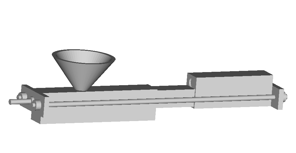
I oversized the PTFE sleeve in the thermal barrier so the design sags a bit right now. Following Brett's suggestion I will put a third support plate between the polymer pump and the PTFE thermal barrier to counteract any tendency towards buckling and more importantly, to provide a bit more support to the heavy steel extruder barrel to at the right hand side. That plate will support the retaining rods via PTFE sleeves so that heat moving down the retaining rods won't be transferred into the front of the polymer pump.
I had originally thought to use a 1 x 1 x 2 inch PTFE thermal barrier with two PTFE cylindrical plugs to connect it to the polymer pump at the left and the heated extruder barrel at the right. While I was building the extruder I realised that that would make four potential gaps in the polymer flow path between the pump and the extruder tip. I brought that down to two by drilling out a 1/2 inch cylinder of PTFE and then drilling a 1/2 inch hole in the 1 x 1 x 2 inch PTFE bar so that it acted as a sleeve for the cylinder. That worked quite nicely.
Here is a detail of the polymer pump. I got too tired to finish the thrust bushing for the auger bit so the auger is seen lying in the foreground of the pump. I am using an ordinary plastic funnel for a polymer feed hopper.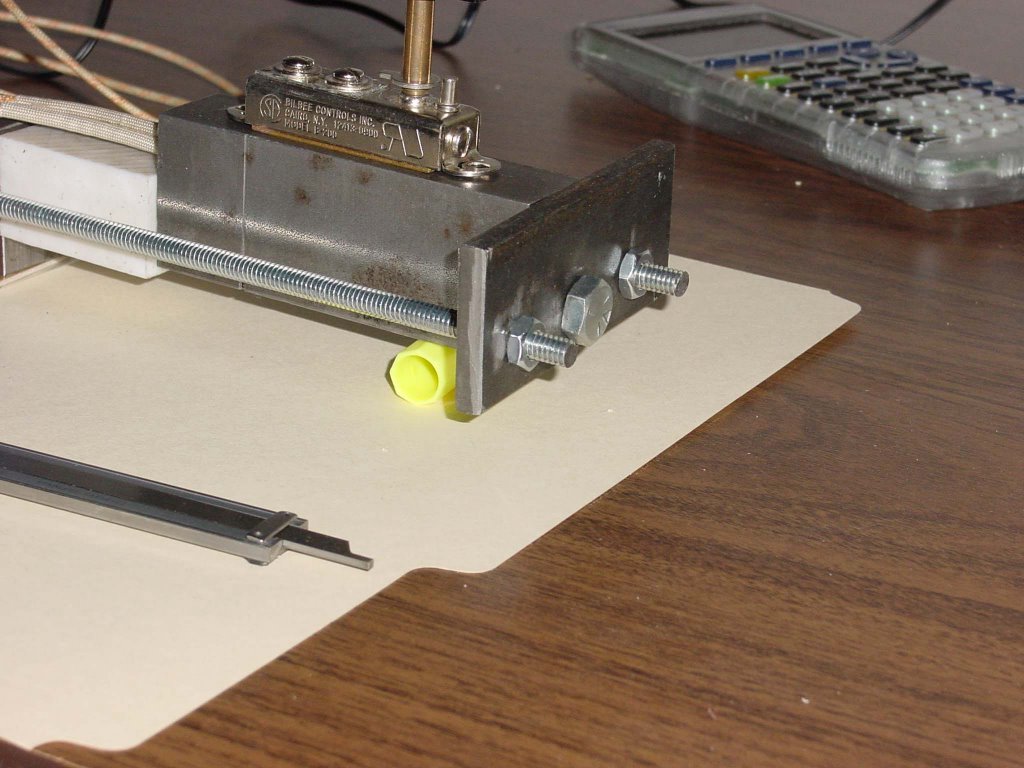
 Finally, here is a detail of the extruder block and a mockup (3/8 -24 1/2 inch bolt) of the extruder tip. Again, I was too tired at the end of the day to attempt to drill out an extruder tip. I've done trial runs on both the extruder tip and the thrust bushing, both made from 3/8 inch bolts and found that to be very finicky work. I've got a handful of the bolts so I can afford a lot of errors. :-)
You can see the wires from the cartridge heater in the photo and also the thermostat sitting atop the heated extrusion barrel.
I have to tap in the thermostat and lock the extruder down on a block. I also have to mate the shank of the auger bit with the electric screwdriver you've seen in the pictures. That all will take another morning, I expect.
It's going to be another two-tylenol night. Right now I am for some supper, a shot of MacAllan 12 year old, a movie, a hot bubble bath and a good sleep. It's supposed to begin to storm in about an hour. We've got another pineapple express storm that's come up from Hawai'i this evening.
Sunday, March 05, 2006
Electronics from Kicad and laserprinted PCBs
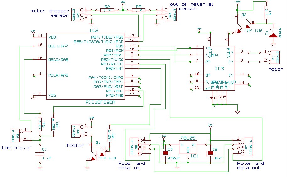
It's not too bad. After you get through the usual "How the *!$*? do I do X?" stage at the start (the manual is OK, but - of course - manuals are for wimps...) you can create schematics quite quickly. Here is a small variation on Simon's extruder controller:
That took me about an hour once I got up to speed. Kicad's automatic PCB layout tools are almost useless, but its systems to assist manual layout are very good - they are clear, and don't allow you to make mistakes. Here's the PCB for the above circuit:
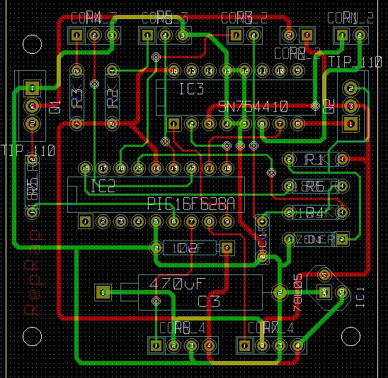
That took me about an hour too. (If you want to use Kicad install it somewhere where users will have write access to its libraries. You don't want to edit the layouts for existing chips etc., but the easiest way to add new ones is to copy and edit something similar.)
So next I decided to try to make the PCB using the laserprint-and-iron method. This wasn't such a success. I selected Kicad's high-res PCB plot option and created two postscript files, one for the reverse of the PCB and one for the obverse (component) side. The latter needs to be mirrored, of course. I then used an old HP Laserjet 6MP to print them. They came out very cleanly.
I cut the top edge of the paper on one to make them different sizes, then lined them up on a light box and taped them along the cut edge so they stayed in registration. You could probably do this almost as easily by holding them against a sunny window.
Then I cut a piece of blank double-sided PCB, cleaned it with wire wool and detergent, and taped it between the two prints.
I ironed the result on both sides. You have to take your time over this, apply plenty of heat, and be particularly thorough about the corners. The toner melts onto the PCB and sticks the paper down. You then drop it in warm soapy water and wait.
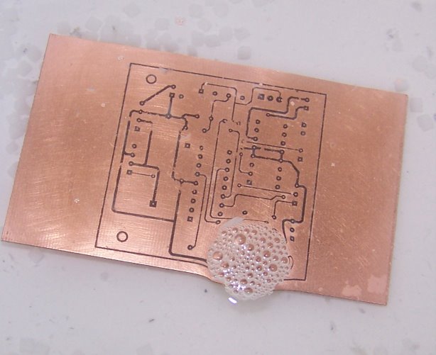
Here you need patience. If you try to rub the paper away from the toner stuck to the PCB too quickly it tears the pattern. Here's one, however, that I left for a whole day, which ought to be long enough. There are granules of polymorph in the bottom to give the soapy water access to both sides. I rubbed off the (now quite weak) paper. As you can see, the tracks still have gaps. I have tried a number of different papers, all with much the same result:
In order to avoid getting through square meters of PCB while conducting dud experiments, you need a way to clean the laser toner off. I found that 2-butanone (which I happened to have in my lab at home) worked well; this means that acetone would almost certainly do as well. Use both in a well-ventilated area, of course, and flirt but cautiously with naked flames...
Word on the web is that you need to use special water-soluble paper, which sounds reasonable. Here are a couple of suppliers:
DynaArt Designs
3535 Stillmeadow Lane
Lancaster, California 93536-6624
Phone: (805) 943-4746
FAX: (805) 943-3776
The Meadowlake Corporation
P.O. Box 497
Northport, NY 11768
I'll see if I can get some in the UK and experiment more.
More Google: other word is that the stuff to use is Press-n-peel. Opinion is divided: half the hits swear by it; the other half swear at it... I've ordered some; watch this space.
Friday, March 03, 2006
New RepRap Member
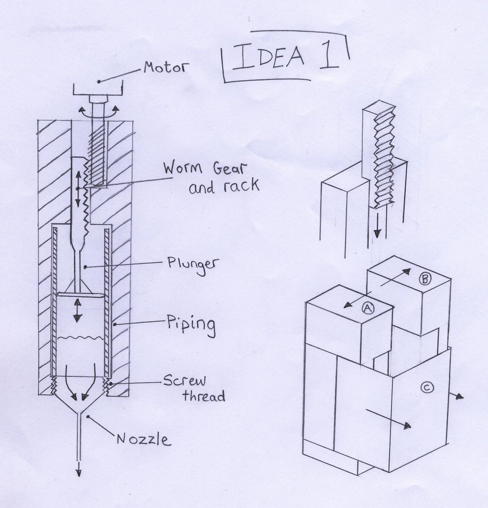
Of the three, I have decided to continue with idea 2 since it seemed the simplest and most reliable design. So now I have begun finalising the design, and will post an update when a prototype has been made and can be seen working.
UDN2559-based control board going
Now to modify the original board to use the new opto layout, and right resistor values. Then I should be able to control 2 motors. If that works I'll rearrange the bus to use the new power line arrangement Simon and Adrian figured out.
I've bought more stripboard, so hopefully I'll have 3 motors controlled soon.
It's still pretty beta so I'm not publishing yet. If anybody really wants the "how to" files though, mail me under caveat!
Vik :v)
Thursday, March 02, 2006
Design study for the 6.35 mm filament extruder
 First, I'm using a quarter-inch diameter wood auger bit that is just over seven inches long. It has eight flights in the screw for a length of four inches, two inches of bushing behind that and a shank that extends for an inch and a quarter beyond that. I didn't take time to develop the screw portion of the bit on the left on AoI and placed a thrust bearing where the bushing meets the shank on the right. The thrust bearing is made of a drilled out 3/8ths or 1/2 inch bolt.
From my previous experiments I determined that the auger should extend slightly beyond the end of the pumping section to preclude polymer packing in the pump barrel.  You can see the end of the auger extend just beyond the end of the connector plug that I've made from another one of those drilled bolts from which I've sawn off the head.
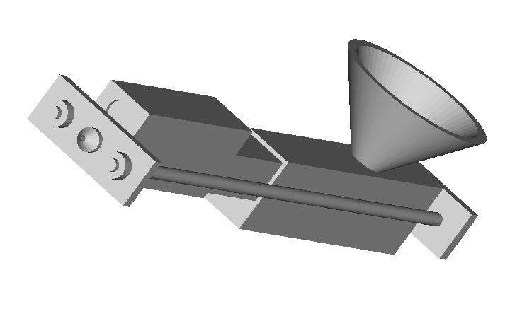
Now I include the body of the polymer pump.  You can also see the polymer feed into the top of the pump and the feed chamber where it intersects with the auger.
  Next we screw the PTFE thermal barrier onto the connector plug. I've shown the PTFE bar, which has been drilled to a quarter inch to accomodate ploymer flow and tapped at each end to accomodate the connector plugs, as slightly smaller in cross section than it is so that you can see where the steel polymer pump section and the PTFE thermal barrier join.
We can now screw the heated extruder barrel onto the second connector plug seated in the end of the PTFE thermal barrier. 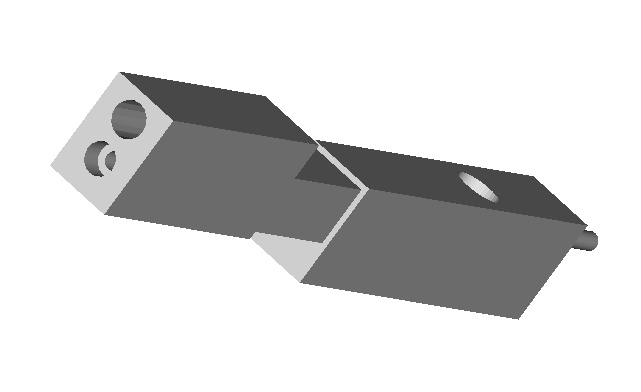 You can see that the heated barrel is drilled not only to allow passage of polymer as it is heated and is pumped towards the extruder tip but also to accomodate a 300 watt cartridge heater.
Now let us insert the cartridge heater. There is a quite inexpensive anti-lock compound that will prevent the cartridge heater from freezing up in its housing after a number of heating cycles. You will have to imagine the wires for the cartridge heater extending out the back of its housing towards the rear of the extruder. These cartridge heaters use regular lines electricity.You can also quite easily acquire bimetallic thermostats which can be used to control the temperature of the system. Like the cartridge heaters, these thermostats are very old technology and are also quite inexpensive.
  From this point we can apply the front and back retainer plates.
These are held in place by screwing the extruder tip into the heated extruder barrel on the front side and screwing the thrust bearing into the pump barrel on the back side of the assembly.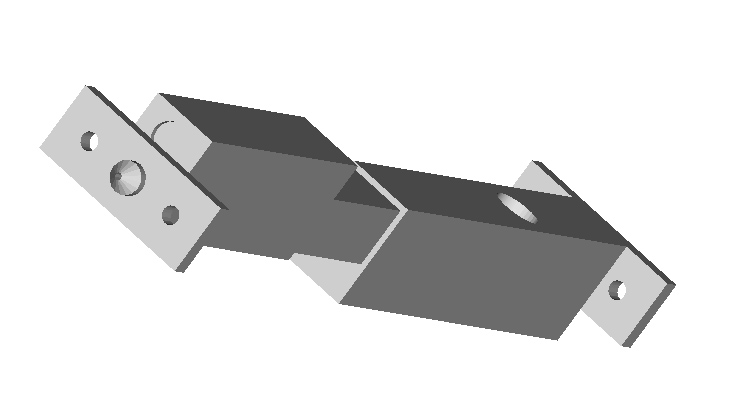
From there you secure the whole device with retaining rods made from threaded studding which are secured with lock nuts on both sides of the extruder.
This arrangement hopefully will preclude the extruder from coming apart from the internal pressure of some 40 atmospheres created by the pumping action of the polymer pump. I've calculated that this pressure will create an axial thrust of about thirty pounds.
Once that is done you simply add the feed funnel for directing polymer powder resin into the polymer pump feed chamber and you should be good to go.
I was going to use the gear motor for the Mk II, but decided that there was too much drama in accomodating such a small piece of equipment into what is a rather large (about 1 foot long and weighing 5-10 lbs) piece of equipment.  Using an electric screwdriver will, I think, make the question of securing the system to a mounting block considerably easier.
As for operating the system, I already own an infrared thermometer which will allow me to measure the surface temperature of the heated extruder barrel rather well. Initially, I plan to let the system heat up slowly whilst empty by adjusting the thermostat (which I will tap mount into the chin of the extruder barrel, not shown) until I get the temperature I want. At that point I will start the electric screwdriver and start feeding polymer into the system. The thermal capacity of the system is very much larger than the that of the polymer flow, so I doubt that the system will much notice the polymer being extruded from it energetically.
This design largely emerged as an effort to salvage some of the materials bought for the old Gingery extruder but not used. It was also designed with an eye towards being easy to break down and clean in case of jams and allows for the performance of different polymers and also different diameter extruder tips to be surveyed. The cartridge heater is also magnitudes more robust than the hair-think nichrome wire that we are currently using in the Mk II. Adrian noted that dipping his extruder head in hot water to get polymer out wouldn't be good for his device. I can demount the extruder barrel by loosening the retainer rods, slide the heater cartridge heater out, remove the retaining plate and extruder tip and immerse the extruder barrel into boiling water with no danger whatsoever. :-)
Now... objections... observations?
![]()