Monday, August 28, 2006
RepRap To Go
The Zaphod prototype has now acquired its second head, and the entire machine is now portable. At least, I can carry it out onto the deck without putting my back out.
The RepRap 3D software and ArtOfIllusion are now running nicely on the Linux laptop - should work just fine on a Windows laptop too, I just don't have one.
All this means the RepRap is now ready to go to Vienna on the 8th September for Paraflows '06 and for its TV debut on Taugshow on the 16th September. Zaphod is very excited about meeting the public and being on TV.
Vik :v)
Thursday, August 17, 2006
First part printed by Zaphod
Two announcements in one, really. The new machine has been cristened "Zaphod" on the grounds that it is going to have two heads. But with just one head installed it has printed out a linkage part, the first printed by a RepRap. Here it is just after printing, a process that took 35 minutes and used about 1.7cc of polymer:

Here it is prised off the deposition surface and next to a scale. I left sprue & cobwebbing in place for this photo, but that mostly vanishes when you wave it over a blowtorch:

Now, all those people who said it couldn't be done can start contemplating tasty recipies for their words.
Vik :v)
Here it is prised off the deposition surface and next to a scale. I left sprue & cobwebbing in place for this photo, but that mostly vanishes when you wave it over a blowtorch:
Now, all those people who said it couldn't be done can start contemplating tasty recipies for their words.
Vik :v)
Wednesday, August 16, 2006
A hole in my theory
I missed the obvious in my RepStrap...
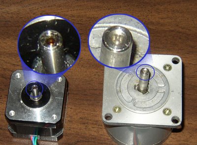
The axes wobble a bit due to the plastic sleeving used to connect the motor shaft to the studding. The sleeving slowly moves off-center from the weight of the load. Then when the motor turns it causes a wobble.
I suddenly realised the obvious. Most steppers have a little hole down the shaft. A pin inserted into the hole and then into a matching hole on the studding would keep them nicely centered and the plastic sleeving would then do a great job. The pin would be held in place by the sleeving too, so it's a very simple solution to the problem.

Tuesday, August 15, 2006
Rack those pinions...
Got it! 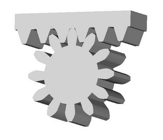
The Luleå involute gear script gears and the Kiplinger racks script match up perfectly. I ran the y-zero line for the rack through the pressure radius so that it would be easy to line up gears and racks to check to see if they mated properly.
To check you just make your rack and when doing so specify the number of teeth you want in the pinion. Also make sure that you use the same pressure radius. Once you have your rack done you then make your involute profile gear.
One thing to remember is that if you want to match up your pinion gear with your rack to always specify an even number of teeth in the rack. The reason for this is that the Involute Profile Gear script always places a gear tooth pointing straight up so you need a gap in the rack teeth to seat it without a lot of drama. Once you've done that just select your gear profile and click "object layout". Drop the gear profile in the Y-direction by a value equal to your pressure radius and you will be able to see in an instant whether or not you have a match. It's a dead easy way to avoid design errors.
Half a dozen more scripts like this and AoI will be a proper engineering design CAD system. :-D
I was thinking about short-term, unintended consequences of RepRap this morning. If I remember correctly one of the big problems in engineering education is getting students hands-on time with machine tools so that they can get some experience about where CAD design leaves off and real mechanisms begin. Machine shops and their staff are extremely expensive in my experience and students rarely if ever rate shop time just to tinker with designs.
It seems to me that RepRap would make it possible to put a good prototyping system in any mechanical engineering student's dorm room. The notion of what a RepRap would do towards improving a mechanical engineering student's experience with actually designing mechanisms completely boggles my mind. A student working with a RepRap could easily leave university with more hands-on design experience than a graduate engineer currently picks up in several years in the field. That's noteworthy to say the least. It would make engineering education both better and cheaper. In commonwealth countries it would mean lots more better trained engineers, never mind in the UK.
That alone, Adrian, should get you at least a knighthood and if the world were a fair place a peerage. A professorship would also seem the least that could happen. I don't know if you've ever entertained those sorts of ambitions, but there it is.
You can get both the Rack and the matching Involute Profile Gear scripts at...
http://www.sanma12.com/reprap/software/AoI Scripts/
For you AoI newbies you put these in the "Tools" folder that you find in your "Scripts" folder for Art of Illusion (AoI).
You have to restart AoI before you will be able to see them in the "Scripts" entry in the "Tools" pull-down menu.
One thing Professor Adamson at Lunds Technical University taught me was that the fastest way to see if you had bugs in computer code was to test extreme examples. Here is one.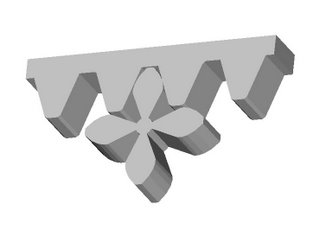
Looks good. :-)
One thing I have noticed is that you need to keep an eye on the AoI extruder facility when you are extruding your rack. Occasionally it will put a little two dimensional web across part of the bottom of one of your rack teeth. You can generally see it as a wrinkle in the sides of the rack when you view it in AoI. I don't know why that is, but you should look out for it. I've found that increasing or decreasing the number of teeth in the rack makes it go away... for now...
Please remember that while the Involute Profile Gear script has been knocked around a bit, the Rack script is a very early beta release. Please let me know if you find any problems with it. Thanks! :-)

The Luleå involute gear script gears and the Kiplinger racks script match up perfectly. I ran the y-zero line for the rack through the pressure radius so that it would be easy to line up gears and racks to check to see if they mated properly.
To check you just make your rack and when doing so specify the number of teeth you want in the pinion. Also make sure that you use the same pressure radius. Once you have your rack done you then make your involute profile gear.
One thing to remember is that if you want to match up your pinion gear with your rack to always specify an even number of teeth in the rack. The reason for this is that the Involute Profile Gear script always places a gear tooth pointing straight up so you need a gap in the rack teeth to seat it without a lot of drama. Once you've done that just select your gear profile and click "object layout". Drop the gear profile in the Y-direction by a value equal to your pressure radius and you will be able to see in an instant whether or not you have a match. It's a dead easy way to avoid design errors.
Half a dozen more scripts like this and AoI will be a proper engineering design CAD system. :-D
I was thinking about short-term, unintended consequences of RepRap this morning. If I remember correctly one of the big problems in engineering education is getting students hands-on time with machine tools so that they can get some experience about where CAD design leaves off and real mechanisms begin. Machine shops and their staff are extremely expensive in my experience and students rarely if ever rate shop time just to tinker with designs.
It seems to me that RepRap would make it possible to put a good prototyping system in any mechanical engineering student's dorm room. The notion of what a RepRap would do towards improving a mechanical engineering student's experience with actually designing mechanisms completely boggles my mind. A student working with a RepRap could easily leave university with more hands-on design experience than a graduate engineer currently picks up in several years in the field. That's noteworthy to say the least. It would make engineering education both better and cheaper. In commonwealth countries it would mean lots more better trained engineers, never mind in the UK.
That alone, Adrian, should get you at least a knighthood and if the world were a fair place a peerage. A professorship would also seem the least that could happen. I don't know if you've ever entertained those sorts of ambitions, but there it is.
You can get both the Rack and the matching Involute Profile Gear scripts at...
http://www.sanma12.com/reprap/software/AoI Scripts/
For you AoI newbies you put these in the "Tools" folder that you find in your "Scripts" folder for Art of Illusion (AoI).
You have to restart AoI before you will be able to see them in the "Scripts" entry in the "Tools" pull-down menu.
One thing Professor Adamson at Lunds Technical University taught me was that the fastest way to see if you had bugs in computer code was to test extreme examples. Here is one.

Looks good. :-)
One thing I have noticed is that you need to keep an eye on the AoI extruder facility when you are extruding your rack. Occasionally it will put a little two dimensional web across part of the bottom of one of your rack teeth. You can generally see it as a wrinkle in the sides of the rack when you view it in AoI. I don't know why that is, but you should look out for it. I've found that increasing or decreasing the number of teeth in the rack makes it go away... for now...
Please remember that while the Involute Profile Gear script has been knocked around a bit, the Rack script is a very early beta release. Please let me know if you find any problems with it. Thanks! :-)
Monday, August 14, 2006
Under pressure
On Saturday, July 08, 2006 I blogged a start at a design for a peristaltic pump for driving pastes and the like through RepRap deposition heads. One of the adjuncts that this needs is a pressure sensor so the microcontroller can tell when to turn the pump on and off.
Here's a thing:
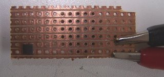
The little grey square on the left is a quantum tunnelling compound pill, which you can find out more about here, and buy here (product id: N18BU). But all you really need to know is that its resistance drops when you squash it, and it costs £0.50.
If you place it on some stripboard as above, then put a soft silicone tube over it, then clamp them together you get this arrangement:
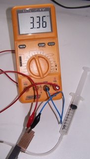
The tube is blocked at the left, and the hypo will (in a moment) apply pressure. As you screw the clamp jaws together the resistance goes down - in the picture it's 3.36K.
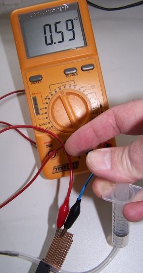
Now depress the plunger:

The resistance drops gratifyingly smoothly to 590 ohms. Better yet, if you pull on the plunger to create a partial vacuum, the resistance rises above 3.36 K...
It should be very simple to design a little RP screw clamp to hold a small piece of stripboard, the QTC pill, and the soft tube. It might be better to use gold flash on the stripboard contacts, to avoid oxide contamination problems over time. The device could be placed in any pressure line, or attached to a blind tube as above.
Here's a thing:

The little grey square on the left is a quantum tunnelling compound pill, which you can find out more about here, and buy here (product id: N18BU). But all you really need to know is that its resistance drops when you squash it, and it costs £0.50.
If you place it on some stripboard as above, then put a soft silicone tube over it, then clamp them together you get this arrangement:

The tube is blocked at the left, and the hypo will (in a moment) apply pressure. As you screw the clamp jaws together the resistance goes down - in the picture it's 3.36K.
Now depress the plunger:
The resistance drops gratifyingly smoothly to 590 ohms. Better yet, if you pull on the plunger to create a partial vacuum, the resistance rises above 3.36 K...
It should be very simple to design a little RP screw clamp to hold a small piece of stripboard, the QTC pill, and the soft tube. It might be better to use gold flash on the stripboard contacts, to avoid oxide contamination problems over time. The device could be placed in any pressure line, or attached to a blind tube as above.
Rethinking everything...
Posts by Sebastien and Simon got me to thinking this morning about RepRap. Sebastian's post led me to recalculate a number I did way back last November and Simon's post made me mad, something I've always found to be a good spur to creative thought. Thanks go to you both. :-)
Sebastien's post was to Vik asking him what the extrusion rate of Da Witch was. Vik guessed at 1 cc/min. I responded doing an envelope calculation which indicated that Vik's calculation was just short of a magnitude off. From the message...
Figuring a 0.8 mm extrusion thread and running at the 4 mm/sec that Mk II was designed for you're getting about 2 mm^2/sec. or 7.24 cc/hr which gives you a modest, but not unreasonable 5.2 kg/month on a constant duty cycle.
Way back last November I made a calculation of extrusion rates when Adrian first published the Mk II extruder. The number I came up with then was 2.83 cc/hr or roughly 2 kg of polymer/month if operated full-time.
It was always obvious to me that 2 kg/month of polymer extrusion for 24x7 operation was just not practical. This morning I realised, however, that my calculation did not allow for the non-Newtonian swelling of the extruded polymer thread. I was figuring that the thread that came out of the Mk II was the same diameter as the orifice. WRONG! Vik has seen that a 0.5 mm orifice yields a 0.8 mm polymer thread.
Now extruding 5.2 kg/month of polymer is a whole different ball game.
That got me to thinking about Godzilla, which I have targeted 20-40 mm/sec extrusion rates. I've learned a lot designing and building Godzilla and at this point I am sure that I can get it to work, probably at about 20 mm/sec. That would extrude something like 26 kg of polymer a month.
There are some practical problems with Godzilla, though.
It's big. It's got a 700x700x350 mm work volume. It's footprint is about 1.5 square meters. It's also loud. Frankenmotors don't scream, but they are full-throated. Two of them running at once will make about as much noise as an electric blender. If you were married you couldn't keep Godzilla in the house with your wife unless she was as committed to 3D prototyping as you are. That's probably an unreasonable filter for guys wanting to marry to put on potential mates. It just wouldn't work. I'm crazy, live by myself, divorced and have a bit of hearing loss from my misspent youth, so Godzilla doesn't bother me. Most people would be bothered, though. As a practical matter Godzilla would have to live in somebody's workshop and it wouldn't be a machine that you'd want to leave running overnight or over the weekend. As a practical matter you're not going to be able to run it for more than about 8 hours/day.
That means that you're only going be extruding about 8.7 kg of CAPA a month with it, that's only 2/3rd's more than Vik's machine. Now it can make lots bigger things than Da Witch, but realistically, how often are you likely to be making huge things with your RepRap?
That's a bitter pill for me, but there it is all the same.
Now let's get to Simon's message that made me mad, but in a creative way. He indicated that servos aren't on for now, that it has to be steppers. Well, I've probably got more hours working with turning brushed DC motors into servos than anybody on the team and I couldn't disagree more. Now Frankenmotors need some work and a lot of thinking to be used properly. The little yellow plastic G4 gearmotor servo is a very different story. Here's why.
You can get steppers surplus for about US$5-10/unit. The moment that RepRap takes off, however, surplus steppers are going to evaporate and people will be paying list price for them, which is about US$50-75/unit. That means that if you are shooting for a US$400 RepRap the steppers are going to cost you 40-60% of that. Parts for stepper boards are also going to cost you another US$15 or so in parts when all is said and done. That means that you're talking about 50-70% of your RepRap budget going for just motors and control boards before you even try to build the positioning stages and extruder. That's just not on.
Now I can buy a yellow plastic G4 gear motor retail for between US$5-6/unit.
http://www.pololu.com/products/solbot/0181/
Add a shaft encoder to that and you've got US$10. That's 20% of the real cost of a stepper. As well, the much lower power draw means that the chips you have to buy to drive the motor are cheaper. Finally, most of the mass and cost of the G4 and it's siblings is in the plastic gear box. The motor itself can be had for maybe US$1.50/unit retail. The rest you can reprap if you want.
What all this means is that the cost of your motors and control boards for gearmotor servos for a Vik-sized RepRap is going to be maybe US$60, and a bit less if you make your own gear boxes.
Now let's do a thought experiment. Let's take Reiyuki's pretty conventional (in CNC terms) gantry design for a wooden RepStrap.
He thoughtfully provides us with a materials quantity survey.
24x48" of 1/8"
48" of 1x2
16" of 1x3
74" of 1x4
78" of 1x6
Doing the numbers you get roughly 17250 cm^3 of materials volume. In wood that gives you about 10 kg of material. In CAPA it would be more like 17.5 kg.
If you redesigned Reiyuki's system for CAPA from the get go you can bring that number down to about 3.5 kg. Pushing it harder you could probably shave another kg off of that, but why bother?
What it all means is that a Reiyuki RepStrap could make a full polymer copy of itself in 20 days.
What it also means is that you could make one for under US$200, everything included... if you went the G4 gearmotor servo route. Double that if you use steppers.
A Reiyuki RepStrap has a 300x600 mm footprint. That's not much worse than most ink-jet printers. Put hoods over those G4's and you will have something that is probably considerably quieter than your ink-jet. Run the whole shebang on 12v power and you're not going to worry about letting it run nights and weekends. Reiyuki's design, when you look at it, isn't all that different than Vik's, which we know works. It uses threaded rods and we don't stress them to the extent Godzilla does. Same general configuration. It scales, too.
If we take my own proclivity for dynamic extruder heads we can probably either reduce the footprint or increase the capacity for a set footprint. I tend to think that G4's running positioning platforms using RepRapped rack and pinions (yes, I've just about got the script running) could make a lighter system still with fewer hard metal parts to buy.
You're can naturally make spare parts for a design like this when you aren't actually using the system for something else. There will be a natural tendency to make spares and keep maybe two systems going for reliability. Two systems not all that much bigger than Vik's have a hell of a lot of extrusion capacity, viz, about 11 kg/month.
The present paradigm has your PC running the RepRap. Put a bigger PIC18F chip in the controller and your PC could handle several RepRaps.
Having spares around is going to give you a natural tendency to help other people get theirs going, too.
Sebastien's post was to Vik asking him what the extrusion rate of Da Witch was. Vik guessed at 1 cc/min. I responded doing an envelope calculation which indicated that Vik's calculation was just short of a magnitude off. From the message...
Figuring a 0.8 mm extrusion thread and running at the 4 mm/sec that Mk II was designed for you're getting about 2 mm^2/sec. or 7.24 cc/hr which gives you a modest, but not unreasonable 5.2 kg/month on a constant duty cycle.
Way back last November I made a calculation of extrusion rates when Adrian first published the Mk II extruder. The number I came up with then was 2.83 cc/hr or roughly 2 kg of polymer/month if operated full-time.
It was always obvious to me that 2 kg/month of polymer extrusion for 24x7 operation was just not practical. This morning I realised, however, that my calculation did not allow for the non-Newtonian swelling of the extruded polymer thread. I was figuring that the thread that came out of the Mk II was the same diameter as the orifice. WRONG! Vik has seen that a 0.5 mm orifice yields a 0.8 mm polymer thread.
Now extruding 5.2 kg/month of polymer is a whole different ball game.
That got me to thinking about Godzilla, which I have targeted 20-40 mm/sec extrusion rates. I've learned a lot designing and building Godzilla and at this point I am sure that I can get it to work, probably at about 20 mm/sec. That would extrude something like 26 kg of polymer a month.
There are some practical problems with Godzilla, though.
It's big. It's got a 700x700x350 mm work volume. It's footprint is about 1.5 square meters. It's also loud. Frankenmotors don't scream, but they are full-throated. Two of them running at once will make about as much noise as an electric blender. If you were married you couldn't keep Godzilla in the house with your wife unless she was as committed to 3D prototyping as you are. That's probably an unreasonable filter for guys wanting to marry to put on potential mates. It just wouldn't work. I'm crazy, live by myself, divorced and have a bit of hearing loss from my misspent youth, so Godzilla doesn't bother me. Most people would be bothered, though. As a practical matter Godzilla would have to live in somebody's workshop and it wouldn't be a machine that you'd want to leave running overnight or over the weekend. As a practical matter you're not going to be able to run it for more than about 8 hours/day.
That means that you're only going be extruding about 8.7 kg of CAPA a month with it, that's only 2/3rd's more than Vik's machine. Now it can make lots bigger things than Da Witch, but realistically, how often are you likely to be making huge things with your RepRap?
That's a bitter pill for me, but there it is all the same.
Now let's get to Simon's message that made me mad, but in a creative way. He indicated that servos aren't on for now, that it has to be steppers. Well, I've probably got more hours working with turning brushed DC motors into servos than anybody on the team and I couldn't disagree more. Now Frankenmotors need some work and a lot of thinking to be used properly. The little yellow plastic G4 gearmotor servo is a very different story. Here's why.
You can get steppers surplus for about US$5-10/unit. The moment that RepRap takes off, however, surplus steppers are going to evaporate and people will be paying list price for them, which is about US$50-75/unit. That means that if you are shooting for a US$400 RepRap the steppers are going to cost you 40-60% of that. Parts for stepper boards are also going to cost you another US$15 or so in parts when all is said and done. That means that you're talking about 50-70% of your RepRap budget going for just motors and control boards before you even try to build the positioning stages and extruder. That's just not on.
Now I can buy a yellow plastic G4 gear motor retail for between US$5-6/unit.
http://www.pololu.com/products/solbot/0181/
Add a shaft encoder to that and you've got US$10. That's 20% of the real cost of a stepper. As well, the much lower power draw means that the chips you have to buy to drive the motor are cheaper. Finally, most of the mass and cost of the G4 and it's siblings is in the plastic gear box. The motor itself can be had for maybe US$1.50/unit retail. The rest you can reprap if you want.
What all this means is that the cost of your motors and control boards for gearmotor servos for a Vik-sized RepRap is going to be maybe US$60, and a bit less if you make your own gear boxes.
Now let's do a thought experiment. Let's take Reiyuki's pretty conventional (in CNC terms) gantry design for a wooden RepStrap.

He thoughtfully provides us with a materials quantity survey.
24x48" of 1/8"
48" of 1x2
16" of 1x3
74" of 1x4
78" of 1x6
Doing the numbers you get roughly 17250 cm^3 of materials volume. In wood that gives you about 10 kg of material. In CAPA it would be more like 17.5 kg.
If you redesigned Reiyuki's system for CAPA from the get go you can bring that number down to about 3.5 kg. Pushing it harder you could probably shave another kg off of that, but why bother?
What it all means is that a Reiyuki RepStrap could make a full polymer copy of itself in 20 days.
What it also means is that you could make one for under US$200, everything included... if you went the G4 gearmotor servo route. Double that if you use steppers.
A Reiyuki RepStrap has a 300x600 mm footprint. That's not much worse than most ink-jet printers. Put hoods over those G4's and you will have something that is probably considerably quieter than your ink-jet. Run the whole shebang on 12v power and you're not going to worry about letting it run nights and weekends. Reiyuki's design, when you look at it, isn't all that different than Vik's, which we know works. It uses threaded rods and we don't stress them to the extent Godzilla does. Same general configuration. It scales, too.
If we take my own proclivity for dynamic extruder heads we can probably either reduce the footprint or increase the capacity for a set footprint. I tend to think that G4's running positioning platforms using RepRapped rack and pinions (yes, I've just about got the script running) could make a lighter system still with fewer hard metal parts to buy.
You're can naturally make spare parts for a design like this when you aren't actually using the system for something else. There will be a natural tendency to make spares and keep maybe two systems going for reliability. Two systems not all that much bigger than Vik's have a hell of a lot of extrusion capacity, viz, about 11 kg/month.
The present paradigm has your PC running the RepRap. Put a bigger PIC18F chip in the controller and your PC could handle several RepRaps.
Having spares around is going to give you a natural tendency to help other people get theirs going, too.
Sunday, August 13, 2006
Hatching a thicker plot
Forrest has been working on bitmap-based infill algorithms for depositing the build material in layers; these have the advantage of being very robust, but they are a bit memory hungry.
Meanwhile, I have been improving the infill routines for the Java CSG representation.
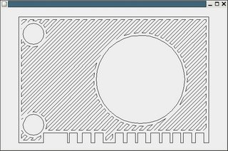
Above is a test piece. The outer rectangle and the circles are the delineation of the shape that the machine lays down first. It then follows the hatch lines to infill between those boundaries. The hatch needs to be offset by the stream width inside the boundary (and the outer boundary needs to be offset inwards by half that width from the true boundary). The hatch follows a series of "pen down" movements that are all connected to minimise the amount of "pen up" movement.
Well. I say minimise. It's actually a fast heuristic. A true minimisation would be a travelling-salesman solution, which would probably be a bit slower...
Rack and Pinion...
I converted Kiplinger's maths to code and tested them. His pinion gear routine seems to be nothing more than an involute profile gear like we already have. Mind, the Swedish approach seems more robust than Kiplinger's. His routine for generating rack gear strips is trivial and appears to be very robust. I've got that going in a VB.NET test programme and will sort out the problems, such as they are, in it before shifting it over to a Java script that will work in Art of Illusion. Most of the "problems" are making sure that the routine generates a proper loop of line segments and resolving a terms difference between the input data for the Swedish involute profile gear programme and the rack programme. I don't think that is going to be any big deal.
Here is a sample rack I generated with the VB.NET code prototype routine.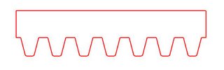
It is a 14.5 degree pitch angle rack.
Just for variety here is a 20 degree angle rack. Pitch angles of 14.5 and 20 degrees are pretty much the industry standard for this kind of gear technology.
Here is a sample rack I generated with the VB.NET code prototype routine.

It is a 14.5 degree pitch angle rack.

Just for variety here is a 20 degree angle rack. Pitch angles of 14.5 and 20 degrees are pretty much the industry standard for this kind of gear technology.
Second prototype gets some guts
I've got the electronics mounted up and the motors installed. This is much more of a working environment than a prototyping environment, so all the baords have been hived off into a little plastic box. It has a lid, and maybe one day that'll fit on. Meanwhiles, I fear the spaghetti will proliferate a bit. Thought you might want to see this morning's progress:

Yes, I know we planned to mount the little boards on the parts that they control. However, I need equipment that will survive the airline baggage handling system so something a little more robust is needed.
There have been questions about how the Polymorph and No. 8 wire are used to hold on the Mk 2a head, so here's a detail view with the background shaded out to clarify things. The long machine screws have a nut on them underneath the Polymorph, which is in turn cored with single strands of No. 8 galvanised fencing wire:

A wire end can be seen sticking out lower right. The saddles provide a handy anchor for hose clamps, and are contoured with a lip to help keep the clamp in place. The black heater power cable snakes through the view.
Vik :v)
Yes, I know we planned to mount the little boards on the parts that they control. However, I need equipment that will survive the airline baggage handling system so something a little more robust is needed.
There have been questions about how the Polymorph and No. 8 wire are used to hold on the Mk 2a head, so here's a detail view with the background shaded out to clarify things. The long machine screws have a nut on them underneath the Polymorph, which is in turn cored with single strands of No. 8 galvanised fencing wire:
A wire end can be seen sticking out lower right. The saddles provide a handy anchor for hose clamps, and are contoured with a lip to help keep the clamp in place. The black heater power cable snakes through the view.
Vik :v)
Saturday, August 12, 2006
Diagonal Infilling...
After Adrian's warning about the dangers of overlaying the same pattern slice after slice, I went back and developed an alternating diagonal infill routine. One of the issues that I had to confront was what to do when the perimeter routine couldn't deal with a feature of a slice that was narrower than a perimeter extrusion track. That required a little routine that determined which parts of the slice were outside of the perimeter after the perimeter had been developed. 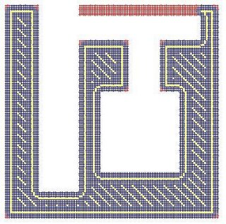
You can see the results here. That red bit at the top is a feature that is narrower than a single trace of the Mk II. You can also see some red bits on the corners that represent parts of the slice that are too fine for the Mk II extrusion to reach.
Yesterday, Adrian suggested that I should be a bit more forthcoming with my developments both in documenting them and making them available while they are in the development phase. His point is very well taken in that I consider what I do almost perpetually "in development".
On the other hand, I am well aware of the fact that I am a very untidy person and am hesitant to let that untidiness flood into places like RepRap's subversion system. I'm going to try something that might be the best of both worlds. To that end I've opened up a directory on my own server...
http://www.sanma12.com/reprap
...as a repository for my extensive, messy, non-standard "developments", such as they are. For those of you working in a Wintel, Visual Studio.NET development environment my current code can be acquired at...
http://www.sanma12.com/reprap/software/VB.NET PC-Side Control System/Grid 09 upload 120806.zip
For the more orthodox RepRappers who are using Linux and Java, still feel free to grab my code and give it a look if you suspect that there may be something useful to what you want to do. VB.NET isn't very hard to read if you know where to look in the half-dozen files that a Visual Studio project generates.
In this case all of the actual BASIC code can be found in Form1.vb. Just open that file up in some sort of text editor and search for #End Region. The actual code follows that statement which is at the end of a bunch of statements that tell Visual Studio how to set up the form with buttons, labels and the like. The code proceeds from #End Region to the end of the file in plain ASCII text.
Going a bit further, the routine has three procedures that are taken in the following order...
Private Sub Button1_Click(ByVal sender As System.Object, ByVal e As System.EventArgs) Handles Button1.Click
When I actually get something that is more or less complete, I'm talking about subsystems, you can be sure that it will be documented and placed in the Wiki and/or the subversion files.

You can see the results here. That red bit at the top is a feature that is narrower than a single trace of the Mk II. You can also see some red bits on the corners that represent parts of the slice that are too fine for the Mk II extrusion to reach.
Yesterday, Adrian suggested that I should be a bit more forthcoming with my developments both in documenting them and making them available while they are in the development phase. His point is very well taken in that I consider what I do almost perpetually "in development".
On the other hand, I am well aware of the fact that I am a very untidy person and am hesitant to let that untidiness flood into places like RepRap's subversion system. I'm going to try something that might be the best of both worlds. To that end I've opened up a directory on my own server...
http://www.sanma12.com/reprap
...as a repository for my extensive, messy, non-standard "developments", such as they are. For those of you working in a Wintel, Visual Studio.NET development environment my current code can be acquired at...
http://www.sanma12.com/reprap/software/VB.NET PC-Side Control System/Grid 09 upload 120806.zip
For the more orthodox RepRappers who are using Linux and Java, still feel free to grab my code and give it a look if you suspect that there may be something useful to what you want to do. VB.NET isn't very hard to read if you know where to look in the half-dozen files that a Visual Studio project generates.
In this case all of the actual BASIC code can be found in Form1.vb. Just open that file up in some sort of text editor and search for #End Region. The actual code follows that statement which is at the end of a bunch of statements that tell Visual Studio how to set up the form with buttons, labels and the like. The code proceeds from #End Region to the end of the file in plain ASCII text.
Going a bit further, the routine has three procedures that are taken in the following order...
Private Sub Button1_Click(ByVal sender As System.Object, ByVal e As System.EventArgs) Handles Button1.Click
- reads in the STL file
- generates the slice
- sets up the grid and determines what part of the grid lies within the grid
- develops the perimeter extrusion track
- determines what part of the slice lies within the perimeter
- does the infill
When I actually get something that is more or less complete, I'm talking about subsystems, you can be sure that it will be documented and placed in the Wiki and/or the subversion files.
Next gen RepRap in progress
Da Witch has now given way to a new model, currently without designation, that has been constructed in a frame of thick-walled copper piping. I've used a mixture of copper saddles and hose clamps, but it could be done with hose clamps throughout:

The frame is bedded in with Polymorph to two bits of 3x2 , currently held to the bench with G-clamps. The head and X-axis are held into the copper frame by hand-moulded Polymorph and hose clamps. Ordinary cable clips hold the wiring into place.
This is the model likely to be exhibited at Paraflows '06 in Vienna, travel arrangements permitting.
Vik :v)
Friday, August 11, 2006
Infilling...
After thinking about all of the drama involved in a cross-hatching scheme I got to wondering what would happen if I just used the perimeter tracing routine over and over to do the infill. Here is what happened. 
I first tried the gears since I thought that they would be the most challenging.
Remarkably, there was very little in the way of voids left in the extrusions.
The first serious problem I had with voids occurred with the non-convex example that I did for Adrian.
This last slice from the bead support structure I just threw in because I liked the pattern it made. I was an architect for a long time, so sue me. :-P
I am wondering now if it would be possible to fill the more egregious voids by simply making passes over them with the Mk II with the extrusion rate throttled down for the translation speed and sort of squeeze polymer into the voids using the already extruded walls as molds.
I first tried the gears since I thought that they would be the most challenging.

Remarkably, there was very little in the way of voids left in the extrusions.

The first serious problem I had with voids occurred with the non-convex example that I did for Adrian.
This last slice from the bead support structure I just threw in because I liked the pattern it made. I was an architect for a long time, so sue me. :-P
I am wondering now if it would be possible to fill the more egregious voids by simply making passes over them with the Mk II with the extrusion rate throttled down for the translation speed and sort of squeeze polymer into the voids using the already extruded walls as molds.
Wednesday, August 09, 2006
Serious tests...
I went ahead and ramped up the analysis speed of the routine another two magnitudes so that I could try to slice and trace perimeters for some serious STL files in reasonable, not geological, time frames. I used the involute profile gear script for AoI to generate a 13-toothed gear with a pitch diameter of about 20 mm. The STL file contained 30,486 triangles. I set the grid at 0.1 mm and let it rip. The perimeter is about 0.4 mm across. I probably should make it a bit bigger, but you get the idea.
Not bad, huh? :-D It looks a little rough till you realise that this is really quite a small gear, only about 48 mm in diameter... just under two inches.
Next I'm going to do top down slicing and calculate the support structures. Using Adrian's approach it should be a snap. :-)
Then I'll be revisiting the infill question. :-s
Tuesday, August 08, 2006
Grids rock!
Finally got my head around how to solve the border problem. Grids rock!
 Not only do they track the perimeters properly, but they also show you the path for the centre of the MK II extruder head, won't let you overlap and shows you the corners and blind pockets that the Mk II isn't going to be able to get into.
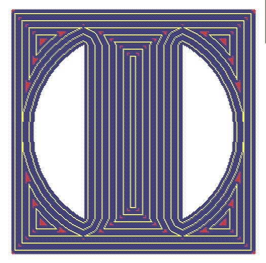
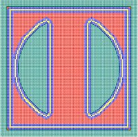
In this pic the background is cyan, the perimeter is blue with the extruder path done in yellow. The red bits comprise the rest of the slice of the object. I haven't done an infill routine yet.
You can see how the Mk II can't quite get into the corners of the slice.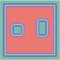
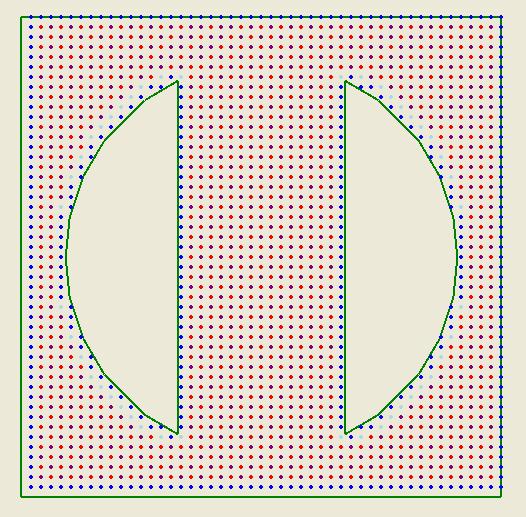
Here is a slice of a rectangular box with two holes in it. Looks pretty good for a start. :-D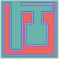
Here is a really, really non-convex slice especially for Adrian. :-D
After looking at Adrian's non-convex polygon, which took a long time to do, I felt sufficiently confident in the approach to migrate some more of the coding from the old slice and dice programme that I wrote a few days ago into the grid. This improved the execution speed of the routine by about 1.5-2 magnitudes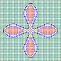 . There are a few other tricks that I can use if need be to kick that speed up another 1.5-2 magnitudes. I'm not going to do it unless execution speed really gets to be an issue again. Because PC's always get lots faster if you wait about 18 months I tend to value code reliability and simplicity a lot more than I do efficiency.
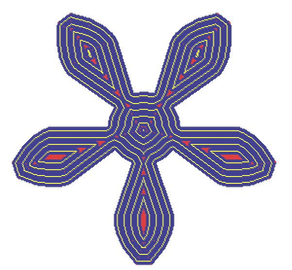
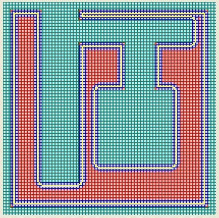
Finally, here is a perimeter trace for a 4-toothed involute profile gear. For this kind of shape I am beginning to wonder if our one-size-fits-all notion of using diagonal, 90 degree offset infills is really a good idea for all the sorts of things we'd like to make. If you look at the inner spot of infil required for this gear it would seem that a quick doubling of the perimeter depth would be more appropriate, ditto with the infills in the teeth. This requires some more thought, I suspect.
I am particularly excited about the prospect for leveraging this method with some heuristics that give the user some useful graphics feedback about whether the RepRap machine can actually make the part the user is designing. I suspect this is going to be a very big issue for the sorts of RepRap users who are using their machines to create new devices rather than simply making salad bowls and napkin rings.
 Not only do they track the perimeters properly, but they also show you the path for the centre of the MK II extruder head, won't let you overlap and shows you the corners and blind pockets that the Mk II isn't going to be able to get into.
In this pic the background is cyan, the perimeter is blue with the extruder path done in yellow. The red bits comprise the rest of the slice of the object. I haven't done an infill routine yet.
You can see how the Mk II can't quite get into the corners of the slice.

Here is a slice of a rectangular box with two holes in it. Looks pretty good for a start. :-D
Here is a really, really non-convex slice especially for Adrian. :-D
After looking at Adrian's non-convex polygon, which took a long time to do, I felt sufficiently confident in the approach to migrate some more of the coding from the old slice and dice programme that I wrote a few days ago into the grid. This improved the execution speed of the routine by about 1.5-2 magnitudes
 . There are a few other tricks that I can use if need be to kick that speed up another 1.5-2 magnitudes. I'm not going to do it unless execution speed really gets to be an issue again. Because PC's always get lots faster if you wait about 18 months I tend to value code reliability and simplicity a lot more than I do efficiency.
 Finally, here is a perimeter trace for a 4-toothed involute profile gear. For this kind of shape I am beginning to wonder if our one-size-fits-all notion of using diagonal, 90 degree offset infills is really a good idea for all the sorts of things we'd like to make. If you look at the inner spot of infil required for this gear it would seem that a quick doubling of the perimeter depth would be more appropriate, ditto with the infills in the teeth. This requires some more thought, I suspect.
I am particularly excited about the prospect for leveraging this method with some heuristics that give the user some useful graphics feedback about whether the RepRap machine can actually make the part the user is designing. I suspect this is going to be a very big issue for the sorts of RepRap users who are using their machines to create new devices rather than simply making salad bowls and napkin rings.
Sunday, August 06, 2006
First try at grids...
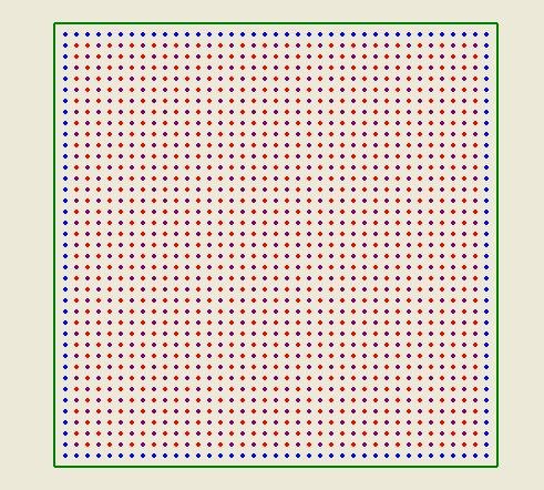
Laying out the grids and finding out what part of the grid lay inside the STL files was no problem. I used a quasi-boolean approach with a little smoothing added to find the perimeter boundaries.
The light blue grid nodes represent diagonals from the points that test outside of the STL boundaries.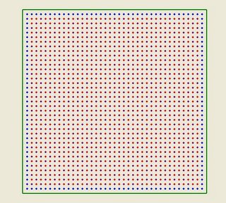
 Here you can see the infil diagonals set in purple.
The light blue grid nodes represent diagonals from the points that test outside of the STL boundaries.
 Here you can see the infil diagonals set in purple.
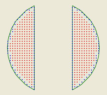
Saturday, August 05, 2006
Time to try another approach...
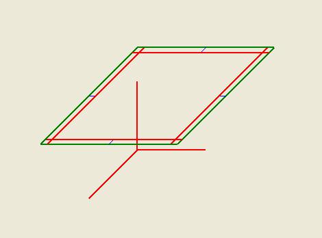
That little glitch in the slicing and dicing software turned out to be a very big glitch, a conceptual glitch, in fact. Turns out that the insetting method that I was using to create the perimeter path for the Mk II has a real hassle. You can see it here.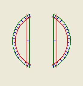
The green line segments represent a slice across the bead and the red lines represents the attempt to inset them. It turns out that if you have a straight line meeting a curved line at an acute angle you can get some real problems with overlaps where the overlap can mean that several curved line segments can protrude beyone your straight line. That makes my little clip or extend routine more than a bit problematic.
Right off hand I can't see a way to fix that which doesn't involve me checking every inset line to see if it intersects with another inset line. That's just about an n^2 calculation problem which is a terrible thing to have in your code.
I'm half-tempted to go on and steal Adrian's grid approach and salvage the rest of my routines to work with that. I'm going to think about this for a few more hours before I do that, though. Maybe I'll think of something sneaky. :-)
Quick and dirty support structures...
I was gritting my teeth and preparing to write a lot of coding to build support structures around objects to be fabricated. That seemed like it could be as big a job as actually writing the extrusion control programme and I wasn't looking forward to doing it.
Then I think it was yvan roy who said something about using Pov-Ray to do the job which made me remember something that I thought about a long time ago, that is, that it would be neat to leverage the boolean solids operator in AoI to do the slicing and dicing. That would have entailed a major rewrite of AoI, though, a prospect that nobody on the team was excited about doing, much less maintaining after the fact.
Yvan's comment twigged me to thinking about that again and I realised that we ought to be designing the support structure for objects in AoI at the same time we design the object. That doesn't require any rewriting at all.
Suppose, for example, you designed a bead like this and it needed to be oriented like this when you were reprapping it.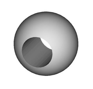
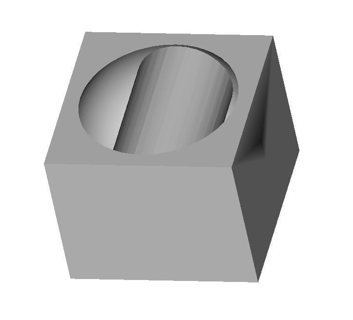
All you'd have to do is envelop it and the cylindrical void in the bead with a rectangular solid like this...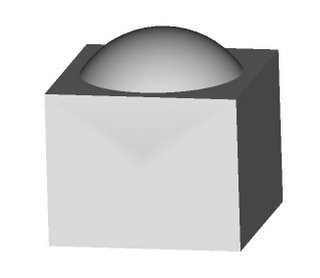
...and then do a boolean operation on the two to remove the bits of the rectangular solid that the bead occupied like this.
This is a snap to do in AoI.
Then you use your handy dandy slicing and dicing software to slice and compute extrusion paths for the support structure...
...and then the bead...
{I still have a little code glitch with how the inner perimeters are drawn but you can see how it works anyway.}
...then tag the slice files for the support structure as requiring the polyfil, or whatever, extrusion head and the bead as requiring the CAPA extrusion head.
Merging the two files into one which has the support part and the object part for each layer of the extrusion project should be child's play.
Mind, this may have been something that has already been thought of and Adrian may have had something of the sort in mind all along, but, if it hasn't and/or if he didn't there it is. :-)
Then I think it was yvan roy who said something about using Pov-Ray to do the job which made me remember something that I thought about a long time ago, that is, that it would be neat to leverage the boolean solids operator in AoI to do the slicing and dicing. That would have entailed a major rewrite of AoI, though, a prospect that nobody on the team was excited about doing, much less maintaining after the fact.
Yvan's comment twigged me to thinking about that again and I realised that we ought to be designing the support structure for objects in AoI at the same time we design the object. That doesn't require any rewriting at all.
Suppose, for example, you designed a bead like this and it needed to be oriented like this when you were reprapping it.

All you'd have to do is envelop it and the cylindrical void in the bead with a rectangular solid like this...

...and then do a boolean operation on the two to remove the bits of the rectangular solid that the bead occupied like this.
This is a snap to do in AoI.
Then you use your handy dandy slicing and dicing software to slice and compute extrusion paths for the support structure...

...and then the bead...

{I still have a little code glitch with how the inner perimeters are drawn but you can see how it works anyway.}
...then tag the slice files for the support structure as requiring the polyfil, or whatever, extrusion head and the bead as requiring the CAPA extrusion head.
Merging the two files into one which has the support part and the object part for each layer of the extrusion project should be child's play.
Mind, this may have been something that has already been thought of and Adrian may have had something of the sort in mind all along, but, if it hasn't and/or if he didn't there it is. :-)
A good start at slicing and dicing...
The VB.NET programme now does slicing, dicing and creating paths for the Mk II extruder to follow. 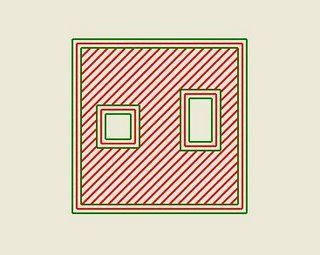
Here is a slice from a rectangle with two rectangular holes in it. The red lines represent the paths for the Mk II extruder.
Similarly, here is a slice across a sphere for comparison. The green lines represent the outer boundaries of the perimeter extrusions. I've got to plowshare the infill paths to minimise the time the positioning stages require to do the extrusion.
The code at this point isn't very sophisticated, but it is a starting point and appears to be robust for the purposes at hand.
Now I have to decide whether I want to do something else for a change or tackle the problem of doing support structures. I'm thinking that there is a sneaky way of skinning that particular cat. :-)

Here is a slice from a rectangle with two rectangular holes in it. The red lines represent the paths for the Mk II extruder.

Similarly, here is a slice across a sphere for comparison. The green lines represent the outer boundaries of the perimeter extrusions. I've got to plowshare the infill paths to minimise the time the positioning stages require to do the extrusion.
The code at this point isn't very sophisticated, but it is a starting point and appears to be robust for the purposes at hand.
Now I have to decide whether I want to do something else for a change or tackle the problem of doing support structures. I'm thinking that there is a sneaky way of skinning that particular cat. :-)
Thursday, August 03, 2006
More slicing and dicing...
I got the perimeter line segments into inner and outer loops and consolidated line segment fragments lying on the same line (an artifact of using STL files). Now I've begun creating the inset paths for the Mk II to follow to make the outer perimeter of the object. 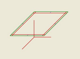
You can see the overlap of the inset perimeter lines. I have to clip off those excesses.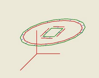
Similarly, here you can see that the perimeter of an inner loop, in this case a square hole in an elliptical cylinder don't quite reach and will have to be extended.
After that trimming and adding I will have to create yet another inset set of perimeter loops which will reflect the inside boundary of the perimeter extrusion put down by the Mk II. That will server as an outer boundary perimeter for doing the cross-hatch paths for the Mk II to fill the layer once the outer perimeter extrusion has been put down. There will be a little more trickiness with that as well, I expect.
I'm getting there, though. :-)
You can see the overlap of the inset perimeter lines. I have to clip off those excesses.

Similarly, here you can see that the perimeter of an inner loop, in this case a square hole in an elliptical cylinder don't quite reach and will have to be extended.
After that trimming and adding I will have to create yet another inset set of perimeter loops which will reflect the inside boundary of the perimeter extrusion put down by the Mk II. That will server as an outer boundary perimeter for doing the cross-hatch paths for the Mk II to fill the layer once the outer perimeter extrusion has been put down. There will be a little more trickiness with that as well, I expect.
I'm getting there, though. :-)
![]()