Friday, September 29, 2006
RepRap Interview on Austrian TV
 Last weekend's "Taugshow #6" featuring an interview section on the RepRap by yours truly aired on Austria's Okto TV channel and is now online here:
http://www.monochrom.at/taugshow/taugshow6.htm
It's 300-odd MiB. For those skipping through it, I'm the longhair in the orange T-shirt in the latter half, as seen here on the right.
Vik :v)
Saturday, September 23, 2006
First Working Part Printed & Fitted
This part was printed at 10:10pm Austrian time on the 13th September 2006, and was fitted the following morning (I got carried away celebrating the moment, OK?). For the record, it involved 15390.4 mm of travel, 11240.9 mm of extruding, has a volume of 4.777 cm^3 and took 6690.9s to print (about 1 hr 50 mins). Oh yeah, it works.

Vik :v)
Vik :v)
Thursday, September 14, 2006
Quick update from Vienna
Things are going astoundingly well here, except for networking issues which prevent me from uploading pictures. But it is probably worth mentioning that last night I completed the first full part for the RepRap and I'll be fitting it this morning. It's the largest thing printes so far containing - if I recall correctly - 4.4cc of polymer and taking 1hr 10 mins to print out. The improved print speed is due to the lack of excessive head cooling during the workpiece cooling cycles. If you look at the Youtube clip (see comments to previous entry) you'll see that I've chopped up a clear plastic bottle to create a windshield.
Rolling 3mm polymorph by hand has been part of my life all week, and it's good to hear the news from the builder's blog that it might be possible to get pre-made fillament.
For those in Vienna, check the Metalab.at site for details on tonight's "How to build your RepRap" session and come along to this morning's brunch if you can. Tomorrow, we shoot the Taugshow interview, which given Johannes Grenzfurthner's reputation (see his Wikipedia entry) should be very interesting - for me at least!
Vik :v)
Wednesday, September 13, 2006
RepRap Makes a Name for Itself
After a late night session and early morning session supporting Metalab and apparently a few of the local breweries, the RepRap has finally made a name for itself:

It looks like we'll have to take greater care not to route the nozzle over gaps in the artifacts so as to avoid all the "hair". But at least we know that the mechanism is actually capable of producing reasonable volumes of output without breaking down, and I can confirm that I can hand-roll 3mm fillament faster than the RepRap can use it!
More from the opening of the Metalab exhibition here:
http://esel.at/gallery2/v/dokumentation/paraflows/paraflows_opening/paraflows__opening_metalab
Vik :v)
Sunday, September 10, 2006
RepRap on display in Vienna
Greetings from Vienna, or as they say in these parts "Servus!"
Zaphod has survived the trip, and despite having flown Auckland-Sydney-Bangkok-Dubai-Vienna sustained remarkably little dammage (a few disconnected wires, a detatched circuitboard and a broken fan housing). The Vik however was totally knackered, and took about 3 hours to reassemble the pieces.
Aha! Found the apostrophe on this QWERTZ keyboard (or kezboard as I keep doing).
We've had a wonderful reception by the Paraflows '06 organisers, and the Metalab - particularly Philipp who is kindly putting me up for the duration. I am sorry I was not awake enough to go out on the evening festivities with Angela and her loyal crew. Hopefully we will have other opportunities.
The press have been throughly primed, and even Google News in Austria has picked up a link :) Here
But now, time for breakfast in Vienna.
Vik :v)
Monday, September 04, 2006
Use of Castable Bearings in RepRap
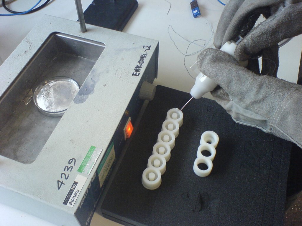
Apologies for the delay in posting this....
A few weeks ago I attempted to produce some bearings using Field's metal and RP moulds. The aim was to prove that it was possible for a RepRap machine to produce its own bearings, as Field's metal melts at approximately 70 degrees celcius......
I tried 2 methods
1. Casting the metal in a mould with the 8mm steel bar in situ, using silicone grease as a spacer.
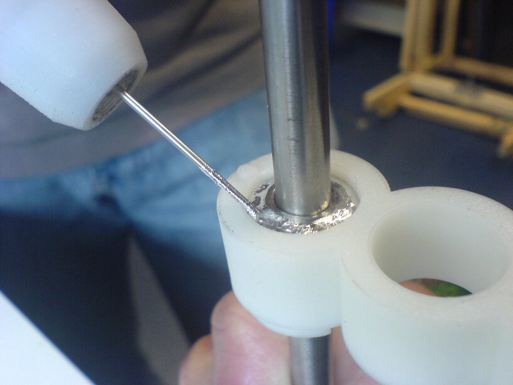
2. Casting the metal in a mould with a plug that could be hammered through once the metal had solidified.

Method 1 failed as a bearing (but would be good as a locating/fixing mechanism - ie calibrate
machine, then set all joints in metal)
Method 2 produced some nice bearings..... (Only tested by hand so far)
The Moulds
Method 1 - 3 hole mould and cap used to locate the rod and seal the base.
Method 2 - 6 hole mould with varying plug diameters, the support material needs to be left on to hold the plug in place.

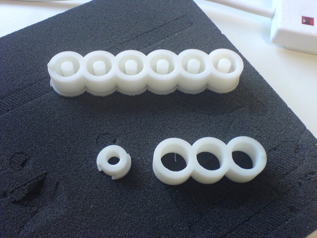
Moulds 1 & 2 and concentricity cap, and the finished bearings (before knocking through plugs)
The best results were achieved with a centre plug diameter of 8.2mm (to fit an 8mm bar)
Will be performing some basic tests on them this week
Fulll report available if anyone is interested
Sunday, September 03, 2006
The mystery deepens
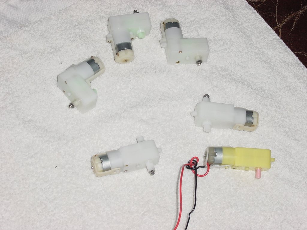
I got the Solarbotics gearmotors in today. I laid the little yellow gearmotor that Adrian sent me months ago alongside the GM3 that I bought and I can say this.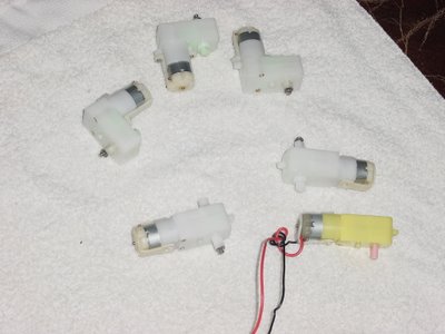
If these weren't made for the same manufacturer they were made by the same factory, somewhere in Guandong province in the Peoples' Republic, I suspect.
The mounting holes on the case are identical as is everything else right down to the distortions to the outside of the case that come as a result of reinforcing struts inside cooling in the injection molding dies.
The gear ratios are different, I suspect, because of a change in the nature of the windings. The motor cases are identical.
There is no need to change the Mk II STL file for the mounting block for the gearmotor.
I bought the GM3 with its 38 rpm peak rotational rate largely because I didn't need all that much rotational speed on the Mk II polymer pump motor and I wanted to put a shaft encoder on it. Dan at Solarbotics said that he would be more than happy to plunk the GM9 gears into the GM3 gearbox if we needed that higher rotational speed.
The mounting holes on the GM8's with its different gear box and motor orientation are in a different place. This shouldn't be a problem, though.
Ah ha! There is a difference. While to drive shaft is a double flat on the Solarbotics just like the one Adrian has it is enough bigger that it is too robust to fit in the motor coupling that he made for the Mk II.
Saturday, September 02, 2006
Common components for KiCad
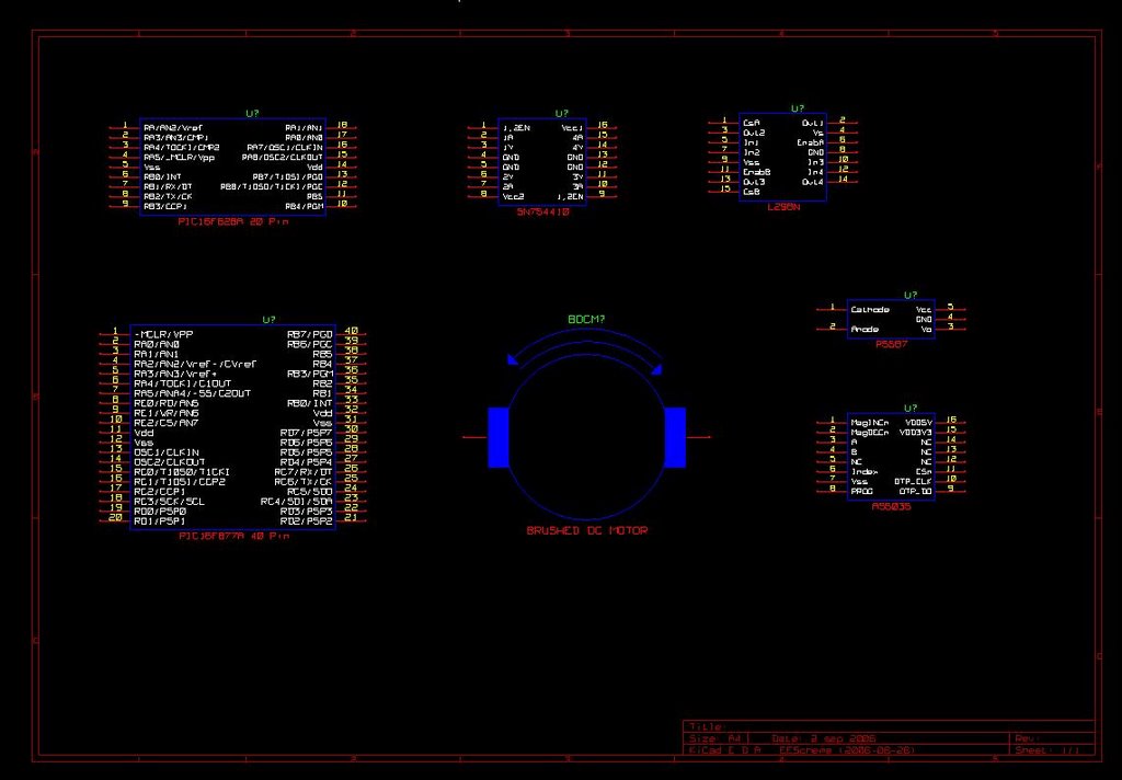
I went ahead and created components for the usual sorts of things that we use around here.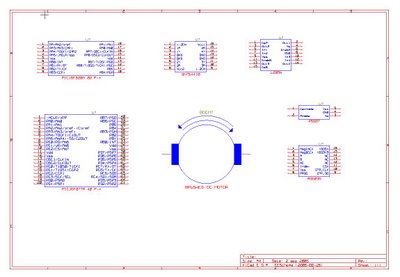
Most of the components we ordinarily use are already in KiCad's libraries. These include the 16F628A and the 16F877A. I just hate the serendipitous manner in which they distribute pins on their IC's though, so I went ahead and did them like they are on the data sheets.
We're going to have newbies trying to build these boards and it's confusing enough trying to see what connects to what without some boffin playing 52 card pickup with the pin numbers on the poor okies.
Anyhow, if anybody needs the new library, let me know and I'll email it to you. My server is still down. :-(
BTW, I've already seen the typo with the 16F628A. I called it a 20 pin chip when it is actually an 18. I fixed it but don't want to generate a new sample sheet this evening.
Friday, September 01, 2006
Biting the KiCad bullet...
I finally decided to take a little time off and learn KiCad so that I can document some of the boards that I'm building. I went back and read over Adrian's 5 March entry in the Developer's blog. From that and looking at the schematics I have the suspicion that I might be the only one to be actively using it to document things.
Here is the paper trail on it...
Simon (11 January):
Vik made a great discovery of a package called Kicad.
It's a complete integrated schematics -> PCB system and it looks pretty good. It's fully GPLd and multi-platform. I was just playing with it before and it's pretty simple to use. I built a schematic and took it right through to the PCB stage quite quickly. It can also produce SVG of schematics, and mirrored postscript of copper tracks for quick and dirty UV optical etching.
Adrian (5 March)
I'm about to blog my experiences with 1) kicad and 2) laserprinting
and Adrian blogged that same day that...
...took me about an hour once I got up to speed. Kicad's automatic PCB layout tools are almost useless, but its systems to assist manual layout are very good - they are clear, and don't allow you to make mistakes. Here's the PCB for the above circuit:
Vik (27 June)
We're looking at kicad, gschem and eagle.
From what I've seen so far KiCad looks to be open source or while Eagle is a commercial package that has a limited use free edition. I'm not fond of "limited" free editions, so I'm going with KiCad.
So far, so good. The first thing that becomes apparent is that some of the chips that we're fond of aren't in their library. They have an editing feature in KiCad, but as Adrian suggested in his blog entry, it's about as easy to just cut and paste in the library files, since they are in ASCII. One thing Adrian didn't mention probably because it didn't happen to him, if you edit the library files using a text editor be aware that the code in KiCad that reads those files isn't idiotproof, so if you make a typo while editing and then try to start up the schematic programme, it will explode. Don't let that alarm you, just go back and check your library editing. You probably just have a typo.
One thing to keep an eye on. There are a number of library files in the library folder that aren't activated in the eschema (schematic... this is French software, but don't let that put you off) Before you go to a lot of trouble to put in a new chip schematic check those libraries. I was about to bite the bullet and put in the 16F877A when I found a very useful copy of it in an inactive library. I just cut and pasted that into the Microchip library and I was good to go.
Anyhow, I couldn't find our H-bridge chips so I'm doing schematics for them as practice. Here is the 754410...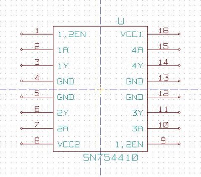
I am also going to do the L298N H-bridge, the AS5035 shaft encoder chip and that Hamamatsu limits detector chip that I can't remember the number for right off hand. If anybody is going to use those give me a yell and I'll send you the altered libraries. I'll put them in my resources folder as soon as my server is operational again, which will be next weekend, I think.
Here is the paper trail on it...
Simon (11 January):
Vik made a great discovery of a package called Kicad.
It's a complete integrated schematics -> PCB system and it looks pretty good. It's fully GPLd and multi-platform. I was just playing with it before and it's pretty simple to use. I built a schematic and took it right through to the PCB stage quite quickly. It can also produce SVG of schematics, and mirrored postscript of copper tracks for quick and dirty UV optical etching.
Adrian (5 March)
I'm about to blog my experiences with 1) kicad and 2) laserprinting
and Adrian blogged that same day that...
...took me about an hour once I got up to speed. Kicad's automatic PCB layout tools are almost useless, but its systems to assist manual layout are very good - they are clear, and don't allow you to make mistakes. Here's the PCB for the above circuit:
Vik (27 June)
We're looking at kicad, gschem and eagle.
From what I've seen so far KiCad looks to be open source or while Eagle is a commercial package that has a limited use free edition. I'm not fond of "limited" free editions, so I'm going with KiCad.
So far, so good. The first thing that becomes apparent is that some of the chips that we're fond of aren't in their library. They have an editing feature in KiCad, but as Adrian suggested in his blog entry, it's about as easy to just cut and paste in the library files, since they are in ASCII. One thing Adrian didn't mention probably because it didn't happen to him, if you edit the library files using a text editor be aware that the code in KiCad that reads those files isn't idiotproof, so if you make a typo while editing and then try to start up the schematic programme, it will explode. Don't let that alarm you, just go back and check your library editing. You probably just have a typo.
One thing to keep an eye on. There are a number of library files in the library folder that aren't activated in the eschema (schematic... this is French software, but don't let that put you off) Before you go to a lot of trouble to put in a new chip schematic check those libraries. I was about to bite the bullet and put in the 16F877A when I found a very useful copy of it in an inactive library. I just cut and pasted that into the Microchip library and I was good to go.
Anyhow, I couldn't find our H-bridge chips so I'm doing schematics for them as practice. Here is the 754410...

I am also going to do the L298N H-bridge, the AS5035 shaft encoder chip and that Hamamatsu limits detector chip that I can't remember the number for right off hand. If anybody is going to use those give me a yell and I'll send you the altered libraries. I'll put them in my resources folder as soon as my server is operational again, which will be next weekend, I think.
![]()