Sunday, February 22, 2009
Pull Yourself Together, Bot!
Warning: this is gonna be a long post. Grab a hot cocoa and settle into a comfy chair.
Fresh off a month long RepRap-building workshop binge, I have many ideas to try out and many places to apply polish on the RepRap project. Doing nothing but assembling RepRap designs for the past month has taught me quite a few things, both good and bad. There are many things that we're doing really well on, and a few areas where we can improve on. In particular, the XY assembly is really nice. Skeinforge and the RepRap host software rock, as well as some of the next generation stuff (pinch wheel extruder, gen 3 electronics, etc.) The stuff that isn't quite as easy is the frame assembly, the Z axis, and the bearings (or lack thereof) on the Y axis (on the darwin design).
Anyway, this post is about some experimental work I did this past week that was inspired by those experiences. In particular, it focuses in on two questions that are very closely related:
1. How can we simplify the corner brackets to be easier to assemble as well as easier to print.
2. Is is possible for the machine to be partially self-assembling?
Question #1 was inspired because I've been having a hell of a time trying to print the corner brackets, as well as assembly troubles. Aside from warping issues, the design itself calls for lots and lots of trapped nuts to be placed inside the part. This in turn requires that you have a finely tuned machine that works exactly how it should to produce them... which is not something most people have. If you're like me, your RepRap machine is sort of hacked together and must be lovingly coaxed into printing what you want. Not only that, but even with commercially produced 3D parts, getting the nuts into the holes can best be described as a dark art.
So, follow me along my train of thought as I present a way of making this part simpler. The corner bracket has 2 main jobs: create the basic structure for a cubic frame, and to be the place for various 'accessories' to mount on, such as the XY axis assembly, z motor, etc. In doing so, the corner block has routing holes for rods going in the X, Y, and Z direction. Basically, its just a part thats full of right-angles. Looking over the rest of the RepRap design, theres a part that I really like: the diagonal tie bracket. It's simple, no-fuss, and easy to print. Not only that, but this guy is basically just a printable right-angle!

I did a bit of napkin designing on the flight over to Madrid and realized that if you took two of these things, they could substitute for a single corner block by taking two and rotating one 90 degrees. If you had 8 of these parts, then you could make an XY frame. If you had two of those, you'd have the top and bottom XY frame. Of course they will also easily work as the diagonal ties they were designed to be. The only modification you'd need to make is to add an extra hole on the end. Then when they form an x, you'd have three of the four holes you'd get with a single block. This part is pictured on the right.
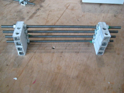
Anyway, so say you get 16 of these parts: how do you turn them into the top and bottom XY frames? Good question. The XY frame is interesting because its basically just rods with corner blocks a certain distance apart. All we need to do is take our corner ties, space them a certain distance apart, and then bingo... we'll have an XY frame. The required parts to form an XY frame is pictured to the right. Astute readers will notice a flaw in this plan though: since the two ties for each corner pivot around the Z-axis it means that the whole assembly is a bit wishy-washy. Even with every single corner tie spaced exactly perfectly, you could easily get a parallelogram instead of a square. How do we make the frame square? Simple! Make a diagonal rod with two ties spaced exactly the right distance apart and attach it to the Z rods so that they form a perfect, right-angle triangle!
Now, I know what you're thinking.... holy crap that sounds awful. I'll have to measure each of these things very precisely and make sure they're exactly correct otherwise my machine will be slightly off and my children will hate me, drop out of school, and then the economy will tank. Well don't worry my friend, because I've managed to stumble onto the answer, and it involves question #2: Is is possible for the machine to be partially self-assembling?
So, is it possible? I say yes! Yes, it is! The answer is that we make the machine do the measuring and we coax it and guide it along. If you have a sharp eye, you'll notice that the XY frame parts above are constructed from THREADED rod instead of SMOOTH rod. The rod used is the same rod that we use for our Z axis, and I specifically got the crappiest rod I could find in order to really test to see if this is viable.

Okay, so how exactly do I propose we have the machine self-assemble? Easy! We use a stepper motor, some threaded rod, a python script, and a few other parts to turn the RepRap technology into a precision kebab-building machine! Here's how it works: I created a reference design in QCad. (which I totally forgot to check into subversion, sorry!) From this design, I created a python script that creates GCode instructions for building the various kebabs. The GCode consists mainly of two parts: instructions that prompt the user to do things: thread a nut on the rod, slide on kebab parts (diagonal ties, washers, etc) and actual instructions that cause the rod to rotate a nut to exactly the right position. The end result is pretty slick: it generates a wizard that serves as both a guide and a self assembly program. You the user just sit back and do what your robot overlord prompts you to do. A screenshot is shown on the right here.
Of course, all this was just a random idea in my head until a couple days ago when I sat down and actually tried to do it. Let me just say this: it works way better than I thought it would! Even with the various inaccuracies I introduced by making my own parts by hand, all the parts still managed to fit together without any jamming, bending, or forcing of parts. my reprap machine is down due to cannibalism for the workshops)
It was really cool to sit down and have a conversation with someone while occasionally following the prompts from the laptop, and ending up with 4 kebabs that were all perfectly spaced and ready for use. It was even cooler to put the diagonal ties created by the same method onto the frame and watch it be pushed into a perfect square. It was even cooler to install the Z kebabs, the second XY frame, and finally the vertical diagonals and have them all settle nicely into place without fuss. The only measuring I did was in cutting the rods and accuracy wasn't all that important there.
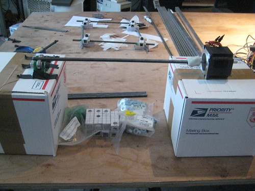
A picture of the rig I used to build the kebabs is on the right. Its just a stepper motor, a motor coupling for the rod, an M8 rod, and an idler to make the process easier. The stepper is hooked up to a standard driver which is hooked up to a RepRap Motherboard which is hooked up to my computer which is running the GCode on ReplicatorG. The only custom part here is the idler to make the threading process easier. Everything else is stuff you'll need to build the machine anyway!!!! I had to hack my own coupling together, but the standard RepRap Z motor coupling would work without any sort of modification. With a bit of clever coding and a re-application of the tools that we already have, it becomes simple to do this.
Now, what are the implications of this? Obviously its a very simple technique that you the builder needs to take part in, so we won't have self-copying robots that self-assemble running amok. However, there are some really cool things that are going on here:
1. the design is parameterized! the python script takes all sorts of parameters that control the gcode that is output. things like X, Y, and Z dimensions so you could build a big RepRap machine, or a small reprap machine! it also takes things like rod size, washer size, and nut size so you can easily convert the script to imperial, or use M5 hardware. it also has some cool options for the build such as leaving out washers, or using thread locking compound for those adventurous souls who never wish to take their machine apart.
2. the instructions are the design! the first 20 lines of the gcode are instructions such as the number of nuts you'll need, the number and lengths of the various rods you'll need, as well as various bits of information such as volume diagonal lengths, etc. not only that, but as its an interactive process, it makes assembly a snap: you simply follow the step-by-step instructions and the various parts go together in front of your eyes. no more digging through complicated build instructions. just connect the dots!
3. we can do lots of other cool things: dynamically generate a DXF template for the bed? sure! dynamically generate STL files for the diagonal ties? sounds awesome! one day you may be able to use the same script to generate a miniature reprap for building ant-sized things or to generate a reprap for building buildings! these things still need to be implemented, but the framework is there.
Now, what about the drawbacks? There are definitely a few issues, and it certainly isn't the technique to end all techniques. Here are a few off the top of my head.
Problem: The starting position of the nut is crucial. I eyeballed it and got good results, but it certainly is a source of error. It should be at the exact same position at the beginning of every move. My solution: create a 'nut starter' device that acts like an endstop, and then have the stepper 'home' until it hits it thus ensuring every nut starts at exactly the right place.
Problem: Once a nut is positioned, minor rotations can move it out of position. (ie: 1/2 turn on M8 rod is 0.625mm) This can happen accidentally, or to the previous nuts when you rotate the next ones on. My solution: use a bit of modeling clay (or blue-tack) to hold the nut into place until you can tighten it down. It seems to work pretty well.
Problem: If your rod is dirty, or the thread damaged then the nut can slip from your fingers as the rod is rotating, causing you to lose your position. This really sucks, because GCode doesn't have any real support for moving back or re-executing a command. It's not totally fatal however, because most assemblies have two nuts: a front one and a back one. If one of them slips, you can use the other as a datum. Its best if you don't let the nut slip. My solution: put a bit of oil on the rod before threading nuts, as well as running a wire brush just ahead of the nut on the first pass for a rod. Long-term, it would be nice to make a little carriage that holds the nut in place and allows you to do other things while its automatically placing it.
Anyway, it's probably about time to wrap this post up. This was a fun experiment and I'm very happy with how it turned out. It's still very much under development, and I'll be hacking on this quite a bit in the coming weeks. I think its a very promising path for development of the reprap project. If you'd like to play along, or just check out the work that I'm doing, I store everything in my reprap subversion folder. This particular project is codenamed 'Pythagoras' because its based on triangles and also because its generated using a Python script. The project specific scripts and drawings are located in hoeken/pythagoras. You can also check out my flickr set with a few photos. I was too excited to take more, but if this turns out to be a really good path, you can be sure I'll fully document the process.
Thanks for reading, and I look forward to your comments.
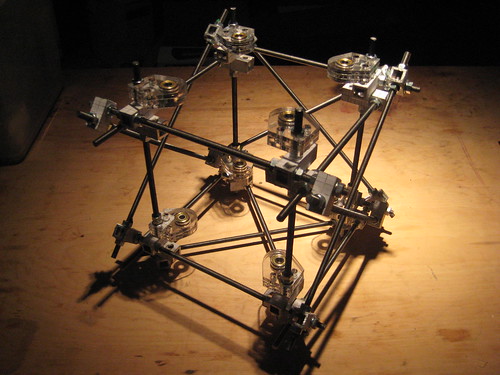
PS. the very first picture is the prototype frame i assembled. its exactly 330mm x 330mm x 330mm outside dimensions. i plan on building a much bigger one in the future as well.
Racks and pinions

Wherein your narrator takes a explores ways of upping the milled or printed content of future Reprap machines... do you want to hear more?
Saturday, February 21, 2009
Tip: Easy Way to Thread Y Belt
My friend and collaborator Sunil at Interactivos 09 came up with a clever way of threading the Y belt through the Y belt idler assembly. Check it out:
Easy Way To Thread Belt from Zach 'Iowa' Hoeken on Vimeo.
Easy Way To Thread Belt from Zach 'Iowa' Hoeken on Vimeo.
Friday, February 20, 2009
OLPC Viewfinder

The OLPC XO Laptop for kids has a camera built in to the front of it. Great for video chat, but not so good for when the kids want to point the camera at something that is away from them. There is a commercial viewfinder but now it has been reprapped:

Here it is fitted:
If anyone wants to modify it, the Thingiverse URL is: http://www.thingiverse.com/thing:330
Hopefully this is the first of a large number of objects that can be made by schools using a RepRap to further their children's education and enjoyment.
Vik :v)
Labels: olpc, viewfinder
Stepper pinch-wheel extruder building
RepRap stepper extruder working from Adrian Bowyer on Vimeo.
Here's the prototype stepper pinch-wheel extruder building the coat hook. As Nophead has always rightly maintained, good control of the polymer flow gives the best quality results. This one came out as good as the ones he makes on Hydraraptor. And the slow-running-stepper lights are pretty...
It may also be possible to use a pinch-wheel extruder to drive a syringe - simply put a plastic-coated metal shaft through it, and use that to push/pull the plunger. But because of the large diameter of any useful syringe, the stepper may have to be running so slowly that the output would be a bit jerky. Microstepping may solve that, of course.
Wednesday, February 18, 2009
IR Ranging

Tuesday, February 17, 2009
Sanguino Software v1.4 Release
Marius Kintel has been doing some excellent hacking and updating of the Sanguino code. This guys is a rockstar, and I just have to give him props for his help. Sometimes I have a bad tendency of starting projects and not tending to them as I should (sorry!!!!) This release is pretty much 100% him, oh wait... it is all him. He fixed some bugs with the serial stuff, and just generally made it awesome.
Hip hip hooray!
You can download the new software from Google Code.
EDIT: test *before* releasing... ;) removed stale files. all 2 of you, please re-download.
Hip hip hooray!
You can download the new software from Google Code.
EDIT: test *before* releasing... ;) removed stale files. all 2 of you, please re-download.
Back From Madrid
 Whew! I'm back from Interactivos '09 in Madrid where I was leading the project to build a reprap machine. It was a really fun, really intense 2 week project where we built an entire, functioning RepRap machine from scratch (well, sort of... we used PCBs and printed parts)
I'd like to give a big thanks to the whole Medialab Prado crew. They are really some awesome people over there doing some really rad things. They made me not ever want to leave Madrid. The city and people and culture they have there are really something to be proud of. It sort of makes my hometown of NYC seem a bit backwards. ;)
Here's a quick brain dump:
* tornillas = bolts
* tuercas = nuts
* canas = hangover ;)
* tapas = awesome :)
RepRap machines *can* be built from parts made on a Z Corp machine, but its tough and you have to be careful. We broke some parts and had to hack together some replacements.
It was really cool to use the machine to print out parts to fix itself and thus improve build quality. We broke the Z motor coupling and cobbled a fix together with hose clamps and heat shrink tubing. The Z axis had some major wobble. One of the first parts we printed was a replacement Z motor coupling from ABS. we put it on and the wobble improved dramatically. Yay for self-replication!
I learned how to do 3d modeling (gasp! yes, i dont know how to... this project is so fricking huge!!!) I learned about Sketchup, Blender, and how to make the two play nicely (blog post coming soon)
Edit: I also learned a really cool technique for doing embossed lettering on printed parts. Blog post coming soon.
Anyway, big shouts to my collaborators: Catarina, Ricardo, Guillermo, Kirsty, Erica, Christine, Juan, and everyone else who stopped by to pitch in that I have forgotten.
Cheers,
Zach
RP Pinch-wheel Extruder II

It does turn out to be possible to knurl a stepper shaft (see blog immediately below). As you can see, I had to take the rotor out to do it. Minus point: needs fancy kit (knurling head, lathe). Plus point: only took a few seconds, so someone could do hundreds in an afternoon. The new extruder now has one fewer parts...
Tip: clean it really really thoroughly before you re-assemble the stepper...
Here's a vid of it working with ABS:
RepRap direct-drive stepper extruder from Adrian Bowyer on Vimeo.
See how fast it runs! Note how it stops and starts on a dime! Of course, the faster we extrude the faster we can build things, and - what's more - the less significant dwells and melt ooze become.
If I may be permitted to quote Zach: Yay!
Sunday, February 15, 2009
RP Pinch-wheel Extruder

Inspired by Zach's lasercut pinch-wheel extruder and a comment from Ian ("I bet you could drive that direct with a stepper motor.") I decided to do just that and to create an RP design that RepRap could make.
Unfortunately, my RepRap was in bits having a couple of new toothed-belt cogs fitted, so I had to make this one in the Strat.
So. Here is a prototype. It works...

What's more, it only has two RP parts: the clamp that holds the heated barrel and attaches the device to the RepRap machine, and the pinch device itself. Here the whole thing is being driven by Zach's new stepper driver.

Here it is in bits. As you can see I put a brass collar on the stepper shaft. The collar has a knurled section to drive the plastic filament. (Improvement: I suspect it'll be possible to knurl the stepper motor's shaft itself and to get rid of that brass bit.) The filament is squashed against a ball race. (Improvement: use a smaller ball race and cut the size down.) Neither the ball race nor the collar need any sort of groove to guide the plastic - that is achieved by the hole down the block through which it runs.
I adjust the gap by sliding the whole motor in slots, rather than the more obvious method of having a slot for the ball race. This allows the latter to be very firmly mounted, and means that there are four sliding screws achieving the adjustment, which again makes things very sturdy when it's all tightened up. To get the gap, I just put a 2.5mm drill down it, push the motor against that, and tighten the screws. That compresses the 3mm filament into the knurl-ridges by 0.5 mm, which seems fine for ABS.
I'm driving it by a modified version of the GCode firmware running on a Sanguino. I need to get the hang of the timer interrupts as I don't yet have the resolution to make fine speed adjustments. That is one point: the stepper is running very slowly - about 4 steps per second. The elasticity in the system seems to smooth out the flow, though - you can see a very slight jerkiness as it comes out of the nozzle, but I don't think that will cause too much trouble.
Finally, I tried a new way of mounting the PTFE in the clamp:
 I put the PTFE in a Black and Decker and used a triangle file to run grooves in the top of it. (The little blob of Blu Tack is to prevent contamination.) I made a hole with three support webs in into which it just fits.
 Then I set it up like this, put more Blu Tack round underneath to seal it, and poured PU resin into the gap alongside the support webs. It set, and made a very solid join. I suspect that any thermoset like Araldite or JB Weld would work just as well as PU.
This was the prototype (for example it uses a very non-standard ball race that I just happened to have in a drawer). I'll do a proper design and stick it in the repository ASAP.
Labels: direct drive, extruder, pinch-wheel, stepper motor
Wednesday, February 11, 2009
First thrust plate for a printable stepper motor milled
A quick test of the printable stepper thrust plate from Forrest Higgs on Vimeo.
In which your narrator turns plans into product... do you want to hear more?
Labels: "Clanking Replicator", HDPE, milled, pneumatic stepper motor, reprap, Tommelise
Tuesday, February 03, 2009
RepRap in Madrid

RepRap (or a subset thereof: Zach and Adrian) has come to the Medialab-Prado in Madrid. Zach is running a build-a-RepRap workshop over the space of a couple of weeks, and Adrian is getting in the way, and giving a talk this evening.

One experiment we did was enabled by Adrian's bringing 3mm PLA with him (the in-flight baggage checkers didn't like it, but let it on...). So here is Zach's pinch-wheel extruder running PLA for the first time. This was important to try, as we knew it worked with ABS, but PLA is much harder (that is, more difficult to pinch). It runs just fine, though interestingly the mix that occured with the molten ABS already in there when we were purging it seemed very stiff.
And finally, nothing to do with RepRap, but some extreme gardeners extreme gardening just down the street...

Labels: talks, visits, workshops
![]()