Thursday, November 30, 2006
Universal PCB test
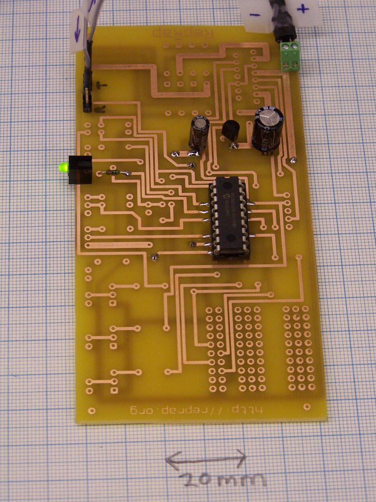
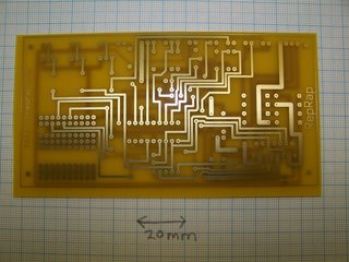
Here is the first test of the universal PCB:
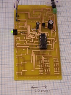
As you can see, it is not fully populated. We are trying to design RepRap so that not only can you test parts when they're finished, but so you can also test them as they're being built too.
Here I have just added the smoothing caps, the 5V reg, the PIC chip holder and the what-the-hell's-going-on? LED.
Pouring 12V into it made the LED light up, as you can see.
Better was that, when I programmed the PIC with Simon's stepper firmware then put the board in the token ring I could make the LED flash by running the RepRap Java software and asking it to move the X axis. The LEDs are supposed to flash when the motors turn, so all seems well. Now for the stepper-driver H-bridge chip...
Incidentally, the busy area bottom right is a breadboard area in which users can build their own circuitry (Vik's idea).
Wednesday, November 29, 2006
Milling about.
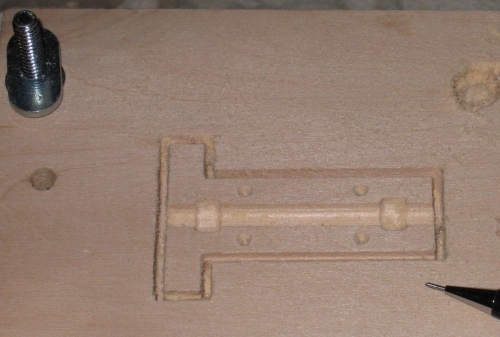 I hope this part doesn't look too unfamiliar. It's part of the extruder head, and here I've milling it out of wood using a CNC-converted Taig mill (aka my lazyman's off-the-shelf repstrap).
I'll write up more of it once I'm further along, but for highlights, I opened the .stl file in meshcam, a windows-based CAM program, and generated the g-code (the toolpaths). (Meshcam works ok under wine on linux, if you open the meshcam program using its entry in k-medu->wine->meshcam. (K-menu is the little menu in the corner of the screen.)) Meshcam doesn't work when you open it with wine via the terminal. It was extremely tedious figuring this out; I'm hoping I'll be able to use Neil Gershenfeld's cam.py to do the .stl-> g-code next time.
I'm using emc on a cheap used 500MHz linux box with a parallel port to
to do the CNC control. This involves opening the g-code file in emc and hitting "run". emc then parses the g-code and sends the right commands/5V pulses to the stepper controller circuits.
The stepper control circuits are just three breadboards hooked up to my computer via a parallel port cable. I'm using a variation on the L297/L298 reference circuits, basically this: http://www.pminmo.com/l297-8/l297-8.htm
A taig mill is probably overkill for this application (milling plastic and use as a repstrap). I bought mine for USD1K+ from Nick Carter, but viewers at home could do quite well with a sherline, proxxon, or unimat, I imagine. Note that these machines don't have the horsepower of a taig; they're smaller and lighter, but fine for milling plastic and aluminum. There's a long list of suitable already cnc-converted mills here:
http://www.desktopcnc.com/hard_pg.htm
and the cheap route is to get a sub-usd$500 chinese mill/drill
- Cummins 7877 Mini Mill
- Grizzly G8689 Mini Milling Machine
- Harbor Freight 44991 Central Machinery Mini Mill/Drill
- Homier 03947 Speedway Mini Mill
- Micro-Mark 82573 MicroLux Milling Machine
http://www.cnczone.com/forums/forumdisplay.php?f=164
Be warned that the build quality on the chinese mill/drills is highly variable, although reportedly is improving. If you buy one, buy it local, so that you can return it if yours happens to be broken/too much of a fixer-uper.
I'll write up a bit more once I've made more extruder parts out of UHMW plastic, and wiki-fy all this as well.
Bit of Edam
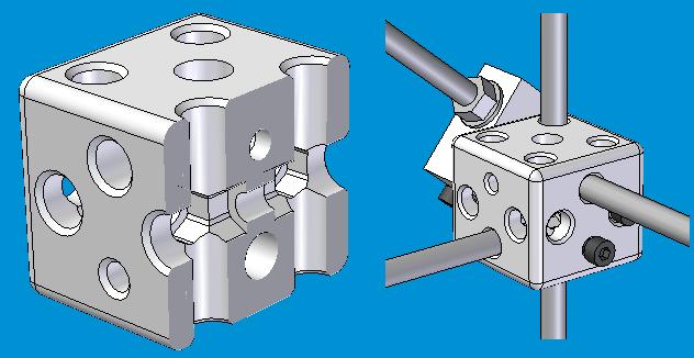
I've started work on an idea for corner brackets to assemble a solid frame for Darwin.

It's 45x45x40mm, symmetrical and provides 'through-hole anchorage' (i.e. the bar passes all the way through the bracket, thus rockhard clamping) for three bars and one bit of studding. Also, if the bolt configuration's right (which is a real mind-job) it also offers 2 expansion holes, 3 without the studding (I think, maybe 4).
I AoI'd it! Which is a big deal for me, as I have been hiding in my familiar Solid Edge hole for a while now, hoping no-one would notice. And it wasn't all that bad! Quite a powerful approach I thought. Though I need Vik's advice on how to do complicated sketches. I STL'd the final version and the Strat's knocking out a prototype nownow...
The design totally lends itself to Simon's magical crystallisation. How do I get that button on my screen? ;-)
Universal PCB
And out of the bubbling ferric chloride bath comes...
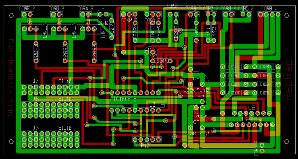
I'm working on that - a single PCB that can be populated to make either the RepRap stepper controller or the extruder controller. Here's what it looks like in Kicad:
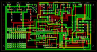
This would make constructing these a lot easier - there would only be one component instead of two, and much less soldering and opportunity to make mistakes.
Now to drill the holes, solder wires in the vias, and add chips...
If it works, it'll go on the wiki as part of the RepRap 1.0 "Darwin" design, which will be the first release.

I'm working on that - a single PCB that can be populated to make either the RepRap stepper controller or the extruder controller. Here's what it looks like in Kicad:
This would make constructing these a lot easier - there would only be one component instead of two, and much less soldering and opportunity to make mistakes.
Now to drill the holes, solder wires in the vias, and add chips...
If it works, it'll go on the wiki as part of the RepRap 1.0 "Darwin" design, which will be the first release.
Tuesday, November 28, 2006
Modesty demands...
...That we not tell you the following quote from Saturday's paper:
"[RepRap] has been called the invention that will bring down global capitalism, start a second industrial revolution and save the environment..." - James Randerson writing in The Guardian on November 25, 2006.
"[RepRap] has been called the invention that will bring down global capitalism, start a second industrial revolution and save the environment..." - James Randerson writing in The Guardian on November 25, 2006.
Faster, Cheaper, Better
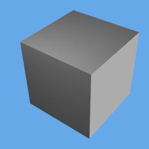
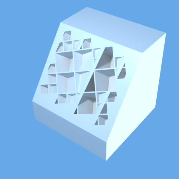
Wow, look what we can model:

Okay, so it doesn't look very impressive.
In a small diversion from updating the comms code I wrote a plugin for AoI that does a kind of 3D tesselation or decomposition of arbitrary shaped objects, removing much of the internals of the object. It is removed in such a way that it can be fabricated additively without any support material, just by allowing for a small amount of overhang between layers. Experiments conducted earlier by Ed and Adrian suggest a 45° overhang is achievable (hence the 45° slope in the RepRap logo).
Although the end result in this case is just a cube, a cut-away view reveals the internal structure:

The code can be extended to arbitrary tesselation shapes, and I've implemented cubic and tetrahedral decomposition to date. The tetrahedral one really still needs some work because as I now realise, you can't completely decompose an object into tetrahedra. There are also some square dipyramids in there too, which mess things up a little bit.
The advantage of the tetrahedral approach over the cubic is that it is a geometrically stronger shape (the cubes should naturally deform more easily, which might be useful in some situations). Also, with tetrahedra the maximum overhang angle is 30° which should be easier to achieve too.
The parameters allow for the adjustment of the minimum and maximum feature size and also the wall thickness. If chosen appropriately, the walls may end up being just a couple of straight lines from the extruder with no infill required. It will significantly speed up the process of making objects, as well as requiring less material and making lighter parts.
This is something you can really only imagine doing with an additive fabrication approach like that used in RepRap, and is potentially very powerful.
The general approach is just to fill the object with the chosen filler "crystals", starting with as large a size as possible (up to the specified maximum) and then filling around it with ever decreasing sizes, down to the minimum size specified:

There are other possible approaches that may also work well, such as a tree like structure that branches ever smaller until it reaches the extremities.
Okay, so it doesn't look very impressive.
In a small diversion from updating the comms code I wrote a plugin for AoI that does a kind of 3D tesselation or decomposition of arbitrary shaped objects, removing much of the internals of the object. It is removed in such a way that it can be fabricated additively without any support material, just by allowing for a small amount of overhang between layers. Experiments conducted earlier by Ed and Adrian suggest a 45° overhang is achievable (hence the 45° slope in the RepRap logo).
Although the end result in this case is just a cube, a cut-away view reveals the internal structure:
The code can be extended to arbitrary tesselation shapes, and I've implemented cubic and tetrahedral decomposition to date. The tetrahedral one really still needs some work because as I now realise, you can't completely decompose an object into tetrahedra. There are also some square dipyramids in there too, which mess things up a little bit.
The advantage of the tetrahedral approach over the cubic is that it is a geometrically stronger shape (the cubes should naturally deform more easily, which might be useful in some situations). Also, with tetrahedra the maximum overhang angle is 30° which should be easier to achieve too.
The parameters allow for the adjustment of the minimum and maximum feature size and also the wall thickness. If chosen appropriately, the walls may end up being just a couple of straight lines from the extruder with no infill required. It will significantly speed up the process of making objects, as well as requiring less material and making lighter parts.
This is something you can really only imagine doing with an additive fabrication approach like that used in RepRap, and is potentially very powerful.
The general approach is just to fill the object with the chosen filler "crystals", starting with as large a size as possible (up to the specified maximum) and then filling around it with ever decreasing sizes, down to the minimum size specified:
There are other possible approaches that may also work well, such as a tree like structure that branches ever smaller until it reaches the extremities.
Tuesday, November 21, 2006
Unexpected twist for new filament
As per our discussions I began breaking up the 3 kg of CAPA filament for shipment this morning. Earlier, Vik had said in correspondence that...
The new filament rotates a lot more in the extruder than the old
filament. A lot more.
I left a rather large model going and went to have a shower. I came back
to find filament wrapped around the support pole I use like bindweed,
and the extruder was gamely trying to suck in support rod and all. I
knew this would end in tears...
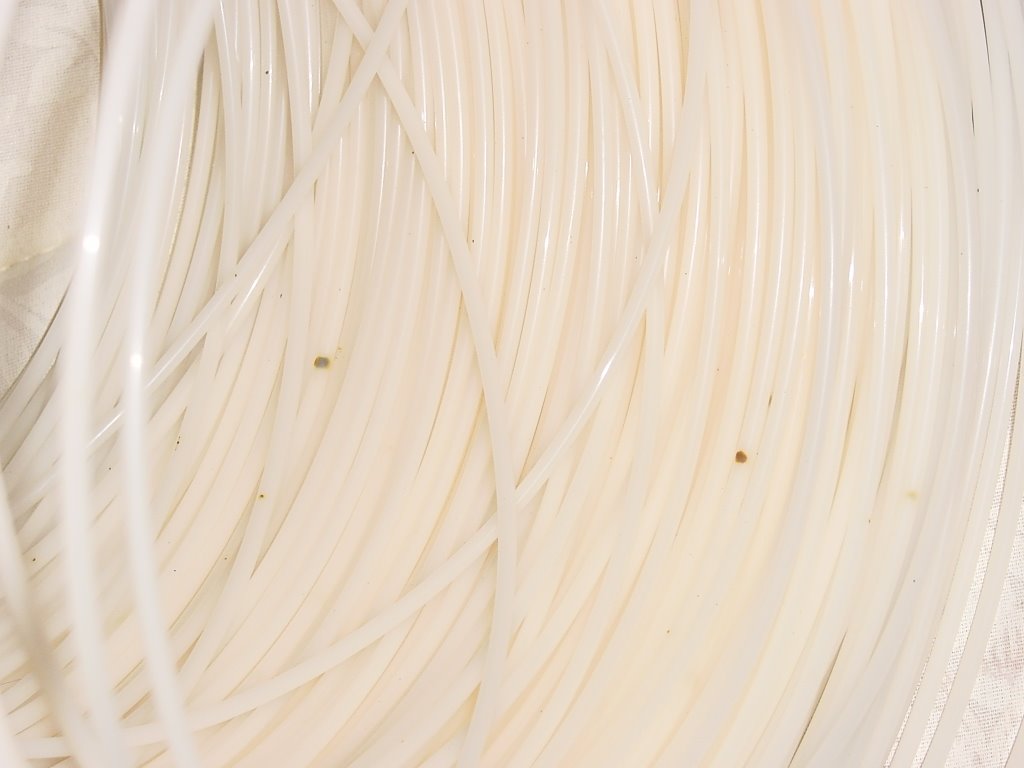
Vik's words came back to me in both bold face and italics when I began making the new coils of the filament for shipment. The filament has a strong memory of the roll it was put into. Left to its own devices it does its best to return to that shape regardless of what you are trying to achieve. In that it behaves a lot like military entanglement wire made of spring steel and a bit like certain garden hoses I have known. For a few moments before I was able to leverage the natural coiling of the filament I had mental images of my body being found on the floor of my flat a week hence in a big, slightly pink coccoon of the CAPA filament.
As well, the inclusions that Vik and Simon reported are definitely NOT restricted to the ends of the filament consignment but a regular feature every few feet in the filament. The inclusions are of two types. The first are friable black flecks that apparently adhered to the filament after it left the extruder before it cooled. The second are embedded inclusions that obviously got mixed in with our polymer when it was dumped into the extruder hopper. I'd suspect that either the extruder wasn't fully clean when they did our run OR that they burned a bit of the CAPA getting the settings right and that the burned flakes got included in the subsequently extruded filament.
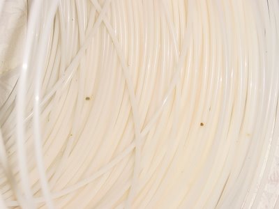
I took a photo of the inclusions which I intend to send to Image Plastics as a starting point for a discussion on these matters. This is something that certainly wants addressing before we place a larger order with them.
I did notice that as I was unrolling the filament from the inside of the coil, which was the first filament extruded the number of inclusions in the filament declined. I did the two 2 lb rolls first and Simon's 1 lb roll last. Simon's looked much cleaner than the previous rolls. This may mean that the extruder had some junk in it which cleared as more filament was produced. I noticed this happening in the screw extruder that I built many months ago.
The new filament rotates a lot more in the extruder than the old
filament. A lot more.
I left a rather large model going and went to have a shower. I came back
to find filament wrapped around the support pole I use like bindweed,
and the extruder was gamely trying to suck in support rod and all. I
knew this would end in tears...
Vik's words came back to me in both bold face and italics when I began making the new coils of the filament for shipment. The filament has a strong memory of the roll it was put into. Left to its own devices it does its best to return to that shape regardless of what you are trying to achieve. In that it behaves a lot like military entanglement wire made of spring steel and a bit like certain garden hoses I have known. For a few moments before I was able to leverage the natural coiling of the filament I had mental images of my body being found on the floor of my flat a week hence in a big, slightly pink coccoon of the CAPA filament.
As well, the inclusions that Vik and Simon reported are definitely NOT restricted to the ends of the filament consignment but a regular feature every few feet in the filament. The inclusions are of two types. The first are friable black flecks that apparently adhered to the filament after it left the extruder before it cooled. The second are embedded inclusions that obviously got mixed in with our polymer when it was dumped into the extruder hopper. I'd suspect that either the extruder wasn't fully clean when they did our run OR that they burned a bit of the CAPA getting the settings right and that the burned flakes got included in the subsequently extruded filament.
I took a photo of the inclusions which I intend to send to Image Plastics as a starting point for a discussion on these matters. This is something that certainly wants addressing before we place a larger order with them.
I did notice that as I was unrolling the filament from the inside of the coil, which was the first filament extruded the number of inclusions in the filament declined. I did the two 2 lb rolls first and Simon's 1 lb roll last. Simon's looked much cleaner than the previous rolls. This may mean that the extruder had some junk in it which cleared as more filament was produced. I noticed this happening in the screw extruder that I built many months ago.
Friday, November 17, 2006
A Printable Penguin
Using the 2.5mm CAPA filament that Forrest had made up, I've produced a 50mm tall penguin for my upcoming presentation at LCA 2007:

It's extruding fine, and the spareseness of the fill is intentional at this point. The deposition is done with Simon's latest version of the code that raises and lowers the head to avoid smears. It works well, but there are small drawing artifacts that cause the head to bounce up and down in the penguin's feet, causing it to look like the RepRap is trying to hammer the polymer in!
Vik :v)
Sunday, November 05, 2006
As he giveth so shall he taketh away
I toyed with a small variation in the code today. Rather than producing an object from the bottom up, I added an option that reverses this so it produces the object from the top layer downwards.
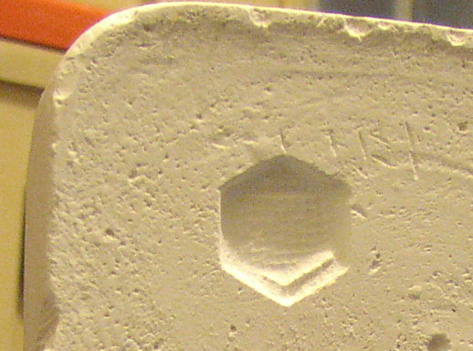
Plug a dremel onto the extruder stage, and suddenly you have a mini-mill.
Throw on a block of plaster of paris, and you can easily cut out molds:
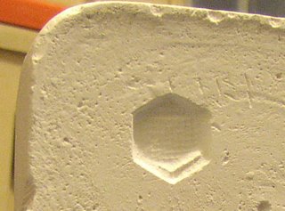
It would be easy to add sprue-points and gates to lock positions, then you could make a double-sided mold that accurately lines up.
Pouring in something simple like molten aluminium could produce some nice metal parts.
Of course it's not the reprap way, but it's interesting nonetheless.
Plug a dremel onto the extruder stage, and suddenly you have a mini-mill.
Throw on a block of plaster of paris, and you can easily cut out molds:
It would be easy to add sprue-points and gates to lock positions, then you could make a double-sided mold that accurately lines up.
Pouring in something simple like molten aluminium could produce some nice metal parts.
Of course it's not the reprap way, but it's interesting nonetheless.
Saturday, November 04, 2006
Test driving the RepStrap
I tried printing a few different simple objects with a 1mm extrusion size today. Here's a two layer hexagon. It seems there are currently a few little glitches with the hatching algorithm, so it's slightly misshaped, but otherwise looking generally good. I obviously still need to tweak some of the parameters a little to eliminate the gaps.
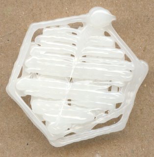
There's still a way to go to catch up to Vik's more true-to-concept machine. Hopefully I will be able to print my own parts for Darwin soon though.

There's still a way to go to catch up to Vik's more true-to-concept machine. Hopefully I will be able to print my own parts for Darwin soon though.
Thursday, November 02, 2006
Extruding -- or not
So I finished building my Repstrap. See http://repstrap.blogspot.com/ for ungainly pictures. I'm quite pleased that I managed to make it entirely from some copper tubing, an old PC and some old roller skates. A few nuts, bolts and electronics parts too of course, but all in all pretty simple.
It is using the L298N driver electronics as well now, which works much better than the others and also provides a lot more torque (and therefore also higher speeds). Which reminds me -- I must wiki that.
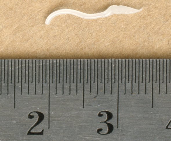
Everything works very nicely. I have run some test objects through it and everything is behaving as it should. My only problem is that the MkII extruder is really not extruding very quickly at all so the results are pretty hopeless. The first test extrusion was okay:
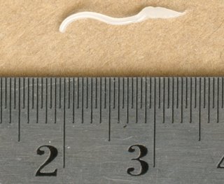
(the dodgy looking end is caused by me pulling it off the extruder)
After it gets moving it has a good 0.60mm output which is exactly what I was aiming for on this first nozzle. However it settles into a pattern of not really extruding much of anything at all. I'm guessing the M3 studding that pulls the filament downwards is stripping the filament after a while and losing its grip.
Has anybody else experienced the same problem? Is it just because I'm driving the extruder motor too quickly? If I drive it a lot slower, does it still extrude okay (sufficient pressure, etc.)? Can I even drive it slowly enough without stalling it? How fast does the MkII really extrude when its working properly (0.6mm dia)?
It is using the L298N driver electronics as well now, which works much better than the others and also provides a lot more torque (and therefore also higher speeds). Which reminds me -- I must wiki that.
Everything works very nicely. I have run some test objects through it and everything is behaving as it should. My only problem is that the MkII extruder is really not extruding very quickly at all so the results are pretty hopeless. The first test extrusion was okay:
(the dodgy looking end is caused by me pulling it off the extruder)
After it gets moving it has a good 0.60mm output which is exactly what I was aiming for on this first nozzle. However it settles into a pattern of not really extruding much of anything at all. I'm guessing the M3 studding that pulls the filament downwards is stripping the filament after a while and losing its grip.
Has anybody else experienced the same problem? Is it just because I'm driving the extruder motor too quickly? If I drive it a lot slower, does it still extrude okay (sufficient pressure, etc.)? Can I even drive it slowly enough without stalling it? How fast does the MkII really extrude when its working properly (0.6mm dia)?
![]()