Saturday, April 30, 2005
Silver Paint Track Trials
Conductive tracks were laid on PVC film with lands at each end. Two sets of three were used; painted tracks, painted tracks with additional paint blobbed on the lands, and tracks with blobbed paint allowed to dry before additional blobs were added.
One set was dried for 12 hours, the other for 30 minutes under a fan and then both were covered in 1mm hot-melt EVA. 0.2mm tinned copper wire leads were pushed through from the PVC side and the resistance measured with a bench multimeter.
The fresher tracks were unreliable, exhibiting infinite resistance except for the plain painted track which was intermittent between 60 and 160 ohms.
The older tracks had an extremely intermittent single track, 17-50 ohm blobbed track, and 5-6 ohm for the double-blobbed track.
These results suggested that the earlier PCB experiment should be redone with double-blobbed lands and that the silver paint is allowed to cure overnight before embedding in EVA.
Friday, April 29, 2005
Hoeken has found more possible CAD input. He writes:
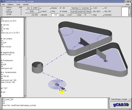
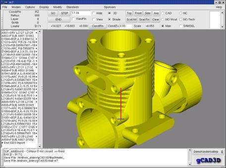
"Just found another 3d CAD project: gCAD3D
the homepage sucks (http://www.cadcam.co.at/freiter/gCAD3D_en.htm),
however if you go to the root directory there are some screenshots:
http://www.cadcam.co.at/freiter/gCAD3D1.jpg
through
http://www.cadcam.co.at/freiter/gCAD3D7.jpg
i'm at work now so i cant really try it out. apparently it has DXF
support, and can also run on windows!!"
He has also tracked down sources of bulk thermoplastics for use in the machine:
http://www.delviesplastics.com/welding.htm
.125" diameter abs (1lb = 160ft.) @ $7.50/lb
gives us $0.31 / cubic inch
http://store.yahoo.com/ecomplastics/750diamblaca1.html
.75" diameter abs @ 3.04 / ft.
gives us $0.57 / cubic inch.
(I can see that the people on this project are going to need to do a lot of multiplying and dividing by 25.4...)
And Vik reports that AoI has STL input/output now. Check out:
http://sourceforge.net/forum/forum.php?thread_id=1273132&forum_id=47782
John Davis e-mails to draw our attention to the following interesting paper:
Hu, Zhu; Hur, Junghoon; Lee, Kunwoo
ABBREVIATED JOURNAL TITLE- J Mater Process Technol
VOLUME 130-131
2002/Dec 20 2002
PP p 378-383
13 REFERENCE
DOCUMENT TYPE- JA Journal Article
ISSN- 0924-0136
CODEN- JMPTEF
AUTHOR AFFILIATION- School of Mech. and Aerosp. Eng. Seoul National
University, Kwanakgu, Seoul 151-742, South Korea
JOURNAL NAME- Journal of Materials Processing Technology
LANGUAGE- English NDN- 267-0409-8560-3
To overcome the limitations of the layered manufacturing process, hybrid
rapid-prototyping systems that allow material removal and deposition are
being introduced. This approach should benefit from the advantages of
conventional layered manufacturing and traditional CNC machining
processes. To realize these advantages, however, an intelligent process
plan must be generated. In the hybrid rapid-prototyping process, a part
is decomposed into thick-layered 3D shapes, such that each layer can be
machined and stacked easily. When each layer is generated from the
part's shape, the build orientation is an important factor to be
considered, because it greatly influences the lead-time, the machining
accuracy, and the number of tool-accessible features in each setup. In
this paper, an algorithm to determine the build orientation is
described. It considers the deposition process attributes and the
machining process attributes simultaneously. $CPY 2002 Elsevier Science
B.V. All rights reserved. 13 Refs.
DESCRIPTOR- Algorithms; Deposition; Layered manufacturing; Machine
tools; Machining
IDENTIFIER- Build orientation
TREATMENT CODE- TC-T (Theoretical)
SECTIONAL CLASSIFICATION CODE- CAL723.5; CAL913.4; CAL802.3; CAL604.2;
CAL603.1; CAL921
SECTION HEADING- Rapid prototyping
We had thought of a half-way-house in powder-printing machines where a powder-filled cavity in the part is vacuumed out half way through a build and filled with another material, such as Wood's metal, or silicone rubber.
Monday, April 25, 2005
With reference to Vik's glue gun idea: I have found out that you can get ABS cylindrical rods for plastic welding (e.g. here). ABS melts around 110 deg C, which means that it should go in a glue gun no problem (especially if you run the gun from a light-dimmer to allow you to adjust the temp). ABS is the plastic of choice for commercial FDM machines. Now all we have to do is to find some of the right diameter...
Monday, April 18, 2005
Vik has tried an experiment with his circuit idea. He says:
"I did a quick experiment with conductive silver paint. I Stretched out commercial PVC food wrap over a box lid and daubed tracks 1.5-2mm wide on it. When the paint had cured, EVA hot-melt glue was applied to cover the tracks in an approx. 0.5mm layer.
"Spare component leads were pushed through the PVC into the EVA via the paint. A resistance of 0.6 ohms was measured across two test leads inserted into circular pads at each end of a 25mm line.
"The pen tip is not a fibre tip, but reminiscent of the old correction ink pens, and the particular one I had was prone to clogging. A syringe-based system may be more appropriate.
"I'll leave the samples for a week and see what happens to them. If all is well, I'll attempt to assemble a simple electronics kit. This should be achievable by stretching the PVC over the copper side of the board,
tracing out the tracks, and pushing the components through. I might mount that one on drilled plywood though."
-----------------
Here is the latest Wood's metal deposition head design from Ed Sells, all made by RP:

(To see the original look at the blog for March 23 2005.) This one has a hot-air heating jacket controlled by a thermocouple thermostat, and drive feedback from the optoswitch you can see at the top of the picture. The whole thing is straightforward to control with a PIC and the rather neat H-bridge BA6286 from Rohm. When I can get myself (and more importantly the data) organised I'll put all the designs and software up on the Documentation section of the website.
-----------------
Thanks to my colleague William Megill for drawing the following measuring device to our attention; he says:
"It's basically two thin copper wire coils set in a sleeve of silicone rubber. As it's stretched, the coils get further apart, which changes the capacitance. Strains up to 150-200% are no problem."
See this link for details.
"I did a quick experiment with conductive silver paint. I Stretched out commercial PVC food wrap over a box lid and daubed tracks 1.5-2mm wide on it. When the paint had cured, EVA hot-melt glue was applied to cover the tracks in an approx. 0.5mm layer.
"Spare component leads were pushed through the PVC into the EVA via the paint. A resistance of 0.6 ohms was measured across two test leads inserted into circular pads at each end of a 25mm line.
"The pen tip is not a fibre tip, but reminiscent of the old correction ink pens, and the particular one I had was prone to clogging. A syringe-based system may be more appropriate.
"I'll leave the samples for a week and see what happens to them. If all is well, I'll attempt to assemble a simple electronics kit. This should be achievable by stretching the PVC over the copper side of the board,
tracing out the tracks, and pushing the components through. I might mount that one on drilled plywood though."
-----------------
Here is the latest Wood's metal deposition head design from Ed Sells, all made by RP:
(To see the original look at the blog for March 23 2005.) This one has a hot-air heating jacket controlled by a thermocouple thermostat, and drive feedback from the optoswitch you can see at the top of the picture. The whole thing is straightforward to control with a PIC and the rather neat H-bridge BA6286 from Rohm. When I can get myself (and more importantly the data) organised I'll put all the designs and software up on the Documentation section of the website.
-----------------
Thanks to my colleague William Megill for drawing the following measuring device to our attention; he says:
"It's basically two thin copper wire coils set in a sleeve of silicone rubber. As it's stretched, the coils get further apart, which changes the capacitance. Strains up to 150-200% are no problem."
See this link for details.
Friday, April 15, 2005
A brief experimental result on the idea of using release agent to separate supports from built objects in FDM. We had our Stratasys Dimension FDM machine make a 10mm ABS cube, paused the build about one third the way through, opened the machine, and painted a thin film of vegetable oil (Tesco's own-brand Corn Oil, to be precise) on the top surface. We then resumed the build, which proceeded as normal.


The first picture shows the finished cube. (The mistake loop is irrelevant - it is about four layers below the split.) The cube split cleanly (second picture) where the oil had been deposited, needing a small but definite force to do so. This means that one could use such a system for deciding splits between support and object in FDM. The oil depositor would not need to be much more complicated than a felt-tip pen...
The first picture shows the finished cube. (The mistake loop is irrelevant - it is about four layers below the split.) The cube split cleanly (second picture) where the oil had been deposited, needing a small but definite force to do so. This means that one could use such a system for deciding splits between support and object in FDM. The oil depositor would not need to be much more complicated than a felt-tip pen...
Thursday, April 14, 2005
More input on the CAD question from Paul (no surname...):
http://www.opencascade.org/
http://www.tech.oru.se/cad/varkon
http://www.tech-edv.co.at/lunix/MODlinks.html
The problem with OpenCascade may be the same as that for BRLCAD - namely that it's a good geometry engine but needs a user interface. The other two links look useful.
And from Sven Johnson there's:
http://www.openarchitect3d.org
http://www.openfx.org/ and
http://www.ppmodeler.com/
And some more neat stuff from Vik Olliver, this time on electrical conductors interfacing with chips. To quote him:
"I wondered if it might be practical to lay down one layer of relatively soft plastic such as EVA, which only needs to be in the places that will be occupied by tracks. A conductive silver paint pen:
http://www.dse.co.nz/cgi-bin/dse.storefront/en/product/N5184
is then run across the tracks. The layer is allowed to cure, and is covered with another protective layer of softer plastic. The board substrate is then printed over the top of the tracks, with holes left where component legs are expected to go.
"Once the board is peeled off the base platform (or a very thin non-conductive layer of platform protectant such as PVC film might be used as the first layer), components can be pushed through the face bearing the tracks, forming a contact between the trapped conductive layer and the component legs.
"The paint also has applications for printing non-durable switch contacts, though a conductive elastomer might be more appropriate.
"Printing the track in plastic first reduces the dependence on the size of the paint pen tip for track width.
I suspect that it might be possible to print a simple digital circuit such as a calculator/PDA using a PIC, printed keyboard, and a serial LCD for the display - all in a snap-fit case."
Wednesday, April 13, 2005
Vik Olliver has just sent us pictures of his marvellous Meccano and glue-gun RP material deposition system. Here they are:


He made this and got it working in six days. He managed to get a 19.5mm diameter tube with a wall thickness of 0.85mm and a height of 16.5mm, and is writing a more detailed description which he has kindly agreed to allow us to post on this site. Glue guns use ethylene-vinyl acetate as a working material, incidentally. Just Araldite a fine very short hypodermic needle into the end of the glue gun, and add some servo axes and a computer...
15 April 2005: Vik has just sent us a draft copy of his report. It's also available from Reports and Documentation at www.reprap.org.
Friday, April 08, 2005
An extrusion head that co-extrudes a thin copper wire filament together with a polymer (like a miniature version of the way that ordinary electrical wires are made) to form electrical connections. The extrusion would bind in with the rest of the RP part.
Wednesday, April 06, 2005
Polymorph might be a useful material. It's a nylon-like polymer that melts around 60oC.
Monday, April 04, 2005
We quite like the idea of building an extra head into an FDM system to dispense polydimethylsiloxane (PDMS - bathroom sealant) together with an optically-triggered crosslinking agent; that way we could make components from rigid insulators, rigid conductors, and a synthetic rubber all integrated together.
Friday, April 01, 2005
Another powder-printing possibility: inkjet pure water onto hemihydrated calcium sulphate (i.e. plaster of paris - or maybe instead even Portland cement... possibly mixed with a fibre filler for strength). The CaSO4 solidifies in a few minutes.
Alternatively inkjet a solvent to fuse a powder; PVA and water might work quite well, or virtually any thermoset and a corresponding organic solvent for it. Thermosets dissolving in propanone (acetone) might be good, as propanone has a high vapour pressure and so would evaporate quickly and is not that toxic in a well-ventilated area (it's nail varnish remover).
Alternatively inkjet a solvent to fuse a powder; PVA and water might work quite well, or virtually any thermoset and a corresponding organic solvent for it. Thermosets dissolving in propanone (acetone) might be good, as propanone has a high vapour pressure and so would evaporate quickly and is not that toxic in a well-ventilated area (it's nail varnish remover).
![]()