Wednesday, January 28, 2009
Support for overhangs

The latest Java host program in the repository now contains code to compute the support needed for overhangs automatically. Above is a screenshot of it working - the L block bottom left is being deliberately built the wrong way up so that it needs support. The layer currently being computed is shown in the diagnostic window. You can see the cross-section of the object itself (blue) and the support for the overhang (brown).

Here it is part-way through the build. You can see the support pattern at the front, and the pillar of the L-shaped object being built at the back.

Here is the build finished. The supported bit is at the front.

Here is the part after taking it off the machine viewed from underneath with the support still in place.

And here it is in its final form with the support separated.
The program allows you to specify a support material for each material in the RepRap machine by name. As the RepRap code allows you to have several logical extruders all talking to the same physical extruder you can use a material to support itself by copying its entries in the preferences file (sort the file first to bunch them together) then renaming them from Extruder_0 to Extruder_1 (or whatever). You then change the infill pattern of the support to whatever you want. Here I set it not to outline, only to infill, and not to change the direction of the ply between layers.
The support cleaved pretty easily from the part with a penknife blade, but I suspect that this would have been harder had the underside of the part been undulating rather than flat. Of course two extruders would allow - for example - a friable paste to be used as a support (my current favourite: cornflour mixed with a gel of PVA glue and methanol - to be blogged when I have some results...).
The supports are only computed by the host software when it is saving G-Codes to a file. The reason for this is that the software has to do the calculation in reverse - from the top down - so that it can know what's immediately above the layer it is currently creating. It can only do that by writing each layer as a temporary file, then concatenating them all in reverse order to actually build from the ground up when it has finished.
If you are interested in how the use of a CSG representation makes the support calculation easy to code, take a look at the
private void supportCalculations()function in the class LayerProducer.
As you can see, I have not exactly tested the code on the world's most complex shape, so all this should probably be regarded as experimental...
I'm off for a week to give RepRap talks in Wales and then Spain. When I get back I'll try it on something a bit more challenging, and when it's working properly we'll do a release.
Labels: host, java, overhang, support
SolidEdge Version Poll
Hi! You may already be aware we're allowed to use Solid Edge under an academic licence for development. The current version of model file releases is under v19. However, I'd like to move to v21 as I'm getting stability issues with v19, however, I don't want to do that if it's going to alienate any SolidEdge modellers out there (you won't be able to open v21 files from v19).
So now's your chance to put it on hold (-> comments please). I'll give it a month - if I don't hear anything I'll move to v21.
So now's your chance to put it on hold (-> comments please). I'll give it a month - if I don't hear anything I'll move to v21.
Tuesday, January 27, 2009
CSG Evaluator plugin V1.1
Just a quick note to say that the CSG Evaluator plugin to Art of Illusion can now be installed using the Script and Plugins Manager from within Art of Illusion.
It's also tested to work with the recently released version 2.7 of AoI.
Just a quick note to say that the CSG Evaluator plugin to Art of Illusion can now be installed using the Script and Plugins Manager from within Art of Illusion.
It's also tested to work with the recently released version 2.7 of AoI.
Conserving MCU pins via the I2C bus
In which your narrator finally gets around to demonstrating something he's been talking about for the better part of a year... do you want to hear more?
Thursday, January 22, 2009
3D printing on Facebook
Reprappers may care to know that there is a new Facebook page for the 3D printing community called SME Rapid Group. If you're on Facebook, why not join?
There's also the Rapid Prototyping Electronic Mailing List at http://rapid.lpt.fi/rp-ml/ that you can join too. That's been around for a while.
There's also the Rapid Prototyping Electronic Mailing List at http://rapid.lpt.fi/rp-ml/ that you can join too. That's been around for a while.
Labels: community, Facebook, mailing list
Tuesday, January 20, 2009
Going high risk steampunk
In which your narrator finally gets stuck into exploring other prime movers for future reprap machines... do you want to read more?
Labels: "Clanking Replicator", fluid logic, fluidics, hydraulics, pneumatics, Tommelise
HACDC RepRap Buildathon
 This weekend, I'll be heading down to DC and leading the build portion of a RepRap workshop. If you're in the area, you should stop by! Its free!
Join the HacDC and and the Baltimore/Maryland RepRap User’s Group (RUG) for a weekend of RepRap fun! Save the weekend of January 24/25 for our RepRap Build-a-Thon. Initial plans include a range of activities, including hands-on group construction a RepRap Darwin from the ground up starting with laser-cut acrylic parts. We are also planning on having several local RepRap builders on hand with their machines, and hopefully able to demonstrate them in operation, making stuff!
More info on the HacDC website.
Almost immediately afterwards, I'll be hopping on a plane for Madrid to run a 3 week, intensive RepRap workshop with Medialab Prado as part of their Interactivos Garage Science project. If you're in Madrid, you can apply to be a collaborator. Also, our very own Adrian Bowyer will be giving a talk on how awesome digital fabrication is.
Wahoo!
Monday, January 19, 2009
4 Dimensional RepRap
No - we're not doing an open-source time machine. When we get round to that we will do it last year.
This is a more prosaic idea prompted by G Codes and the fact that several people are doing stepper-motor-driven extruders or ones using Zach's neat shaft encoder. I hope I haven't stolen it from Nophead and recycled it as my own idea...
Clearly if you have a stepper extruder there is a precise relationship between the length in mm of filament extruded and the number of steps (this ignores time delays, melt compression and so on - run with me on this). So, why not incorporate the number of mm of filament to extrude as a dimension on each movement? You'd have things like
G1 W50.0 X30.0 Y40.0 F560.0
Where the W coordinate is the number of mm of filament to extrude. This could either get bigger and bigger as a build progresses (we're not going to run out of floating point numbers...) or we could have a convention that zeros it before each move, so it's Pythagoras on the X and Y numbers.
With that we can then control the machine with a 4D Bressenham DDA, which is just as easy to write as the current 3D one and takes hardly any more microcontroller space.
We can then obviously play tricks to get more or less extrudate:
G1 W100.0 X30.0 Y40.0 F560.0
would make a fat splongy line and
G1 W25.0 X30.0 Y40.0 F560.0
would make a jejune one. You can run the extruder without moving to take up any slack:
G1 W10.0 F560.0
and of course you can move with it turned off by omitting the W value altogether.
I'm not sure if this is:
- Clever,
- Dumb,
- Obvious, or
- Useless.
Labels: Bressenham DDA, G Codes, microcontroller
Saturday, January 17, 2009
Pinch Wheel Extruder Is Alive
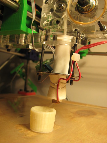 After I got the Pinch Wheel extruder working reliably, the obvious next step was to actually print something with it, right? I spent the past 2 days doing just that. I'm a big fan of Enrique's Skeinforge program, and I used that to generate the GCode for printing a minimug. It took me about 10 tries before I homed in on the proper settings, and they're still not quite right. Skeinforge is an excellent program, but there are a ton of settings that I just don't understand. Hopefully as I use it more, they will become clear to me. If anyone has some tips or tricks, please let me know.
Anyway, here was my process:
1. Use science* to get a feel for the extruder properties. I measured the ooze-rate after I turned the extruder off, and also the length of filament extruded at a certain speed for 60 seconds.
2. Put these measurements into a document to calculate extruder flowrate, etc.
3. Input these values into the Skeinforge program
4. Do a test print, tweak Skeinforge properties to improve build quality.
5. Rinse and repeat.
* for very loose definitions of science
Of course, it wasn't without its mishaps. Here is a short list of things that went wrong:
1. Don't extrude onto superglue on acrylic. The filament attaches really well. I mean really, really well. I destroyed my best print getting it off the acrylic :(
2. Don't use short lengths of filament. The new piece of filament tends to go to one side, while the other filament goes to the other side, jamming things up. Always extrude from a continuous length of filament, like from a spool. If you have to change filament, loosen the idler wheel, and pull out the old filament while its still molten so that the new stuff goes all the way to the melt zone un-impeded.
3. A good tightness is when you can see individual 'stretch' marks on the plastic from the gear teeth. This is also a good indicator of progress as they look like tick marks and the acrylic is clear. A bad tightness either produces small notches (too loose) or will creak and turn the whole filament the 'stretch mark' white (too tight).
4. The extruder *can* destroy itself. When feeding filament the first time, make sure you cut the end to a point with some wire cutters. this helps it self-feed. Watch to make sure it doesn't follow the idler wheel and that it does down its proper channel into the PTFE. If it doesn't, simply loosen the idler wheel, remove the filament, cut the 'chewed' part, and try again. I didn't destroy my extruder, but that's because I paid close attention.
5. If you haven't used your RepRap machine in a while, make sure you oil the bars and threaded rod that need to be smooth. This really makes a big difference in both noise and print quality. For example, I've been fighting with extruder designs for a couple months and have not done much printing. My machine was covered in dust and crap. Giving it a good once-over really did wonders.
6. If the extruder does jam, the teeth will carve out a little 'semi-circle' of plastic on the filament. To fix this, you simply loosen the idler wheel (notice a pattern?) and remove the filament. Cut it to a smooth place with wire cutters, re-tighten the wheel, and re-feed it into the extruder.
Anyway, today was a successful day! My extruder didn't give me any problems. It was rock solid, and very easy to use. The extrusion rate was very nice... very little variance at all. This is mostly due to the gearing and the high torque of the motor. I didn't even need to use a rotary encoder, although there is the option.
Also, the feedrate was very good! I'm using the smallest metal timing pulley that SDP-SI.com supplies, and I was getting about 16mm/sec feedrate @ 0.64mm diameter (960mm/minute). With a larger pulley, I could undoubtedly get a higher feedrate.
Yay!
CSG Evaluator - An AoI plugin for convenient Boolean Operations

The guys over at Metalab have been kicking butt on RepRap related stuff for a while now. They just posted a new blog entry about a plugin for Art Of Illusion that makes it easy to do lots of boolean operations. This may just be the thing that AOI needs to make it easy for people to design printable designs easily.
Read more on their blog entry.
Friday, January 16, 2009
After Darwin: Should Mendel be a specific 3D printer or a technology toolbox?
In which your narrator suspects that we are using the wrong model of evolution... Do you want to read more?
Pinch Wheel Extruder Prototype v1.1
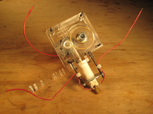
Update on the pinch wheel extruder v1.1 design: It works! It works really really well. I'm a happy little daddy.
I posted the initial design a few days ago, which was just the filament drive portion. Thanks to the wonderful RepRap community, I received a bunch of very excellent design suggestions! I've implemented as many as I can, and updated the design with a whole bunch of improvements. The result is an extruder that is much more powerful, easy to operate, and safer than the standard designs. Here are a few of the changes:
1. Complete Extruder Design
I borrowed the mounting design / heater assembly from my modification of Ian's lasercut extruder. This makes it easy to mount the extruder on a reprap, and easy to mount the heater to it. It is now a fully functional, complete extruder design!

2. New Gear Source
Thanks to Corwin, I found pretty much the perfect drive component from sdp-si.com: It's 10.3mm OD, 6mm bore and it fits *perfectly* on the motor shaft. It even has flanges to guide the filament! Additionally, the teeth are much sharper and deeper than the pulleys that I got from McMaster. What a nice bonus! It is part #A 6A51M017DF0306 if you're interested.

3. Lighter Design
I lightened the design and added cut-outs of non structural components, so the whole extruder clocks in at 1.25lbs, or ~560g. The bulk of this is the motor, which is about 260g, I think. I ordered a few lighter motors from 120g - 200g which should drop the weight down even more. Regardless, I hooked the extruder up to my RepRap machine and it had no problems moving that amount of weight around.
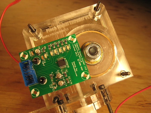
4. Easy electronics mounts!
As a super awesome added bonus, I modified the design to make mounting the electronics to it stupidly easy: First off, the magnetic rotary encoder board will mount directly to the board to give you super precision control over the motor speed. Secondly, I made the four corner bolts to be exactly the proper spacing for the new Extruder Controller v2.0 board which I'll have prototypes coming for in the next week. I don't want to leak too many details yet, but its going to kick some ass: onboard atmega168, so it'll 'be' an arduino, screw terminals for motors, pwm, etc, and RS485 for error free comms to the motherboard. It will mount directly to the extruder, and you can easily wire everything up to the board. Then the only wires you'll have trailing back to the motherboard are power and comms. Yay!

5. LED Mounting Holes
What design would be complete without the option to add some LEDs? Well, the design now has two holes that you can easily and simply press-fit some 5mm LEDs into for a nice backlit / edge lit clear acrylic action. Combined with the weight-reducing honeycombing, there will be some very gorgeous reflections going on. Beautiful and Powerful. Yay!
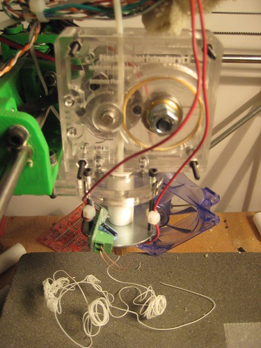
Did I mention it works?
Yeah, I fired it up last night and had a do-or-die moment where all my hard work the past 5 days was on the line. What happened, you ask? She performed flawlessly!!!!! The motor had absolutely no problem keeping up with the extrusion. The gear didn't slip a bit, and the extrusion rate was rock solid, even without an encoder to provide feedback. The fact that the motor is geared down so much means that it has a very steady speed. This translates into very steady extrusion. I went through a meter of ABS like butter. I was too excited to take measurements, but the initial test showed that I can extrude at what looks like speeds from 8mm/sec up to 15-20mm/sec. I'll be measuring extrusion rates today. Will post more info later.
Anyway, now I need to really thoroughly test it, make some prints with it, and get it ready for production. You can get the designs on Thingiverse, or in RepRap subversion. There are a TON of pictures in my flickr set as well. I'm going to Madrid for 3 weeks to run a RepRap workshop, but I'll try and get kits up as soon as I get back in mid-February. In the meantime, beg, borrow, or steal your way into a laser cutter if you want one.
Wednesday, January 14, 2009
MiB

No, not Will Smith, but reprapper Ian Adkins of Bits form Bytes at the BETT 2009 Show at Olympia in London with his latest version of RepRap, which is being sold as a kit into the education market and elsewhere by Unimatic Ltd. It's based on his previous lasercut version but with some neat additions, like a better extruder and a built-in filament reel. It's also driven by PIC32-based electronics that Ian's developed. All designs etc. will be posted online as soon as we get our breath back.
If you're near London why not drop in? It's just up the road from Earls Court tube, or get the special exhibition train to Olympia.
Labels: lasercut repstrap
Monday, January 12, 2009
Pinch Wheel Extruder Prototype
 Ever since reading Lou Amadio's blog entry on an idea for a pinch-wheel extruder, I've had the idea stuck in my head. One of the consistent problems I've had with building a RepRap has been the extruder mechanism: its either super complicated, needs machined parts, or usually a combination of both. When I saw the simplicity of this design, I instantly loved it. However, I didn't know what motor to use on it, so the idea went into the 'rock tumbler' portion of my brain.
Before even starting a design, I wanted to make sure that it was feasible. Going to a direct drive of the filament means that you need a motor that goes really slow... but how slow? Well, glad you asked. I created a Google Spreadsheet with formulas relating to filament feedrate. There are three different things I looked at: Driven Screw based extrusion (how things are now), Pinch Wheel Extrusion (what i wanted to experiment with) and finally how the filament feedrate actually translates into extruded filament. Luckily for me, nophead had posted most of the formulas to the reprap mailing list, so I just had to setup the spreadsheet.
So, what did I find out? Pinch wheel extrusion *is* possible, but you need to hit two important criteria: 1) an RPM of 2 or less, and 2) a pinch wheel diameter of less than 15mm, ideally under 12mm. At these numbers, you get 1.26mm/sec of filament extrusion. With a 0.7mm nozzle, you get 23.08mm/sec of extrusion. This is really fast, but thats okay.
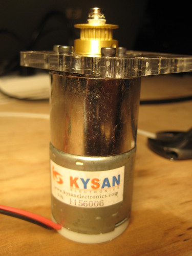 This was all just a random reprap idea in my head until a few days ago, when I got a shipment of DC gearmotors from Kysan. Randomly, I managed to pick up an extremely lucky motor: it is geared down something like 600:1 and thus rotates at 2 RPM. This also means it has a lot of torque. I started on a filament feed prototype yesterday and got a working model.
Unfortunately, the model had some flaws! I really had no idea what to use for the actual pinch wheel. I tried about 5 different things until I found one that worked reliably. I'll list them below so you can learn from my mistakes:
Fail: Acrylic wheel w/ a rubber band glued on. I figured since rubber grips on ABS pretty well, it would work okay. It didn't. It slipped when I applied any sort of 'realistic' force.
Fail: Acrylic 'gear': I tried a variety of lasercut 'gears' with little teeth cut in a variety of profiles. If I didn't push the idler wheel in tightly enough, they would just slip. If I pushed it in too tightly, they just cracked and broke.
Fail: Dremel sanding wheel. I noticed a sanding wheel from a Dremel laying around. It was slightly bigger than the shaft of the motor, so I used a dab of hot glue to attach it to the shaft. I figured that at such low speeds, it would simply grip the filament... which it did. Until it slipped, then it just turned into a super-slow filament sander, lol.
Fail: Tiny belt pulley from McMaster. This pulley wheel was the proper diameter, but the hole to mount on the motor was too small. I decided to drill it out bigger. Well, I basically destroyed the belt pulley.
Win: Slightly larger belt pulley from McMaster. This pulley wheel had a 1/4" (6.35mm) bore which was just slightly bigger than the 6mm motor shaft. A bit of masking tape to keep it properly aligned and it fit perfectly. It has set screws, so it is *very* firmly attached, especially with one set screw on the flat of the motor shaft. This setup was super strong. I had to use quite a bit of man-force to keep it from pulling the filament in. Seriously awesome.
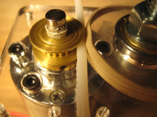 If you look at the pictures, you can see that the pulley wheel actually imprints its tooth profile onto the plastic, which turns the plastic into a sort of matching gear, giving it some serious grip strength. I think that this is the key to getting a good, solid filament drive. There are a few downsides to the pulley: 1) its slightly too big, but McMaster doesn't sell a smaller pulley with the same bore size. 2) the tooth profile is not very sharp. with a sharper tooth profile, it would probably have a much better grip vs the blunt profile.
I'm very happy with how this design turned out: it has very strong filament output, it is a *super* simple design, and everything except the lasercut parts are things you can buy on McMaster.com (or hardware store)
The next step is to modify the design to mount the heater barrel stuff to it, but that should be easy since the lasercut extruder design by Ian has a really nice design for that already.
Oh, and I need to do 2 other things: 1) modify the design to allow super easy mounting of the magnetic rotary encoder and 2) modify the design to allow super easy mounting of the new extruder controller board, which is in prototype stage right now.
Anyway, if you want to check out the design files, they're up on Thingiverse or in RepRap subversion in my home directory.
Cheers!
Zach
Saturday, January 10, 2009
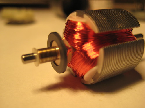
We've been using GM3 gearmotors for our RepRap extruder motors, but they have a few problems (most notably being underpowered and having cheap plastic gears) so I decided to shop around and try to find a motor that I could be proud of. I stumbled onto the site kysanelectronics.com and ordered a bunch of their 12v DC gear motors. I got about 10 different motors with various gear ratios, sizes, etc. I decided to sacrifice one and take it apart. Turns out I was actually (miraculously?) able to piece it back together again, in working order too!
Here is a flickr set with the teardown.
Anyway, here are a few observations about these motors:
* they are all-metal construction (gears, housing, shafts, etc) the only plastic was an insulator on the terminals
* they are very powerful (my test is attaching vice grips and letting them rotate the vice grips, then trying to stop the rotating pliers with my hands. all could easily move the pliers, and most took a decent amount of force to stop)
* they are pretty cheap! for a single motor, they are $9.07 for a single unit and at volumes of 100+ they drop to $7.34. Not as cheap as the GM3, but they have dramatically higher strength, etc.
I think I may just have to place an order for a hundred of them. =)
Friday, January 09, 2009
IRC Chat Now Has An Archived Log

Matt Chan has kindly set up a logging daemon, so we now have an IRC chat archiver!
All messages sent to the #reprap channel on freenet.org will be recorded and archived online at http://mattchan.homelinux.net:55555/reprap/ .
The bot is an eggdrop client (http://www.eggheads.org/) running on a CentOS 5.2 server. More features are expected in the coming weeks.
If you have the Chatzilla plugin installed, just click on irc://irc.freenode.net/#reprap to join in the realtime chat on all things RepRap.
Vik :v)
![]()