Thursday, June 29, 2006
ARNIE gets studding, and goes up...
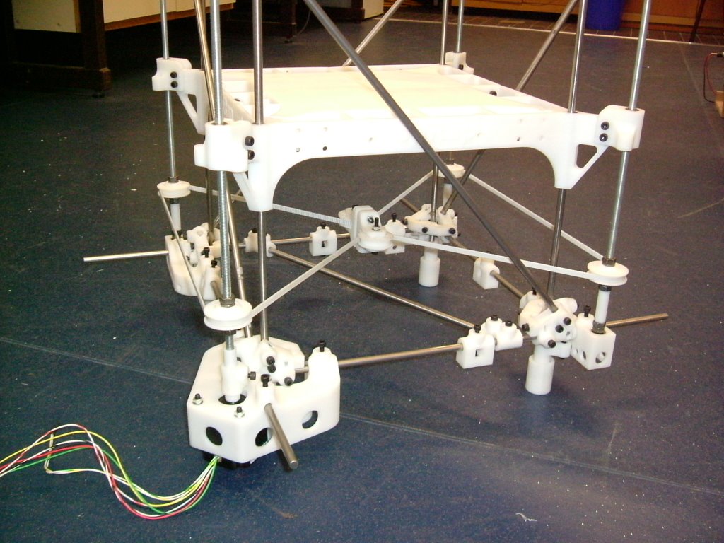
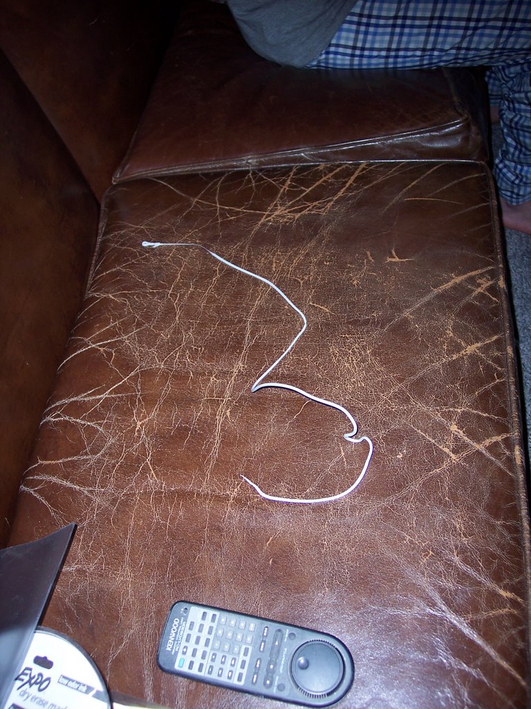
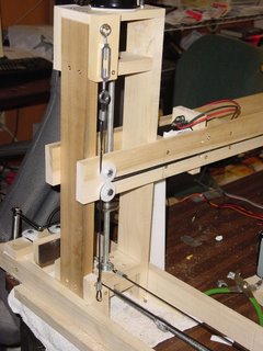
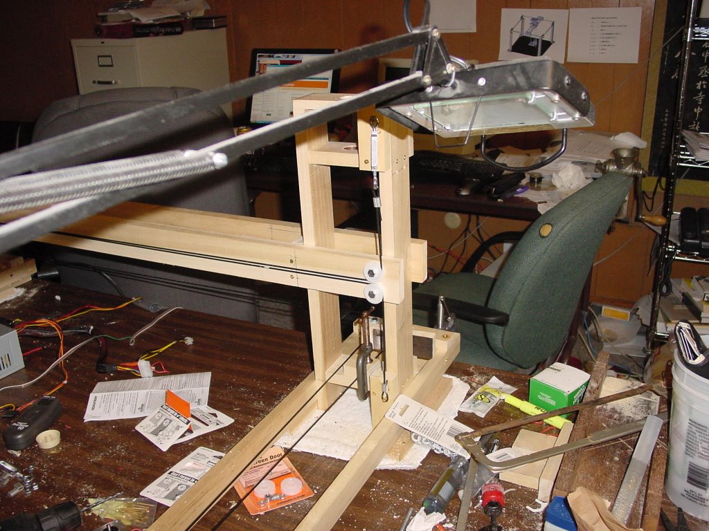
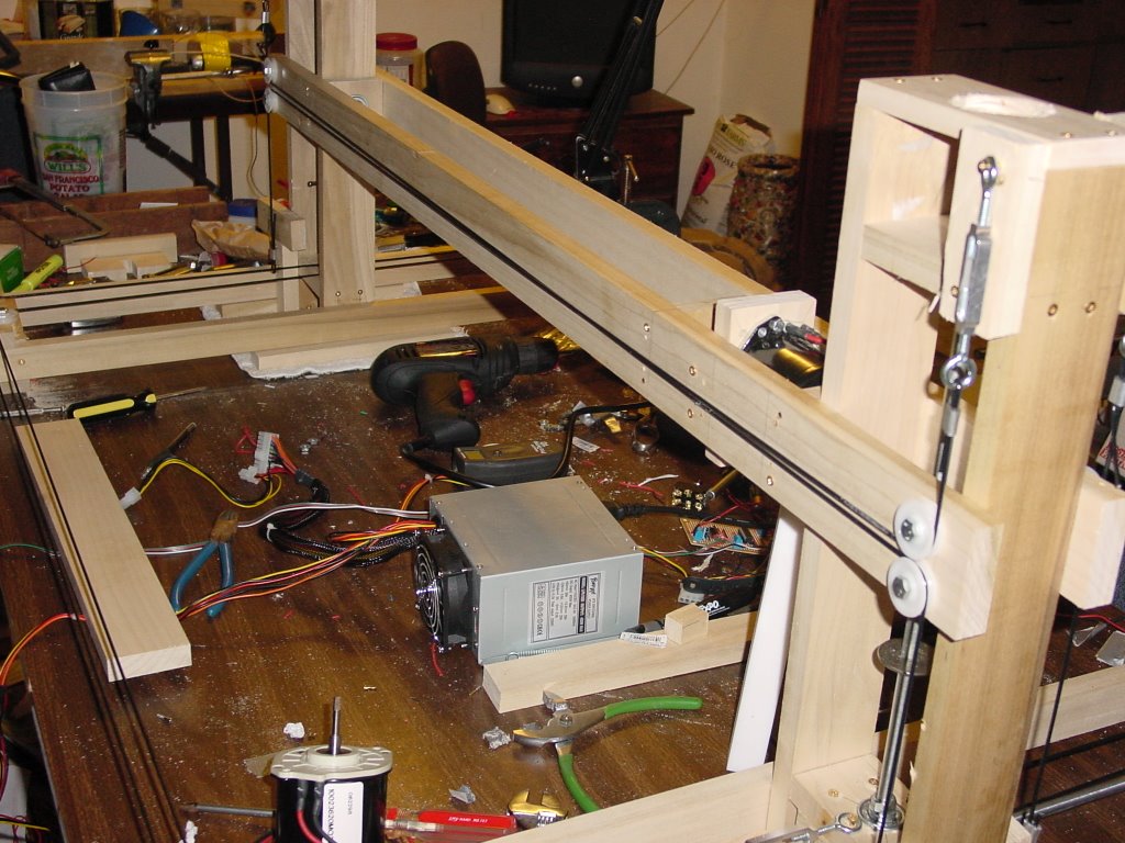
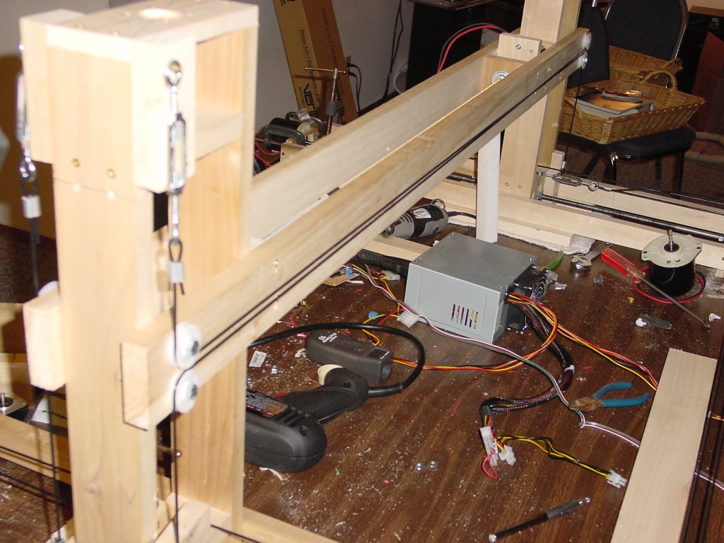
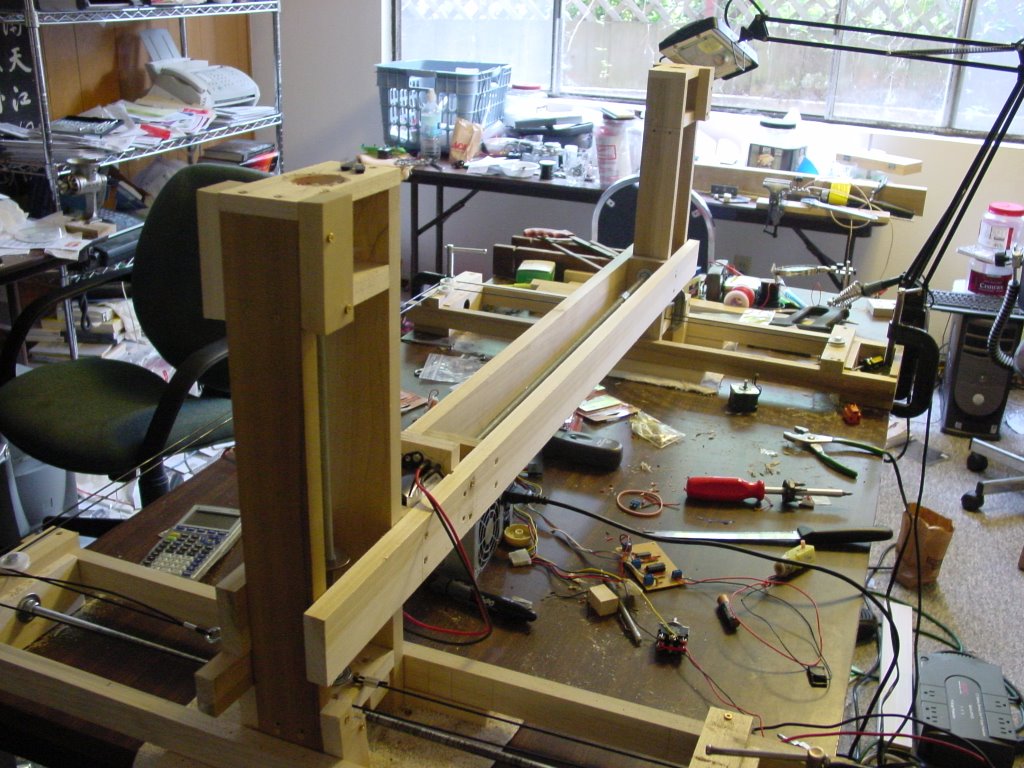
So the string idea got binned. And now ARNIE (mk 2) falls in line with Vik and Forrest's creations... the z-bed is now powered with a studding transmission!
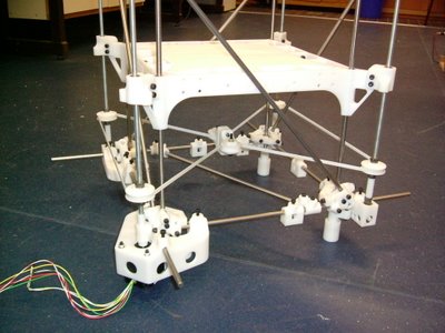
It's a retro fit to mk 1, and so hideously bulky, but very repeatable and reliable. It's a good proof of principle for this arrangement before we move on to Mk 3 which now will certainly use studding for the verticle tranmission.
String's still in the wings for ARNIE's x&y because of its potential speed (compared to screw threads). Hopefully that'll put the rapid into RP.
Tuesday, June 27, 2006
0.5mm Layers and Cooling
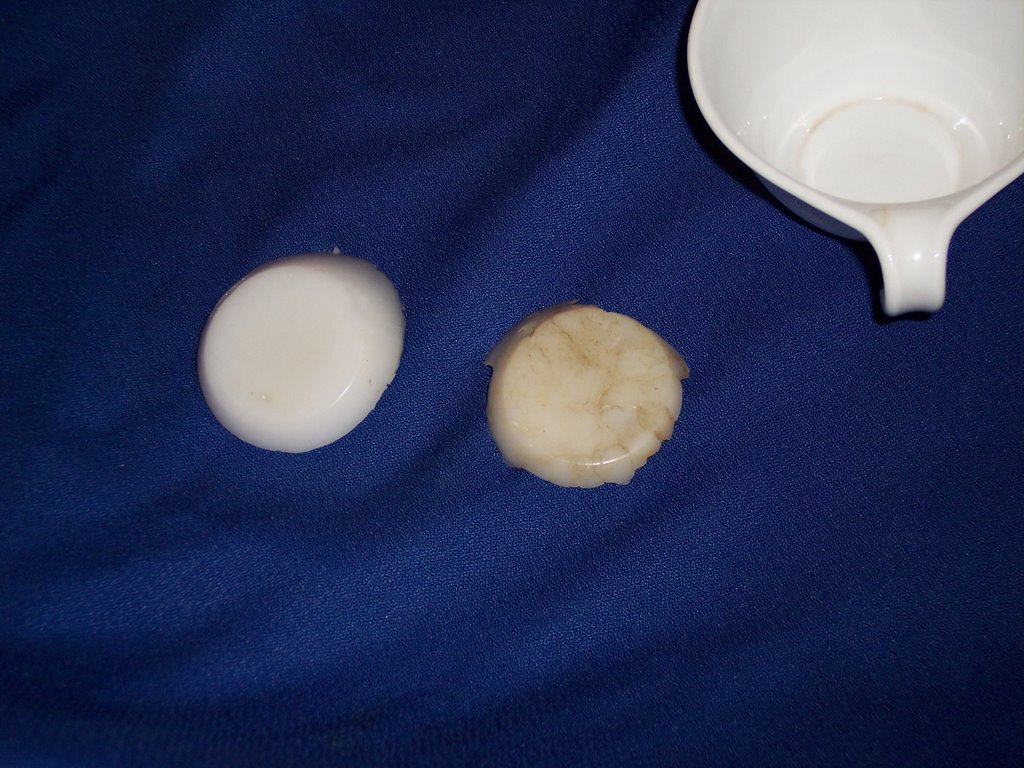
I'm back on light duty after a lower back injury, and firing up the experiments. In the picture below, you'll see two 16mm test hexagonal prisms, now being extruded from layers a mere 0.5mm thick. The one on the left was done contiguously, the one on the right was sprayed with freezer spray to completely solidify it between layers:

Unfortunately, the cooled one detatched from the base and tried to impale itself on the nozzle, so I had to halt the experiment. However, you can clearly see that the distortions are drastically reduced when the lower layers are cooled, and fusion is still good. Hopefully, this will lay to rest any concerns that we might have to do the deposition in a heated environment.
I see Simon has already added a reserved output pin to the PIC for driving a fan in the Wiki. Over the weekend I plan to test deposition on sandpaper, and to try and roughen the glass surface with hair spray. I've tried crosshatching the glass with a diamond scriber, but that didn't seem to help as per above.
Vik :v)
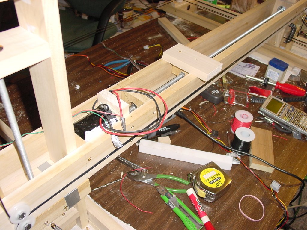
Setting up for shaft encoding tests
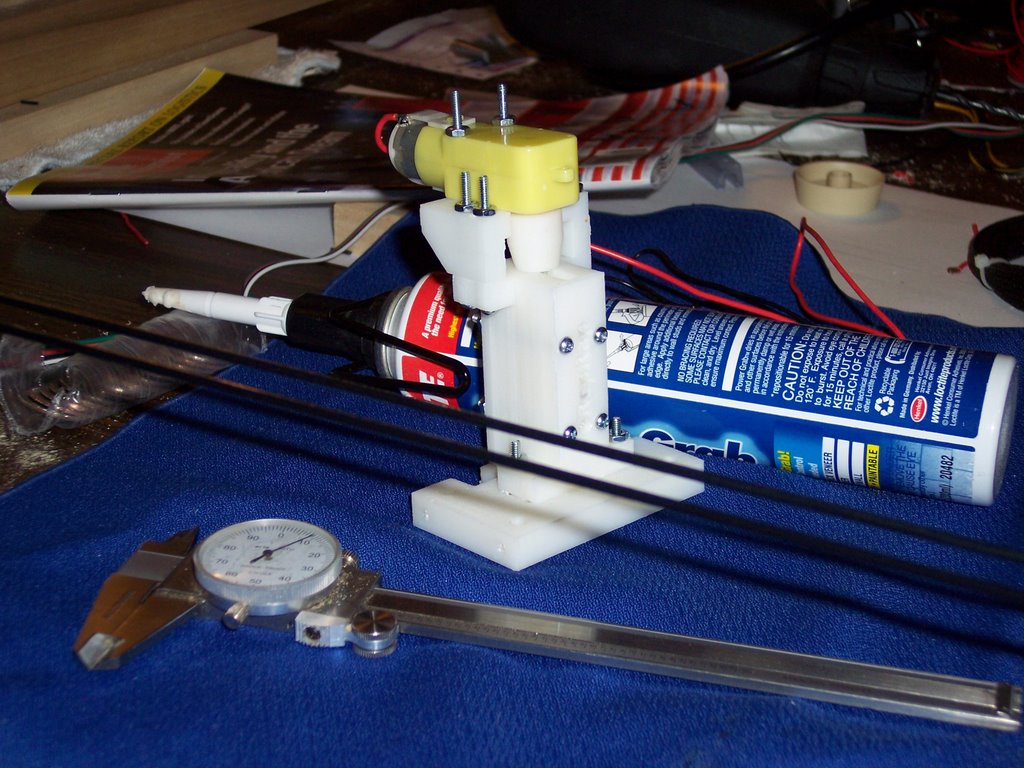
I finally got my nerves steady enough to do the fiddly soldering for the Austriamicrosystems magnetic shaft encoder. I used thin copper filament that I liberated from some #20 multifilament copper wire for the connections.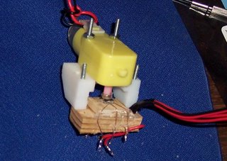
I'm hoping that before the end of the year I'll be able to whip out polymer parts with Godzilla like Adrian does with the departmental Stratasys. For now, though, I'm repstrapping everything, so I used some scraps of Japanese plywood cut from a throwaway wood tray that I got with a log of naruto (Japanese fish cake).
Silicone caulking secured the chip and both insulated the filaments and gave them a firm footing on the bulkhead so that I could solder leads back to the controller board. I also used the same tube of silicone caulking to seat the magnet on the drive shaft. That caulking is nice stuff in that it allows you to attach things to each other without marring their surfaces. When I want that encoder chip back all I have to do is peel the silicone off of it. :-)
I've got a consulting deadline to meet before I can get back to doing the programming for this. It will probably be the weekend before I'll have a chance to get at it. Hopefully, I'll be able to test some programming for those Hamamatsu chips for limits detectors as well then.
Randy got busy doing something so I still haven't heard back on when my L298N dual darlingtons will be shipped or whether he's going to put the 16F877A's in the same shipment. I hope Radio Shack still has some heat sinks and that they'll go with the L298N's. The darned heat sinks cost as much as the chips. :-(
Sunday, June 25, 2006
Got direction and speed going for the little yellow G4 motor...
I'm beginning to get the knack of writing hex code in Oshonsoft Basic. My code is still probably a LOT more awkward than it could be, but I'm getting the job done. :-D
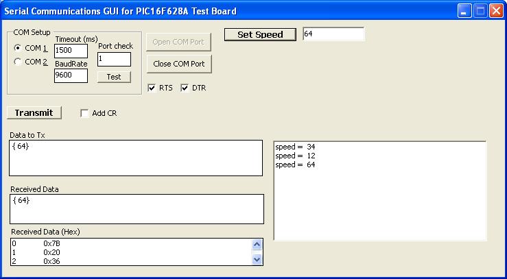
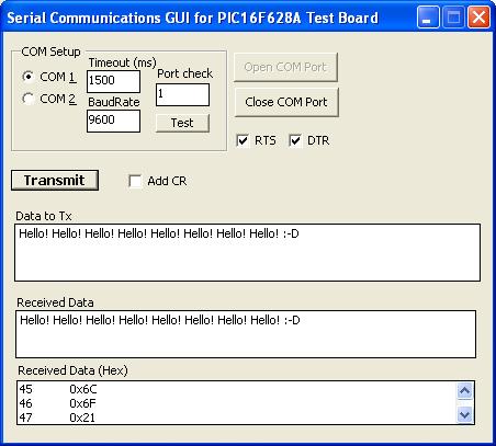
Taking a cue from Simon's bipolar stepper programme I put a slider bar in my VB.NET serial comms programme to control speed and radio buttons to control direction.
 The API for doing the job is extremely simpleminded and intended only for this bit of testing. What gets squirted out on the serial loop looks like...
{(direction, +/-)(speed, 0-255}
A typical command to tell the control board to rotate the G4 counterclockwise at a PWM setting of 200 would look like...
{-200}
The BASIC code to set direction and speed can be got from my personal server for anybody who's interested in looking at my retarded firmware programming style. :-)
If you want the VB.NET code let me know in the comments on this blog entry and I'll zip up a copy, put it on my server and post a link. I personally think that it's way too early for anybody to try emulating what I'm doing. It might not even be a good idea. :-s
Friday, June 23, 2006
MELabs USB PIC programmer board arrived...
YEA! The new programmer board arrived! :-D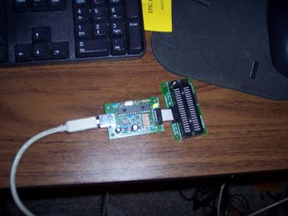
Better yet, all of those dead PIC16F628A chips weren't dead after all, so now I have LOTS of PIC chips! I've beem reprogramming them with good hex files and testing them. :-)
It was definitely something wrong either within the JDM board or the two PC's I tried to run it on didn't provide enough voltage to properly program PICs. I suspect that it was that last.
From what I've been able to read the USB port has a more reliable source of current that can tapped for programming than the RS232 port does.
As well, the new board uses a USB port which means I don't have to crawl around under my desk hooking up RS232 connectors any more.
Now I can see if I can get the motor controller routine and the serial comms routine working together on the motor controller board. It will also be fun to try to get the AS5035 magnetic enconder chip going, too. :-D
Happy Birthday to ME! :-D
Wednesday, June 21, 2006
More work on the Mk IIa...
I had a few moments and made up the threaded drive shaft for the Mk II out of 1/4-24 threaded rod.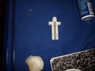

First try at filament...
I got up early and made the little poplar piston after a bit of sawing, rasping and then fine shaping with my Dremel hand tool. I had a piece of scrap poplar left over from a particularly clumsy attempt to make a Frankenmotor mount that worked as a seat for the extruder barrel.
Here goes...
Here's a view of the very complex 2.77mm extrusion orifice....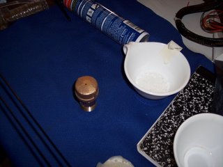
...and the super sophisticated method for avoiding dribble during the heating cycle.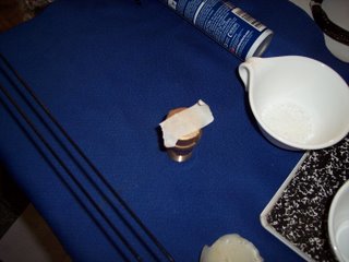
...and how I'm going to keep it upright in the toaster oven.
Now we prep to charge the extruder... ...very tricky...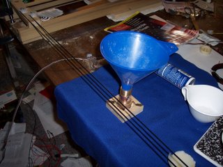
A tablespoon was used for charging the extruder barrel...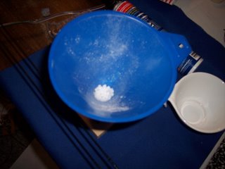
Here you can see the famous toaster oven with the extruder inside and the IR thermometer laying on it's door.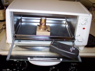
And away we go...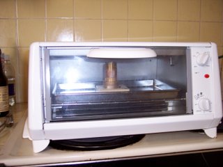
It took only a few moments for the caprolactone to hit 60 degrees and go virtually transparent.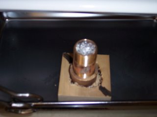
An hour later I locked the extruder barrel in my vise and insertted the poplar piston.
As I expected I had to apply a considerable amount of pressure to get an extrusion going. I got about a metre of good filament out before the extruder barrel extruded to a point where there was more pressure required than I could apply to the piston.
I let the filament hang free and it stretched a bit as a result. If I corrected for the stretch I suspect that I got about 750 mm of 3 mm filament. The quality and shape was excellent. It was the same colour as the granules, had a round cross-section and coiled quite easily.
One bubble about 50 mm into the extrusion exercise was serious enough to cause a structural break in the filament. Other bubbles were so small that they popped and the filament healed. This same phenomena was observed in experiments with the auger extruder done some months ago.
I did a second extrusion and quenched it in water. I got another metre yield with a lot less gravity stretching. Diameter varied between 2.75 and 3.05 mm.
My son was watching the extrusion and noticed something of good interest. He noted that bubbles were happening when I let off pressure on the piston for a moment and the extruder drew air into the cylinder through the extruder orifice.
Here goes...
Here's a view of the very complex 2.77mm extrusion orifice....
...and the super sophisticated method for avoiding dribble during the heating cycle.

...and how I'm going to keep it upright in the toaster oven.
Now we prep to charge the extruder... ...very tricky...

A tablespoon was used for charging the extruder barrel...

Here you can see the famous toaster oven with the extruder inside and the IR thermometer laying on it's door.

And away we go...

It took only a few moments for the caprolactone to hit 60 degrees and go virtually transparent.
An hour later I locked the extruder barrel in my vise and insertted the poplar piston.
As I expected I had to apply a considerable amount of pressure to get an extrusion going. I got about a metre of good filament out before the extruder barrel extruded to a point where there was more pressure required than I could apply to the piston.
I let the filament hang free and it stretched a bit as a result. If I corrected for the stretch I suspect that I got about 750 mm of 3 mm filament. The quality and shape was excellent. It was the same colour as the granules, had a round cross-section and coiled quite easily.
One bubble about 50 mm into the extrusion exercise was serious enough to cause a structural break in the filament. Other bubbles were so small that they popped and the filament healed. This same phenomena was observed in experiments with the auger extruder done some months ago.
I did a second extrusion and quenched it in water. I got another metre yield with a lot less gravity stretching. Diameter varied between 2.75 and 3.05 mm.
My son was watching the extrusion and noticed something of good interest. He noted that bubbles were happening when I let off pressure on the piston for a moment and the extruder drew air into the cylinder through the extruder orifice.
Shopping...
The new PIC programmer is on order and should be here by Thursday or Friday. Randy at Glitchbuster is just over the state line in Nevada right by Lake Tahoe.
In the meantime I put all the Mk II parts in a ziplock and headed down to the hardware supply store.
The M3 bolts aren't readily available in the lengths that Adrian specified, nor is M5 studding.
I was able to match M3 bolts pretty closely with American machine bolts size 10-40 and while 1/4-inch American studding is a bit bigger than M5 (a bit of widening of the cavity will be required) the pitch of the threads is virtually identical (20/inch = 0.79 metric pitch while M5 has 0.8 pitch).
Here's the Americanised Mk II bolted together...
I decided to simply size up my piston extruder concept. I hit the plumbing section of the hardware store and discovered that steel pipe is welded seam and the seams are NASTY, so I went for brass.
I tapped the cap with the same 7/64-inch drill bit that produced 3.15 mm diameter filament in earlier experiments. Interestingly, the cap thickness is no more than 2 mm.
I will be buying a few 16F877A's for running the Mk II so that I don't have to be so clever in measuring things like thermistors and Hall-effect chips.
I'm planning on making a piston out of the ubiquitous poplar and also make a poplar bracing rack for it in the toaster oven with a bamboo plug for the extrusion orifice. This one is a 22 mm diameter x 52 mm. It holds 19.3 cm^3 of polymer which is enough for 2.7 metres of filament which will keep the Mk II going for a bit over 2 hours and 30 minutes at 4 mm/sec.
Basically, you fill it with polymer pellets, pop it in the toaster oven and when it's ready take it out and extrude filament.
This one I plan to run by hand again and, if I get promising results, attach to the Siemens gearmotor to it using the thrust design that Brett put together some months ago.
In the meantime I put all the Mk II parts in a ziplock and headed down to the hardware supply store.
The M3 bolts aren't readily available in the lengths that Adrian specified, nor is M5 studding.
I was able to match M3 bolts pretty closely with American machine bolts size 10-40 and while 1/4-inch American studding is a bit bigger than M5 (a bit of widening of the cavity will be required) the pitch of the threads is virtually identical (20/inch = 0.79 metric pitch while M5 has 0.8 pitch).
Here's the Americanised Mk II bolted together...
I decided to simply size up my piston extruder concept. I hit the plumbing section of the hardware store and discovered that steel pipe is welded seam and the seams are NASTY, so I went for brass.
I tapped the cap with the same 7/64-inch drill bit that produced 3.15 mm diameter filament in earlier experiments. Interestingly, the cap thickness is no more than 2 mm.
I will be buying a few 16F877A's for running the Mk II so that I don't have to be so clever in measuring things like thermistors and Hall-effect chips.

I'm planning on making a piston out of the ubiquitous poplar and also make a poplar bracing rack for it in the toaster oven with a bamboo plug for the extrusion orifice. This one is a 22 mm diameter x 52 mm. It holds 19.3 cm^3 of polymer which is enough for 2.7 metres of filament which will keep the Mk II going for a bit over 2 hours and 30 minutes at 4 mm/sec.
Basically, you fill it with polymer pellets, pop it in the toaster oven and when it's ready take it out and extrude filament.
This one I plan to run by hand again and, if I get promising results, attach to the Siemens gearmotor to it using the thrust design that Brett put together some months ago.
Monday, June 19, 2006
Peristaltic Polyfilla
Zach suggested using a peristaltic pump for room-temperature RepRap extruders. This is nice because it should be very easy to make one using rapid prototyping. But I thought that a problem might be that the flow would be too pulsed.
Time for an experiment:

I stole an old peristaltic pump (temporarily) from colleagues in Biology & Biochemistry, filled a syringe with the same Polyfilla that James used for his experiments, and set it running. Here's a (slightly out-of-focus) close-up:
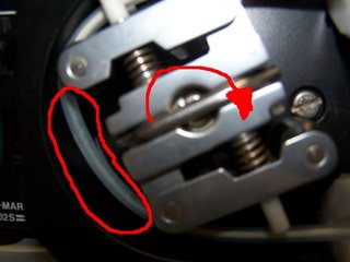
The direction of rotation was as the red arrow indicates, and you can see a void behind the roller ringed in red. The suction created caused some of the liquid in the Polyfilla to vapourise. Unsurprisingly, the stream out was very intermittent.
Then I put a pressure on the syringe (in a real design, this could easily be done with a weight):
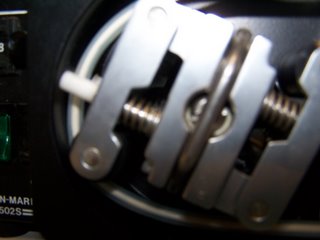
The result was a smooth flow with no interruptions. The soft tube did tend to drift round the pump in the direction of rotation, but in a real design it should be easy to anchor.
So. Off to design an RP peristaltic pump...
Saturday, June 17, 2006
Heresy?
If you scrape away all the idealism what we seem to be doing here is as simple as making a CNC positioning system that mounts a polymer extusion tool instead of a more conventional tool head.
We have a brilliant design for a room temperature polymer extruder. It wants to use filament which is not a terrifically difficult technical problem to solve. The rest of the stuff that we're doing is, when you get right down to it, nothing more than the same problems that the rest of the hobby CNC community are addressing every day in a million different ways.
Cool! :-D
How did I get here? A few days ago one of the people who occasionally comments on what we do on this blog noted that what he sees CDC machines doing most often is making parts for for other CNC machines. That thought has been rooting around in my mind like a kanker ever since.
Shortly after that in responding to a comment on one of my blog postings I did a recap of a quick quantity survey on the poplar that had been used in Godzilla. What jumped out at me is that if I had a proper workshop I could have made it out of rough poplar that cost maybe US$30 rather than the milled, expensive pieces costing maybe US$100-150 that I bought that suited my hand saw and mitre box.
What didn't hit me until this morning is that if I mount my Dremel tool with a cutting head on it on Godzilla instead of a Mk II extruder... I have a proper workshop...
Letting the other shoe drop the natural question arises that if you can replicate the structure of Godzilla out of U$30 of poplar why should you want to insist on doing it instead with maybe US$75 worth of caprolactone?
I think the melts I did in my toaster oven started me thinking in this direction. It is a simple matter to melt HDPE into quite a respectable ingot (this is even easier to do with caprolactone) whereas making the same HDPE into filament that will run in something like a Mk II is a lot more trouble. Why not mill the ingot into what you want and save the swarf instead of making everything into filament and trying to extrude everything.
Similarly, Simon, if I recall correctly, was talking about setting up a furnace capable of melting aluminum. Those aren't hard to make. Why not use aluminum in a RepRap? You can make a cupola furnace that will melt steel into ingots for not a lot more. Why not use steel in a RepRap?
After all, we do already anyway, don't we?
If you think of a RepRap as a CNC machine that has a bunch of tool heads, an extruder being only one of many, the whole concept gets a lot more flexible and interesting to me. :-)
Testing assumptions about polymer melts...
The first assumption that I tested vis a vis the proposed filament method was whether I could melt polymer bits in a pot.
The short answer is that you can, if you put the pot in an oven where it gets heated evenly. The leftmost sample is caprolactone whilst the right is HDPE. The HDPE sample was brownish because the bits used in the melt were cut with a rusty saw. It makes for a nice marbled appearance. The caprolactone was heated for 30 minutes at 130 degrees Celsius while the HDPE was also heated for 30 minutes but at 160 degrees.
The corelle ware cup at the top right was the crucible for the melts. Corelle ware has the advantage that plastics no not adhere to it.
While I was at Santa Barbara yesterday and today I asked myself whether if you simply powered a capillary viscometer instead of putting a weighted piston on top of the polymer melt if you couldn't efficiently make filament.
The numbers seem to work. A polymer melt can easily be done in a cylinder with internal dimensions of 50 mm diameter x 100 mm height. That much melt, converted to filament, would let the Mk II operate for about 70 hours at 4 mm/sec.
I am going to go look at plumbing and piping parts this weekend and cobble something together. :-)
Friday, June 16, 2006
Vik doing Reprap when he should be resting his back...

This is a test hexagon done with Adrians new CSG code. Ash (who is typing this) and Vik used a 0.8mm nozzle at 140C to print this
20mm x 5mm hexagon. There is an interesting and consistent defect which the keen student may wish to analyse.

We believe this is caused by the nozzle trailing its contents out as it hovers around the workpiece while its not meant to be printing. It takes a while to fill the nozzle and the gap between the nozzle and the workpiece. During this time the head currently moves. Perhaps it shouldn't.
Ash
(with Vik hovering over his shoulder)
Thursday, June 15, 2006
First crude attempts at calibration...
I've been worried that the unpowered side of the z-axis platform might be lagging behind the powered side, creating a wag. I tried measuring this yesterday by marking one the near edge of both y-axis towers on their guide bar and do it when the z-axis moves out and marking it again when it came back. The wag should have been half of the difference between the gap on the unpowered side minus the gap on the powered side.
That exercise seemed to show about a 1.2 mm wag. I tightened the z-axis cables after that and the wag seemed to have gone away.
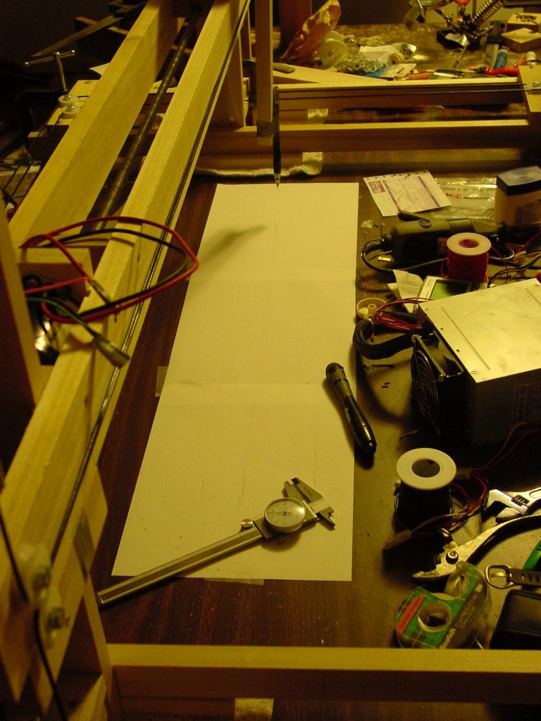
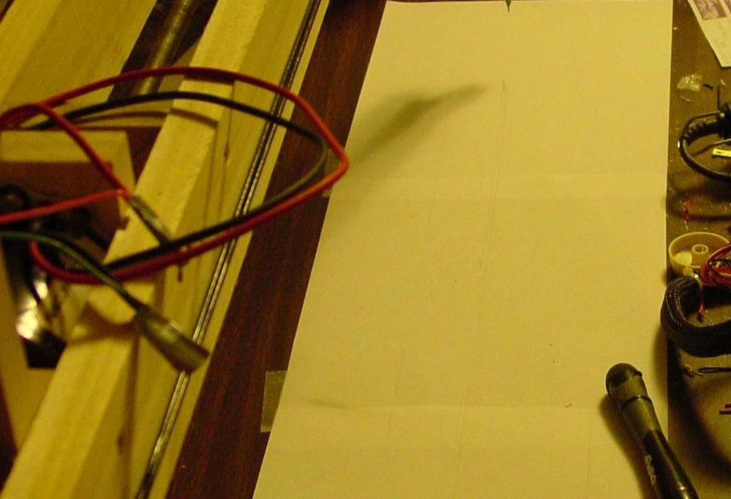
This evening I decided to take a more direct approach, so I just taped down several sheets of typing paper and taped a mechanical pencil to the x-axis platform. I then drew a line from the powered side to the unpowered side when the z-axis platform had been moving out and again when I moved it back, capturing both sides of the wag. I then used my calipers to measure the distance between the lines at either end to calculate the wag.
The wag seemed to be less than the 0.5 mm width of the pencil line, which is to say, unmeasureable.
I had the idea today that if I put limits switches on both sides of the z-axis platform that ought, along with information from the rotary encoder, to be enough data to develop correction coefficients for the z-axis.
I also disassembled the z-axis to see how much play was in the coupling nut. Interestingly, there is very little if any play along the axis of of the threaded rod. The nut can, however, be rattled in position on the threaded rod slightly. It's not an antibacklash fitting, but it's not bad.
One thing that I did spot is that I have a bit of vibration in the x-axis platform. The mechanical pencil faithfully recorded it like my very own little seismograph. The amplitude of the vibration was about 0.64 mm. I am going to have to smooth out the action of the x-axis platform a bit. That shouldn't be too difficult.
I ran a similar test with the z-axis looking for vibration. There was no visible vibration in the z-axis translation.
UPDATE ON X-AXIS VIBRATION: A little block of PTFE taped onto the vertical pencil mounting block serving as a guide on the x-axis side bar got rid of about 90% of the vibration at the mechanical pencil point. It will be very easy to sort out.
That exercise seemed to show about a 1.2 mm wag. I tightened the z-axis cables after that and the wag seemed to have gone away.
This evening I decided to take a more direct approach, so I just taped down several sheets of typing paper and taped a mechanical pencil to the x-axis platform. I then drew a line from the powered side to the unpowered side when the z-axis platform had been moving out and again when I moved it back, capturing both sides of the wag. I then used my calipers to measure the distance between the lines at either end to calculate the wag.
The wag seemed to be less than the 0.5 mm width of the pencil line, which is to say, unmeasureable.
I had the idea today that if I put limits switches on both sides of the z-axis platform that ought, along with information from the rotary encoder, to be enough data to develop correction coefficients for the z-axis.
I also disassembled the z-axis to see how much play was in the coupling nut. Interestingly, there is very little if any play along the axis of of the threaded rod. The nut can, however, be rattled in position on the threaded rod slightly. It's not an antibacklash fitting, but it's not bad.
One thing that I did spot is that I have a bit of vibration in the x-axis platform. The mechanical pencil faithfully recorded it like my very own little seismograph. The amplitude of the vibration was about 0.64 mm.
 I am going to have to smooth out the action of the x-axis platform a bit. That shouldn't be too difficult.
I ran a similar test with the z-axis looking for vibration. There was no visible vibration in the z-axis translation.
UPDATE ON X-AXIS VIBRATION: A little block of PTFE taped onto the vertical pencil mounting block serving as a guide on the x-axis side bar got rid of about 90% of the vibration at the mechanical pencil point. It will be very easy to sort out.
Wednesday, June 14, 2006
Thinking about making filament again...
Okay, I have a couple of days till the PIC's arrive and Vik brought up the point of there being a developing need for filament production, so I've been thinking about it enough the I want to throw out what may be an approach for you all.
As you know, I was very excited about and did a lot of work on an auger extruder for filament. I got unexcited instantly when I found out how much better filament a simple piston design did the job.
The auger design I did requires powdered polymer unless you go up to the sort of auger diameters that Adrian used. As well, the auger design that I did wanted being broken down and cleaned practically every time you used it if you wanted good results. It also had problems with bridging of polymer powder jamming the feed hopper and any number of other maladies. It was basically German design, attractive but complicated and requiring rather careful use when what we need is Russian design, primitive, ugly and utterly reliable.
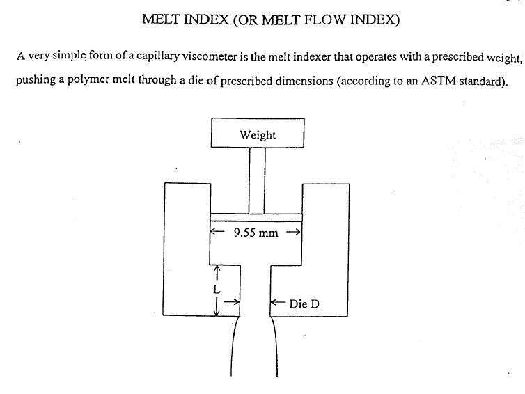
What I was using looked very much like a standard ASTM standard test rig for determining polymer melt index.
I got the illustration from a lab manual used up at McMaster University. You can see the full document here.
http://chemeng.mcmaster.ca/courses/che4l2/labmodules/polymer.pdf
It's a nice concept except that it's a one shot device and looks to be a pig to use on a production basis if the user's manual is any guide.
Adrian was talking about using a pressure cooker some time ago and I had thought along the same lines as well. Taking the bare essentials from that idea, what would happen if we just tossed our scrap CAPA in a pot and heated it. Don't get lost in the details of how to heat the pot just yet, just assume that we can do it without scorching.... use a double boiler or something. :-)
Okay, so we've got this heated pot of scrap polymer. After a while the bits melt into a big puddle, the polymer slumps down (very slowly given its viscosity) . Now suppose we've drilled a hole in the side of the pot way down at the bottom well under the level of the molten polymer.
Then we start plumbing up a two stroke pump using Adrian's favourite plumbing parts. :-)
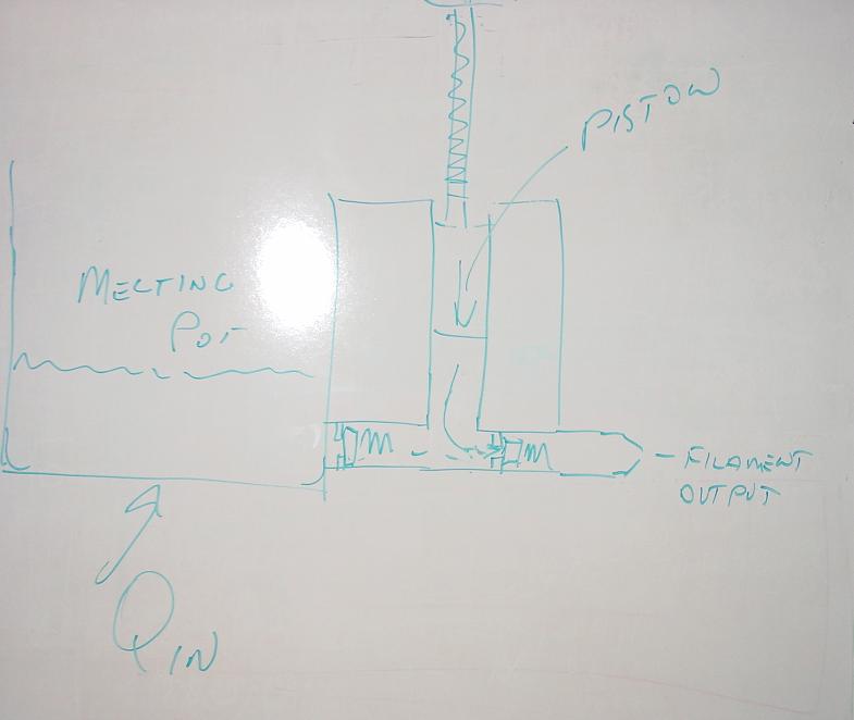
Here's roughly what the intake stroke looks like...
Pardon the illustration. I drew it on my white board and photographed it. That's not a great presentation method, but I'm in a hurry.
Your pot's on the left and the piston of your pump is driven by a gear motor that runs a threaded rod arrangement. I didn't get too specific on how that all fits together. At this point what is relevant is that we have what amounts to a linear motor that can deliver a LOT of thrust.
You can see two spring loaded back pressure valves. On the intake stroke the valve to the pot opens up letting the polymer melt be drawn in as the piston is pulled upwards in the cylinder.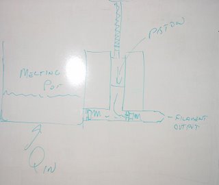
Once your cylinder is full you reverse the rotation of the gear motor which closes the back pressure valve into the pot and opens the valve to the extruder tip.
That's basically it.
What's nice is that this system can operate VERY slowly to take into account the high viscosity of the polymer melt. It can also extrude specific amounts of polymer with a high degree of accuracy. Knowing the mass flow rate of polymer out of the extruder on a real-time basis lets us control a conveyer that takes the extruded polymer away.
That's my first cut at a filament extruder.
As you know, I was very excited about and did a lot of work on an auger extruder for filament. I got unexcited instantly when I found out how much better filament a simple piston design did the job.
The auger design I did requires powdered polymer unless you go up to the sort of auger diameters that Adrian used. As well, the auger design that I did wanted being broken down and cleaned practically every time you used it if you wanted good results. It also had problems with bridging of polymer powder jamming the feed hopper and any number of other maladies. It was basically German design, attractive but complicated and requiring rather careful use when what we need is Russian design, primitive, ugly and utterly reliable.
What I was using looked very much like a standard ASTM standard test rig for determining polymer melt index.
I got the illustration from a lab manual used up at McMaster University. You can see the full document here.
http://chemeng.mcmaster.ca/courses/che4l2/labmodules/polymer.pdf
It's a nice concept except that it's a one shot device and looks to be a pig to use on a production basis if the user's manual is any guide.
Adrian was talking about using a pressure cooker some time ago and I had thought along the same lines as well. Taking the bare essentials from that idea, what would happen if we just tossed our scrap CAPA in a pot and heated it. Don't get lost in the details of how to heat the pot just yet, just assume that we can do it without scorching.... use a double boiler or something. :-)
Okay, so we've got this heated pot of scrap polymer. After a while the bits melt into a big puddle, the polymer slumps down (very slowly given its viscosity) . Now suppose we've drilled a hole in the side of the pot way down at the bottom well under the level of the molten polymer.
Then we start plumbing up a two stroke pump using Adrian's favourite plumbing parts. :-)
Here's roughly what the intake stroke looks like...

Pardon the illustration. I drew it on my white board and photographed it. That's not a great presentation method, but I'm in a hurry.
Your pot's on the left and the piston of your pump is driven by a gear motor that runs a threaded rod arrangement. I didn't get too specific on how that all fits together. At this point what is relevant is that we have what amounts to a linear motor that can deliver a LOT of thrust.
You can see two spring loaded back pressure valves. On the intake stroke the valve to the pot opens up letting the polymer melt be drawn in as the piston is pulled upwards in the cylinder.
Once your cylinder is full you reverse the rotation of the gear motor which closes the back pressure valve into the pot and opens the valve to the extruder tip.
That's basically it.
What's nice is that this system can operate VERY slowly to take into account the high viscosity of the polymer melt. It can also extrude specific amounts of polymer with a high degree of accuracy. Knowing the mass flow rate of polymer out of the extruder on a real-time basis lets us control a conveyer that takes the extruded polymer away.
That's my first cut at a filament extruder.
- It can deal with either scrap polymer or virgin resin.
- It is highly controllable and information rich thereby
- It can largely be made of plumbing parts if we wish
Fine tuning Godzilla...
As parts have worn in Godzilla is translating more and more smoothly. The big plus is that the Frankenmotors draw much less current now, I'm suspecting less than 4 amps on the basis that the motor housings no longer warm more than a very few degrees over air temperature.
I had a clatter and some bumpy movement in the powered y-axis tower. Today I broke it down and discovered that the coupling nut in the thrust collar was a bit lose in its housing and slipping occasionally, which was what was causing the clatter. Wrapping the coupling nut in a bit of duct tape smoothed that right out.
The translation of the extruder platform on the x-axis has smoothed out but oddly still doesn't go any faster than it did before.
Duct tape has proved more than adequate to connect the Frankenmotors and the threaded drive shafts.
It took a while to get the balance between cable tension in the force transfer system between the two z-axis modules and added load on the Frankenmotor driving the stage. When I first set the z-axis stage cabling up I was getting about 0.7 mm of wag between the powered and cable-driven halves of the stage. I wasn't particularly worried about that in that the wag was very predictable and could have been numerically accounted for in a calibration routine. Today, however, now that the z-axis has worn in I was able to safely increase the cable tension until the wag between modules was too small to measure with my calipers. Having no detectable wag makes life considerably easier.
Tuesday, June 13, 2006
First Complete Object & Tower of Ooze
Using card stuck to glass as a deposition base in Da Witch, I managed to persuade the RepRap to output a full 5mm thick sample hexagon - solid yet, without gaps - with no manual intervention whatsoever. It's a bit rough but I'm pretty pleased about it, and here's the photo to prove it:

The stuff on the left is the "Tower of Ooze" that is created as the nozzle, conveniently moved over this spot for the purpose, dribbles as it warms up. The tower sticks well to the card, solving the problem of using glass whereby the Tower of Ooze elopes with the hot print head and runs off across the deposition surface. Adhering to the card also stops the workpiece curling up like an old sandwich.
Vik :v)
Sunday, June 11, 2006
Frankenmotors running all three axes on Godzilla...
I got the little x-axis platform that will carry the Mk II extruder built this morning. 
The x-axis is translating at about 28 mm/sec right now. I expect that that velocity will pick up substantially as the drive collar coupling nut and the threaded drive rod wear in a bit.
With the z-axis translating at 32 mm/sec and the x-axis moving at 28 Godzilla has a maximum extrusion speed of about 42-43 mm/sec right now. That's using 12v.
I ran the test over again using 5.45v and got the z-axis moving reliably at 10 mm/sec and the x-axis moving at 7 mm/sec. Hah! I may be able to start working at improving the MK II even before I get the axes' speed controller boards finished. :-D
Here are a couple of videos of the z and x axis running at the same time.
Short clip
Longer, more uncoordinated clip
Slicing and Dicing
The code to take horizontal slices through STL files is coming along.
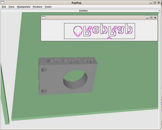
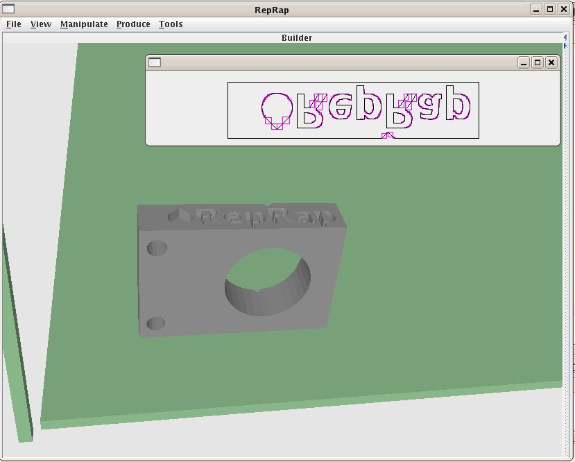
The picture shows the RepRap GUI with an STL file loaded (this is clearly a silly orientation in which to build this block-like object, but it lets me slice the logo...). Inset is the cross-section generated near the top of the block when the "Produce" button is pressed (the purple rectangles can be ignored - they're for debugging).
At the moment the information is an unstructured list of line segments. Now to add some structure so the extruder can follow it...
Godzilla y-axis meets the Frankenmotor...
I was going to get up in the morning and hook up the Frankenmotor to the y-axis tower. About 2130, however, I decided what the hell the night is young.
There was quite a bit of drama. The coupling nut that I am using as the basis of my thrust collar was rather tight on the drive shaft and tended to seize up. I ran it by itself for a while till the jagged chunks wore off and then greased the threaded drive rod and exercised the coupling nut by itself some more.
Then it turned out that the wooden collar that I'd built was too tight as well. I replaced one of the brass screws, something I'll never use again since the darned things tend to strip their heads on my Phillips head screwdriver (What DO Brits call a cross profile screwdriver, anyway? I used to know. For the Swedes it was a kryssskruvmejsel which was straightforward enough.) . Americans tend to name tools after the first company that made a particular tool.... Skill Saw, Phillips head screwdriver, Crescent wrench (adjustable spanner), and etc.
Here's a videoclip of the Godzilla y-axis plus Frankenmotor in action.
The y-axis motion was a little jumpy, though that smoothed out the more I ran it. Note the brass flathead screw that I've balanced upright on its head on the x-axis Frankenmotor mounting block in the video clip. We've got some vibration for right now in the Y-axis translation, but not much as you can see because the screw is happy to remain upright. :-)
Godzilla y-axis towers strung up!
The y-axis (vertical) towers are now operating on one motor thanks to Ed and his excursion into cabling. :-)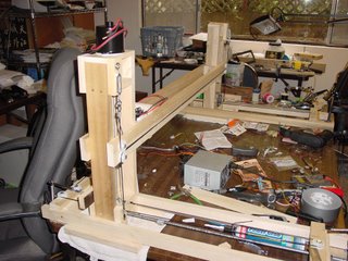
All it is is a huge 3D parallel bar of the sort you used to find attached to rooms full of drafting tables in any engineering or architecture school on the planet.
The parallel bar always had a little plastic cover over it so that you wouldn't get your fingers or tie tangled in the cable crossing in the middle.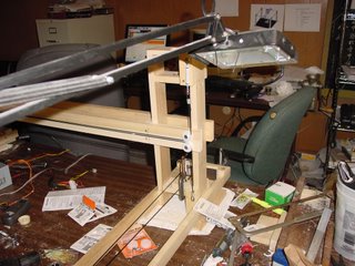
It's idiotically simple. Just my style! :-D
Just like a parallel bar you can raise or lower the whole x-axis bridge with a two fingers. When I rig the other side of the x-axis bridge I suspect that you will be able to use one finger. You can see that white bar of PTFE that I have supporting it over on the drive (left) side of Godzilla. There's not enough friction in the rig to keep in in place. No big deal.
You gave up too soon on cabling, Ed! It works great, you just have to keep it simple. :-)
I installed the cabling and pulleys on the back side and I can indeed now lift it with one finger.
Of course, I can also straight arm 50 lb bags of horse cubes with left hand, too, so maybe that doesn't mean a whole lot. I learned that little trick 5-6 years ago when I broke my right forearm in 8 pieces and all the same had to look after a hungry appaloosa who didn't want to hear about sick and looking after his own breakfast and sanitary arrangements. Fortunately, the hardware that they screwed all the bits too was pretty much non-ferrous and doesn't set off airport metal alarms.
In any case, the x-axis bridge is balanced much more evenly now. The additional cabling put a little more resistance in the system so that when I let go of it it descends slowly by itself. I expect that once I hook up the thrust collar on the threaded drive rod it will stay put at whatever level I decide to park it at.
Motors in the morning and maybe a design charrette on that piston driven filament extruder that Vik has developed a hankering for till the new PICs and parts come in. :-)

All it is is a huge 3D parallel bar of the sort you used to find attached to rooms full of drafting tables in any engineering or architecture school on the planet.

The parallel bar always had a little plastic cover over it so that you wouldn't get your fingers or tie tangled in the cable crossing in the middle.
It's idiotically simple. Just my style! :-D
Just like a parallel bar you can raise or lower the whole x-axis bridge with a two fingers. When I rig the other side of the x-axis bridge I suspect that you will be able to use one finger. You can see that white bar of PTFE that I have supporting it over on the drive (left) side of Godzilla. There's not enough friction in the rig to keep in in place. No big deal.
You gave up too soon on cabling, Ed! It works great, you just have to keep it simple. :-)
I installed the cabling and pulleys on the back side and I can indeed now lift it with one finger.
Of course, I can also straight arm 50 lb bags of horse cubes with left hand, too, so maybe that doesn't mean a whole lot. I learned that little trick 5-6 years ago when I broke my right forearm in 8 pieces and all the same had to look after a hungry appaloosa who didn't want to hear about sick and looking after his own breakfast and sanitary arrangements. Fortunately, the hardware that they screwed all the bits too was pretty much non-ferrous and doesn't set off airport metal alarms.
In any case, the x-axis bridge is balanced much more evenly now. The additional cabling put a little more resistance in the system so that when I let go of it it descends slowly by itself. I expect that once I hook up the thrust collar on the threaded drive rod it will stay put at whatever level I decide to park it at.
Motors in the morning and maybe a design charrette on that piston driven filament extruder that Vik has developed a hankering for till the new PICs and parts come in. :-)
Saturday, June 10, 2006
And the second string does exhibition during timeout...
I was down to two working PIC chips and didn't want to waste the weekend, so I went back to working on the cabling for Godzilla.
The biggest job was getting a Frankenmotor installed in the x-axis ensemble. I had to excavate a considerable cavity in both side supports with a chisel to get it to fit. The real pig of a job, however, was getting the motor shaft aligned with the threaded drive shaft.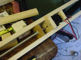
I got it done, but it took most of the morning, very fiddly stuff.
Adrian wanted to see the two y-axsis towers with the x-axis ensemble on board. Here it is.

For good measure here are two short video clips of it running as an ensemble.
Drive side video clip
Far side video clip
I was playing music this morning during the tests which sounded considerably better than the deranged chimpanzee on the jack hammer noise of the motors by themselves. That loud snapping in the first clip is me switching the toggle switch. It gives you some idea of how sensitive the camera microphone is.
If you like the music it was done by a jam session consisting of part of a musical group called Spælimenninir i Hoydølum (lit. Players/Musicians in Hoydølum) in the Faroe Islands plus Angelika Nielsen, Jakup Lützen and another very young woman violinist whose name I do not know.
I was listening to a series of their performances at some sort of folk festival at Gøta. You can find the clips at a favourite little folk music website of mine which originates out of Scandinavia.
If you go there and click on the Faroe Islands buttons you can listen to Spælimenninir. Angelika Nielsen, the big blonde violinist on the clips, also has a solo piece on the same links page. She's a dead ringer for my ex-wife (though she's maybe 15-25 years younger than my ex is now) whose family hailed from that same neck of the woods (Shetlands and Orkneys) maybe 180 years ago. It must have been a tiny little gene pool. Mind, I suspect I would still have my ex-wife if she had been that musically talented. I love that kind of music. :-D
You know, though, I wonder at times whether listening to that sort of music keeps the shadows at bay or simply beckons them closer like a warm campfire on a cold evening. :-)
The biggest job was getting a Frankenmotor installed in the x-axis ensemble. I had to excavate a considerable cavity in both side supports with a chisel to get it to fit. The real pig of a job, however, was getting the motor shaft aligned with the threaded drive shaft.

I got it done, but it took most of the morning, very fiddly stuff.
Adrian wanted to see the two y-axsis towers with the x-axis ensemble on board. Here it is.
For good measure here are two short video clips of it running as an ensemble.
Drive side video clip
Far side video clip
I was playing music this morning during the tests which sounded considerably better than the deranged chimpanzee on the jack hammer noise of the motors by themselves. That loud snapping in the first clip is me switching the toggle switch. It gives you some idea of how sensitive the camera microphone is.
If you like the music it was done by a jam session consisting of part of a musical group called Spælimenninir i Hoydølum (lit. Players/Musicians in Hoydølum) in the Faroe Islands plus Angelika Nielsen, Jakup Lützen and another very young woman violinist whose name I do not know.
I was listening to a series of their performances at some sort of folk festival at Gøta. You can find the clips at a favourite little folk music website of mine which originates out of Scandinavia.
If you go there and click on the Faroe Islands buttons you can listen to Spælimenninir. Angelika Nielsen, the big blonde violinist on the clips, also has a solo piece on the same links page. She's a dead ringer for my ex-wife (though she's maybe 15-25 years younger than my ex is now) whose family hailed from that same neck of the woods (Shetlands and Orkneys) maybe 180 years ago. It must have been a tiny little gene pool. Mind, I suspect I would still have my ex-wife if she had been that musically talented. I love that kind of music. :-D
You know, though, I wonder at times whether listening to that sort of music keeps the shadows at bay or simply beckons them closer like a warm campfire on a cold evening. :-)
Video of Da Witch in action
There have been a few requests for some video, so here's a 2.7MB straight MPEG, about 24s showing the deposition process in action on the Da Witch prototype. This is a still taken from the video and the object being deposited:


The hexagon is being deposited with a 0.8mm nozzle running at 140C driven by the latest GUI. The mess on the left of the new glass deposition surface is where the nozzle moves to dribble when it reheats. The glass is held snugly on the stage by cunningly-shaped self-adhesive foam strips.
Here's a shot in close-up of the plastic still hot and transparent, exuding from the nozzle in the second layer of a cross-hatch pattern:

So far the most complete layers we've deposited is 4, but this has been done a few times now and is no longer an unusual or particularly tricky event. Now it is repeatable, experimentation to find the best nozzle can begin changing one factor at a time. That's science :)
Vik :v)
The hexagon is being deposited with a 0.8mm nozzle running at 140C driven by the latest GUI. The mess on the left of the new glass deposition surface is where the nozzle moves to dribble when it reheats. The glass is held snugly on the stage by cunningly-shaped self-adhesive foam strips.
Here's a shot in close-up of the plastic still hot and transparent, exuding from the nozzle in the second layer of a cross-hatch pattern:
So far the most complete layers we've deposited is 4, but this has been done a few times now and is no longer an unusual or particularly tricky event. Now it is repeatable, experimentation to find the best nozzle can begin changing one factor at a time. That's science :)
Vik :v)
Thursday, June 08, 2006
PWMing along...
Got the little yellow G4 gear motor going on the test board. I wore out two PIC16F628A chips learning how which is cheap at the price. :-)
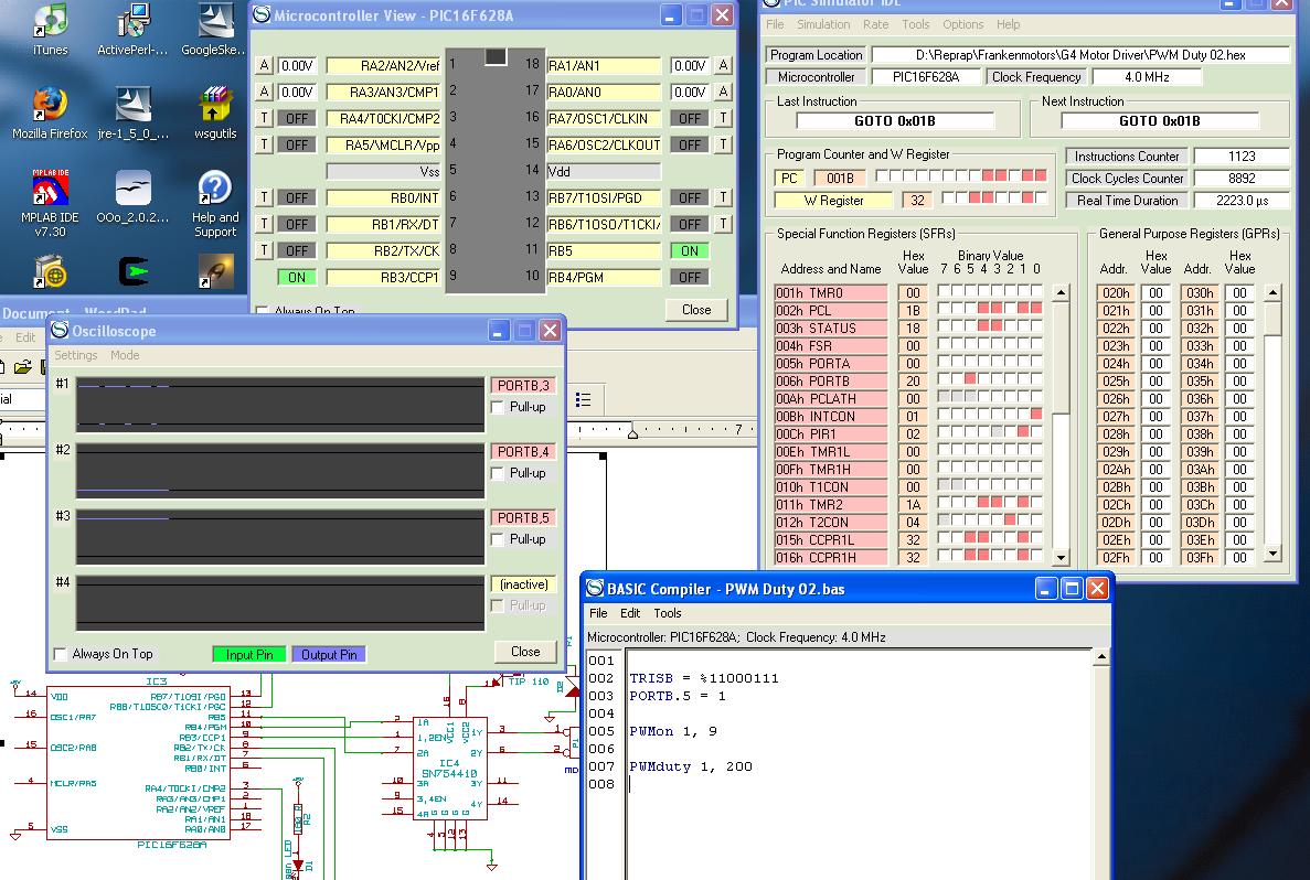
Here's the little test programme in BASIC that does the job...
TRISB = %11000111
PORTB.5 = 1
PWMon 1, 9
PWMduty 1, 200
That's it. The TRISB and PORTB settings I got out of Adrian's servo.c code. Works like a champ.
Things started moving really fast after I figured out how to connect the virtual oscilloscope to the virtual PIC16F628A chip. I've also got a virtual signal generator which should let the retarded Plaas integrate the rotary encoder chip and limits switches when I get my nerve up to try that. :-s
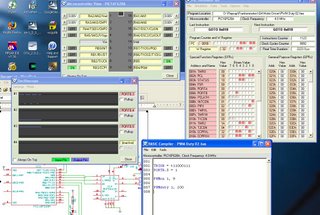
Here's a pic of the IDE in action.
YES!!!!!!!
Here's the little test programme in BASIC that does the job...
TRISB = %11000111
PORTB.5 = 1
PWMon 1, 9
PWMduty 1, 200
That's it. The TRISB and PORTB settings I got out of Adrian's servo.c code. Works like a champ.
Things started moving really fast after I figured out how to connect the virtual oscilloscope to the virtual PIC16F628A chip. I've also got a virtual signal generator which should let the retarded Plaas integrate the rotary encoder chip and limits switches when I get my nerve up to try that. :-s
Here's a pic of the IDE in action.
YES!!!!!!!
Wednesday, June 07, 2006
G4 Motor Control Card
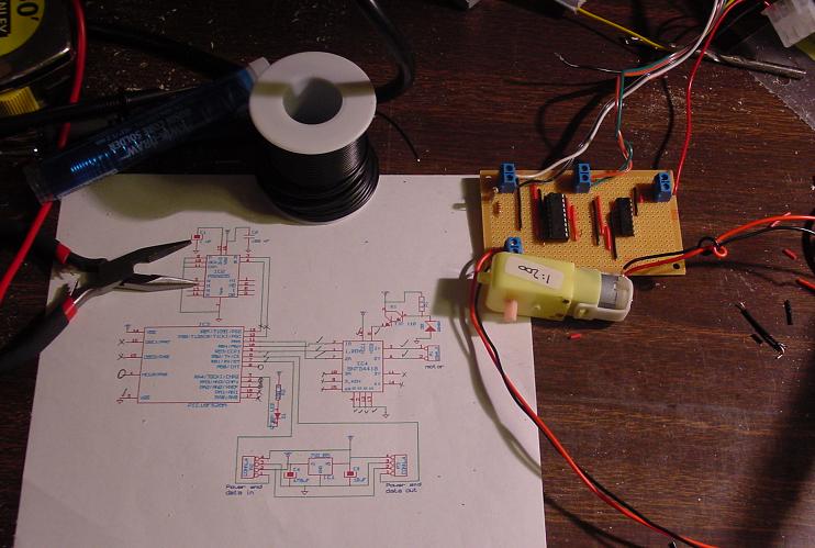
The Oshon Basic compiler made establishing serial comms with the PIC16F628A UART pretty much child's play. Adrian's schematic for controlling a G4/rotary encoder ensemble was pretty clear, so I decided that my next baby step would be to see if I could just control a G4 from my PC via serial comms via our standard PIC. I trimmed down Adrian's schematic to the bare essentials and built up a test board. 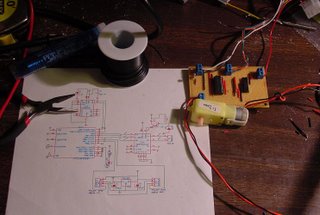
I was then able to leverage the UART programme that I knew already worked to test the board and got it going on the third try after breaking a strip that I'd missed with my Dremel tool and soldering a dry joint that I'd also missed.
It's one thing to just echo characters back to your PC and quite another to send the PIC some information and have it recognise what it is and to know when it has it all and then to tell you that it has it.
That took a bit of hacking at the VB.NET serial comms programme and well as the PIC programme, but with the Oshon PIC Simulator it went fairly smoothly. Now that I have the PIC getting motor speed information from the PC the next step is to port Adrian's PWM routine into the PIC programme and see if I can crank the motor. :-)
Monday, June 05, 2006
Basically PIC...
The Oshon Software PIC Simulator IDE system appears to be an effective, affordable way to work with the PIC16F628A.
I'd previously built up several test boards for the PIC and was trying to crack the serial comms/UART problem.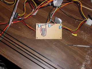 The BoostBasic compiler I tried sorta/kinda worked but Assembler worked a lot better but still had some troubling sorts of behaviours.
It took me 5 minutes to retarget some UART code written in Oshon PIC Basic from the PIC16F877 to the PIC 16F628A, compile it, burn it onto the PIC and get it running first with Hyperterminal and then with the little VB.NET serial comms programme that I'd adapted to talk through the RepRap comms board to my PIC test board.
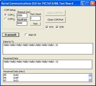
An hour later I rewrote the UART sample code to do a proper job of echoing. That took another big 5 minutes to go from writing to testing the reprogrammed PIC.
My next project will be to build up a little PIC test board with a SN754410 and program it to do speed control with a PWM routine that can be controlled through my serial comms programme. Oshon has a very nice little software emulator for PIC chips that takes your hex file, lets you execute it in software and keep track of what all the ports and registers are doing. I ran it with my UART programme and was able to keep track of the serial IO that I put into the chip and watched it come back out, all before I tried to burn it onto a chip.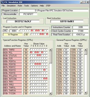 I'm hoping to have time in the next week to get used to running that well enough to make sure that what I think is happening with PWM is really happening. :-)
After that it's integrating the AustriaMicrosystems shaft encoder chip and after that integrating the Hamamatsu optical detector chips for limits control.
Then comes the hard part. I've either got to find a much higher amperage equivalent of the SN754410 or I've got to build one up from components. I have several good schematics for that sort of thing, but the circuits I have will have to be added to for directional control. Hopefully, Freescale has some driver chips that do all that. Their catalog descriptions look hopeful. :-)
I'd previously built up several test boards for the PIC and was trying to crack the serial comms/UART problem.
 The BoostBasic compiler I tried sorta/kinda worked but Assembler worked a lot better but still had some troubling sorts of behaviours.
It took me 5 minutes to retarget some UART code written in Oshon PIC Basic from the PIC16F877 to the PIC 16F628A, compile it, burn it onto the PIC and get it running first with Hyperterminal and then with the little VB.NET serial comms programme that I'd adapted to talk through the RepRap comms board to my PIC test board.
An hour later I rewrote the UART sample code to do a proper job of echoing. That took another big 5 minutes to go from writing to testing the reprogrammed PIC.
My next project will be to build up a little PIC test board with a SN754410 and program it to do speed control with a PWM routine that can be controlled through my serial comms programme. Oshon has a very nice little software emulator for PIC chips that takes your hex file, lets you execute it in software and keep track of what all the ports and registers are doing. I ran it with my UART programme and was able to keep track of the serial IO that I put into the chip and watched it come back out, all before I tried to burn it onto a chip.
 I'm hoping to have time in the next week to get used to running that well enough to make sure that what I think is happening with PWM is really happening. :-)
After that it's integrating the AustriaMicrosystems shaft encoder chip and after that integrating the Hamamatsu optical detector chips for limits control.
Then comes the hard part. I've either got to find a much higher amperage equivalent of the SN754410 or I've got to build one up from components. I have several good schematics for that sort of thing, but the circuits I have will have to be added to for directional control. Hopefully, Freescale has some driver chips that do all that. Their catalog descriptions look hopeful. :-)
Sunday, June 04, 2006
Quick work with the 0.8mm nozzle
I'm getting quite handy at making detatchable nozzles, and this 0.8mm one is I think the least imperfect yet.
The almost 45 degree taper ensures that it doesn't stick much to the substrate, and thus smear everything. Inside, I reamed out right up to the point with one of those reamer bits for a Dremmel tool that look like a little lemon squeezer. The point poked through the hole. Consequently, the flow rate is very high, and it hasn't jammed up the drive mechanism yet. I'm actually running it at less power than the 0.5mm nozzle:

I've left the crosshatch pattern slightly wide, so I can measure the widths of the deposition. For the record, the lines are 1.1mm wide, and each of the two layers are roughly 0.55mm thick - the huge blobs are where the machine pauses to reheat the nozzle and all the plastic runs out. The crosshatch generator believes the lines to be 1.3mm wide. If I slow the motor down much more the lines will get thinner but I think it'll stall. We'll see.
I used about 0.6 metres of CAPA/Polymorph feedstock today! Best make more.
Vik :v)
The almost 45 degree taper ensures that it doesn't stick much to the substrate, and thus smear everything. Inside, I reamed out right up to the point with one of those reamer bits for a Dremmel tool that look like a little lemon squeezer. The point poked through the hole. Consequently, the flow rate is very high, and it hasn't jammed up the drive mechanism yet. I'm actually running it at less power than the 0.5mm nozzle:
I've left the crosshatch pattern slightly wide, so I can measure the widths of the deposition. For the record, the lines are 1.1mm wide, and each of the two layers are roughly 0.55mm thick - the huge blobs are where the machine pauses to reheat the nozzle and all the plastic runs out. The crosshatch generator believes the lines to be 1.3mm wide. If I slow the motor down much more the lines will get thinner but I think it'll stall. We'll see.
I used about 0.6 metres of CAPA/Polymorph feedstock today! Best make more.
Vik :v)
Making the 0.5mm nozzle work
Prior to each test run I have to go through this ritual of finding out which connection is faulty due to intrusion by felines. After flattening the prongs on a few connectors to make them harder to pull out, I got the whole thing going again this morning, with a 3.5mm hole in the middle of the new PTFE block to cope with badly-mangled feedstock (the threaded extrusion mechanism was distorting it somewhat). Still, I've managed to lay down a closely-filled test article with the 0.5mm nozzle, using the aforementioned strengthened 16mm PTFE insulation block to hold the heater. This one is not going to pop out:

But a number of undesirable changes were needed to make this work. The extrusion speed had to be dropped to around 25% of maximum, with the stage speed needing to be dropped slightly as well (215 out of 255). Attempts to extrude at higher speeds resulted in the 3mm Polymorph/CAPA feedstock getting wrapped around the threaded rod in the Mk2 extruder as shown below. I have modified the design of the poly-holder to prevent this from happening, and Adrian is running one off on the Stratasys.

The extruder mechanism also becomes exceptionally sensitive to feedstock quality under high load. Motor speed becomes uneven at variations of 0.2mm (note the uneven edges of the hexagon above), and joins have to be perfect. I achieve good joins by forcing the melted ends of feedstock into opposite sides of a 3mm hole in a block of PTFE.
A better build of the extruder's threaded rod might help, as will a suggested future addition of a speed controller for the extruder. What would help is if someone could extrude some 3mm feedstock for us. Anyone got a spare plastic injection machine that'll do it ? :)
Simon has changed the code to allow different deposition speeds when depositing on an angle, and also to move down one layer before repositioning the head for the next layer. This should reduce some of the smearing. We also need to move the head to one side while re-heating the extruder, and to deposit a test line before each extrusion to ensure the nozzle is fully-charged.
Any leaks around the removable nozzle are soon exposed at these pressures. I have not yet needed to use PTFE tape to take up the slack, though a silicone 'O' ring or washer cut from tube might be useful. I might drop back to using a 0.8mm nozzle for the next round of tests. 'Course, I'll have to build one first...
Vik :v)
But a number of undesirable changes were needed to make this work. The extrusion speed had to be dropped to around 25% of maximum, with the stage speed needing to be dropped slightly as well (215 out of 255). Attempts to extrude at higher speeds resulted in the 3mm Polymorph/CAPA feedstock getting wrapped around the threaded rod in the Mk2 extruder as shown below. I have modified the design of the poly-holder to prevent this from happening, and Adrian is running one off on the Stratasys.
The extruder mechanism also becomes exceptionally sensitive to feedstock quality under high load. Motor speed becomes uneven at variations of 0.2mm (note the uneven edges of the hexagon above), and joins have to be perfect. I achieve good joins by forcing the melted ends of feedstock into opposite sides of a 3mm hole in a block of PTFE.
A better build of the extruder's threaded rod might help, as will a suggested future addition of a speed controller for the extruder. What would help is if someone could extrude some 3mm feedstock for us. Anyone got a spare plastic injection machine that'll do it ? :)
Simon has changed the code to allow different deposition speeds when depositing on an angle, and also to move down one layer before repositioning the head for the next layer. This should reduce some of the smearing. We also need to move the head to one side while re-heating the extruder, and to deposit a test line before each extrusion to ensure the nozzle is fully-charged.
Any leaks around the removable nozzle are soon exposed at these pressures. I have not yet needed to use PTFE tape to take up the slack, though a silicone 'O' ring or washer cut from tube might be useful. I might drop back to using a 0.8mm nozzle for the next round of tests. 'Course, I'll have to build one first...
Vik :v)
![]()