Wednesday, May 31, 2006
The Plan...
Y-AXIS (vertical)

The y-axis (vertical) cabling is a very standard parallel bar pulley and cable arrangement that you used to see on drafting tables.
The parallel bar in this case is the x-axis (horizontal). This arrangement will be done on both sides of the x-axis beam, front and back.
The vertical cable paths will lie on the same line as the y-axis threaded drive shaft that will move the x-axis beam up and down.
Z-AXIS (horizontal)
The z-axis layout is slightly more complicated, but not greatly.
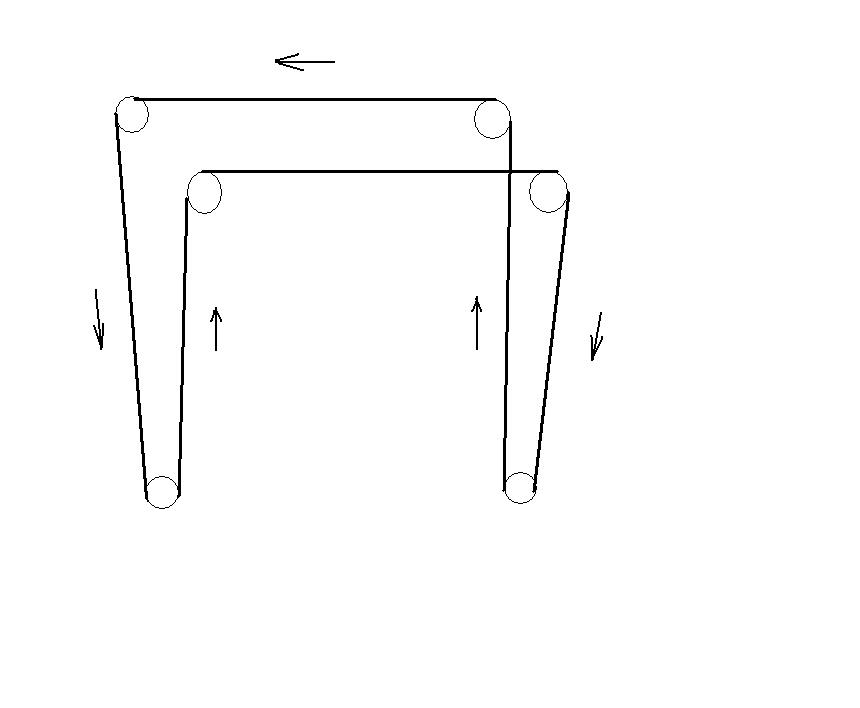
Cable moves from the left z-axis assembly to the right across the top (back) of Godzilla. I've not shown a turnbuckle and spring in this one that I'll be including. The two inner cable tracks with the upward pointing arrows will be attached to the centre-line of the y-axis towers.
Motive power is supplied by the Frankenmotors driving threaded rods on the left hand side of both sketches. It should work. I've got the parts and should know in a few hours, though I may be a bit short of cable and have to do the y-axis towers in the morning, :-)
Plaas catches the cable and pulley disease...
The z-axis is working fine and I'm working on getting the x-axis cranking. I was at the hardware store and saw all the nice little nylon pulleys for curtains....
...then I got to thinking that I'd only bought just enough of the Frankenmotors for Godzilla and I really needed some spares. Being of Scots-Irish ancestry I got to thinking that a cheap way to get spare motors is to not need so many in the design...
...and since the Frankenmotors have enough torque to run 5-6 axes each, never mind one. That, of course, hooked up nicely with the idea that if you only have one motor per axis you don't have to solve the problem of making two motors run in tandem...
...and away I went. Half an hour with my whiteboard and markers and I have a plan.
I LOVE this project! :-D
Monday, May 29, 2006
Frankenmotor meets Godzilla...
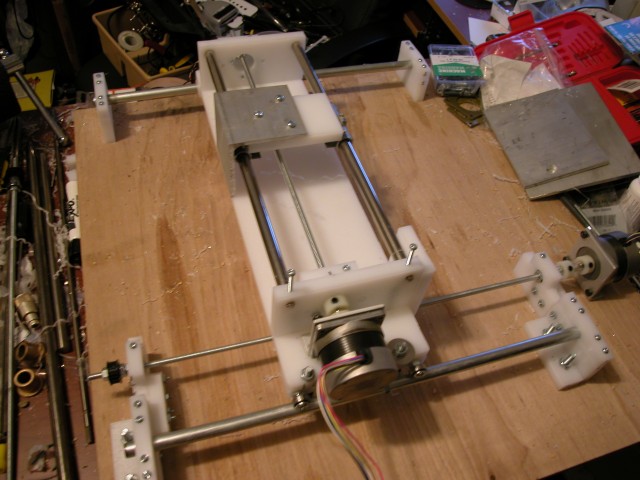
 As you can see the Frankenmotor sets into the Z-axis mounting bulkhead with no problems whatsoever.
 In the second pic you can see my duct tape coupling connecting the motor to the threaded drive rod. Interestingly, I've been running the y-axis tower back and forth for two days now and the coupling is just as good as when I wrapped the joint.
Here is a link to a Quicktime movie of the z-axis doing its 38 mm/sec act.
http://www.sanma12.com/RepRap/z-axis movie.mov
Please take note that the axis in operation is not a hundredth as loud as it sounds like on the movie. My son's camera microphone is adjusted to pick up conversation and rather quiet conversation from a considerable distance at that. The axis in operation comes out sounding like a jackhammer operated by a deranged chimpanzee.
Sunday, May 28, 2006
0.5mm Mk 2 extruder trials/tribulations
So I made a 0.5mm nozzle with a more conical profile. This extrudes a 0.8mm filament, which with care and attention might make a trail narrower than 1mm. Maybe even not too far away from the Stratasys' 0.6mm minimum reliable extrusion width. Interchangeable nozzles continue to be a great idea.
But lo, the pressure generated inside the extrusion mechanism is higher with the smaller nozzle, even when the motor speed is decreased to allow for the reduced throughput. This means that the feed mechanism is now much less tolerant of dodgy feedstock, and I have had a great number of jams with my last batch of somewhat lumpy feedstock.
After a few attempts and unjammings, the entire heater barrel assembly was extruded from the PTFE rod. It just popped out. Now, I'll freely admit that the original tapping of the PTFE wasn't the world's best, but all the same I wasn't happy. Fortunately I had a section fo 16mm diameter PTFE and a clamp modified to hold same. As this wouldn't fit in the Afghan lathe, I drilled it manually - hence the 3mm off-centre hole at the far end.
Instead of tapping 15mm of M6 thread to hold the heater barrel, I tapped 20mm. Not only that, but I used a pilot hole of 4.5mm rather than the normal 5mm hole used for M6 tapping. I took the heater barrel off the old concrete extruder because it had a longer bit of thread sticking out the back of it and re-assembled.
After a few more jams, the new thermostat algorithm started playing up, and the extruder heater would inexplicably just turn off. I've asked Simon if we can re-implement the old "bang-bang" algorithm, which seemed to be more reliable and resulted in far fewer pauses for the element to re-attain working temperature.
I never managed to complete a single layer of the test articles using the new nozzle, but I'll try again later in the week once the bang-bang thermostat is re-instated. The output that was produced looked good as far as it went, and once I get the layer's thickness sorted out it should produce some tidy results. Might make some neater feedstock too.
Vik :v)
Speculations on RepRap 2.0
I hadn't expected to get a Godzilla axis running at 38 mm/sec under any circumstances, never mind smoothly enough to think about extruding at that speed. Actually, using our dodge of extruding on a diagonal we would get 38*2^.5 or about 54 mm/sec. I spent a little time this morning wondering what a RepRap operating at those extrusion speeds would look like.
First off, a long time ago I figured that the Mk II would extrude 2.83 cubic centimers of polymer/hr operating at 4 mm/sec. I most likely underestimated the extrusion rate in that I assumed, those being very early days, that the polymer thread would not expand after having left the 0.5 mm extruder orifice. Subsequent experience has shown that the thread expands as much as a third. That would mean that in reality the Mk II was extruding something like 3.8 cm^3/hr.
What would a RepRap capable of putting polymer down at a rate of 54 mm/sec perform like?
At a 100% duty cycle (unrealistic), it would put down 50 grammes of polymer/hour...
...or 1.2 kg/day
...36.5 kg/month
...438 kg/year
In home use such a RepRap would likely see an 8 hour duty cycle daily, which would mean 12 kg/month or 146 kg/year.
That is still a lot of polymer seeing that it costs about US$12/kg.
When I first built Godzilla I did a volumetric quantity survey of the structure. A one-for-one poplar to polymer replacement meant that it would take about 7 kg of polymer to replace its structure.
Godzilla could replicate itself in 17 days or make 21 copies of itself in a year.
That would be pretty much unstoppable as a diffusing technology.
Just for fun I tried to scale up the Mk II to something that would be able to put out polymer at this rate to see what the design envelope looked like.
Using 3 mm filament the feed mechanism would have to run at a rate of .15 mm/sec or 9 mm/minute. Given that the M3 studding rod we are using as a drive to feed filament into the extruder barrel has a 0.5 pitch we are looking at a rotational rate of something like 18 rpm out of our little G4 gearmotor. That doesn't look to me like something that it couldn't do as it since it is rated at 70 rpm.
Where the Mk II would have to be upgraded, however, is in the nichrome wiring for the extruder barrel. Right now you're using about 300 mm of .2 mm diameter nichrome to provide about six watts to the barrel. You'd need 13.5 times that, or about 80 watts, to run at 54 mm/sec. That's 4 metres of nichrome. You might want to think about one of those ISM sleeve heaters, except that you'd have to redesign the extruder barrel since the minimum diameter on one of those is about 20 mm.
Saturday, May 27, 2006
Integrating the Frankenmotors into Godzilla...
Speed tests
At 12v friction within the z-axis structure of Godzilla reduced a theoretical 40 mm/sec down to 30.5 mm/sec.
At 5.4 volts we timed the movement of the y-axis tower moving at 11.4 mm/sec.
Extrapolating from those two measurement points it would appear that it will require somewhere in the range of 1.5 to 1.9 volts input to achieve 4 mm/sec. I'm guessing the it will be a bit more than that, maybe 2-2.25 volts. I know that 12v friction accounts for 23% of the motor load. At 5.4v it acounts for 36%. One can reasonably assume that for 4 mm/sec the friction proportion of the motor load will be even higher.
Before anybody jumps to any false conclusions I am going to mimic voltages using pulse width modulation (PWM).
Vibration
Being able to run the z-axis at 30 mm/sec gave me some nice insights into the strengths and weaknesses of the design. At this velocity having the threaded power rod solidly attached to the bearings was essential. I used duct tape. Lock washers would be needed for a more permanent arrangement. Nuts tended to try to walk off of the threaded rod if they weren't solidly fixed and would do so very quickly. They also tended to take the bearings with them which caused all sorts of drama.
At 11 mm/sec the operation of the z-axis was much more manageable. Interestingly, the y-axis tower vibrated a bit but only to the touch, not visibly. I suspect that I can reduce that by applying a thin layer of felt to the support feet of the tower as I had originally planned.
Observations
At first blush it appears that Godzilla will be as designed a good test platform for extending the Mk II extruder performance up to 10 and perhaps as much as 15 mm/sec. My feeling is that the design will require a rebuild to achieve 20 mm/sec. Most of the problem of going much beyond about 15 mm/sec I think will happen in the x-axis bridge between the two y-axis towers. The Frankenmotors, because of their high torque, exhibit a considerable jolt on startup. For the z-axis motors this isn't an issue since they are solidly secured to the work table. Given the way I've designed the connection between the z-axis rails and the y-axis tower and the fact that the y-axis motors are not used while the extruder is in operation I suspect that a bit more felting will sort out the jolt of motor startup.
The x-axis, however, will be a problem. Startup jolt will tend to try to rotate the assembly in the yz plane. The y-axis tower's feet will tend to try to absorb this. At higher speeds, however, it could be a problem.
We discussed avoiding startup and stopping nonlinearities by not trying to extrude during these operations. There are going to be some very interesting control and firmware challenges in achieving these sort of translation speeds.
I am really looking forward to slapping a shaft encoder on one of these z-axis assemblies and building a control board for it. Getting two of the z-axis assemblies to work in concert should be even more exciting. It should be fun! :-D
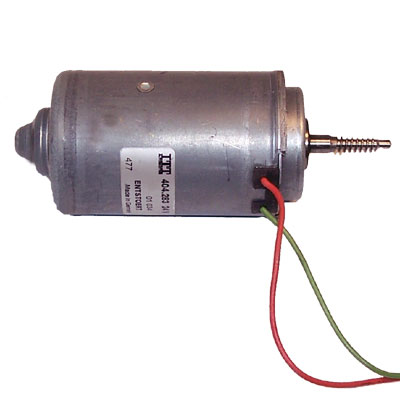
Frankenmotors arrive...
The first impression of them is that they are HUGE!
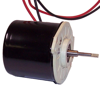 One of these would make 5-6 NEMA17's.
I fed 12v to one of them and it made a serious attempt to jump off of the work table. At 5v and roughly 1000 rpm (16 mm/sec) it is still putting out loads of torque.
I connected a 1.57v AA battery to the motor and it turns at a rate that looks to be about 300 rpm (5 mm/sec).
From there I went on to check amperage at the 3 voltage levels. Here is approximately what I got...
- 12v - 2.3 amps
- 5.5v - 2.1 amps (after motor warmed up)
- 1.57v - 1.7 amps (AA Battery)
Given the fact that this motor is a brushed DC motor measuring the resistance of the armature was a bit tricky. It appears to be about 0.7 ohms, however.
Tomorrow I plan to bolt one of these to the z-axis and cobble some sort of coupling to the threaded drive rod together. :-)
Friday, May 26, 2006
Digital servo
You can find how to build it on the RepRap wiki here.
Its bad point is:
- It overshoots and oscillates about the final set position when set to move at high speeds. Though this settles quickly.
Its good points are:
- It's cheap,
- It gives high torque for low (100mA) current, and
- It's accurate (256 steps per revolution).
I don't think it's quite ready yet to take the position of a stepper motor, but it may well be possible to make it good enough just by improving the control algorithm in the PIC - that is, with no hardware modifications.
It is certainly a good way of driving general devices with rotary feedback, and (I have yet to try this) it should allow rotation speeds to be precisely set and not to change with load.
Thursday, May 25, 2006
Echoing...

It's not wonderful, but it's a start and it's running at 9600 baud.
Shortly thereafter I massaged the VB.NET code for my serial comms programme.
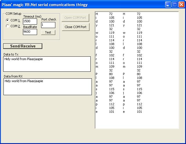
That enables me to interpret what goes out and what comes back and do things like throughput tests and the like and keep track of how reliable the comms link is. :-)
For my last act tonight I cranked the baud rate up to 19.2 to see if I had any problems. There weren't. :-)
Once I solid up the comms routines I will go on to implimenting the passthrough protocol for the token ring communications that Simon put together so that I can use my board on the same token ring with the rest of the boards. :-)
Tuesday, May 23, 2006
The frankenscrewdriver

The clamp holds down the switch so I can turn the thing on and off by just regulating the current - and recover the screwdriver if brother-in-law feels miffed :)
Vik :v)
Monday, May 22, 2006
Good news on the Java front
Vik :v)
Sunday, May 21, 2006
Simon & Vik's Bumper Fun Weekend Issue
I found a suspect inter-board cable and replaced it. That seemed to improve things a little. It appears that USB serial ports are still causing us trouble. I'll need another serial lead to attach the RepRap onto the PC with for the moment.
The electric screwdriver is now mounted and squirting happily. There is even an anti-backlash diode, which is needed now I'm using a TIP120 transistor to drive the extruder motor rather than a 754410. We discovered those don't have enough oomph. I also discovered they need an anti-backlash diode. Oh, and all the PC boards have sprouted smoothing capacitors.
The upshot: I can now print 2 layers repeatably. Why only two? Run out of 3mm filament again, haven't I? I've found plastic chopping boards are good for rolling it out between.
A fruitful weekend, and just as well as I'm off to Wellington next week for a couple of busy days. I can fit in a beer at the airport at 9pm Wednesday, Simon. My shout!
Vik :v)
Friday, May 19, 2006
LOL! Oh dear, here goes... plaas programs the PIC16F628
Thursday, May 18, 2006
Flagulation
"The design for ARNIE Mk 1 was flawed using a tension transmission for its z-axis movement: uneven tension behaviour caused jamming at the z-bed/vertical bearing surface which prevented the z-bed from working properly. This was exacerbated by an unstable structure, under-engineered and poorly build-orientated components, a critical modelling mistake which caused damage to critical corner supports and over-constraint of the z-bed’s movement."
I'm off to get drunk, and possibly wipe my face with my degree certificate.
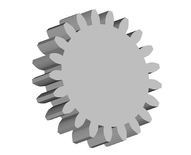
Helical gears back on again

So, no changes needed by the AoI guys after all - and we should be able to RepRap liquorice sticks :)
Vik :v)
Wednesday, May 17, 2006
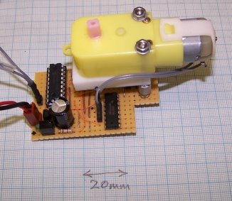
Magnetic Shaft Encoders
Vik has been rabbiting on about the magnetic rotary encoder chips from Austria Microsystems for ages, and so I finally got round to trying them out.
Guess what? They are beaut!
I rapid prototyped a holder for a small piece of stripboard to go on the back of one of the geared motors that I used for the Mark II Extruder, soldered one to the board, and put the lot together:

A small magnet is mounted on the motor's shaft, and Hall-effect probes in the chip encode the rotating magnetic field. Here's the scope trace:

There are two outputs which give quadrature (i.e. the phase tells you if the thing is going clockwise or anticlockwise).
I used the chip that gives 256 steps per revolution (the AS5035), but they go up to 4096. The signal is clean reliable and easy to feed into a PIC. And the circuit is simplicity itself (though it needs to be soldered by ants, as the chip is SMT).
For more details, see the Wiki here.
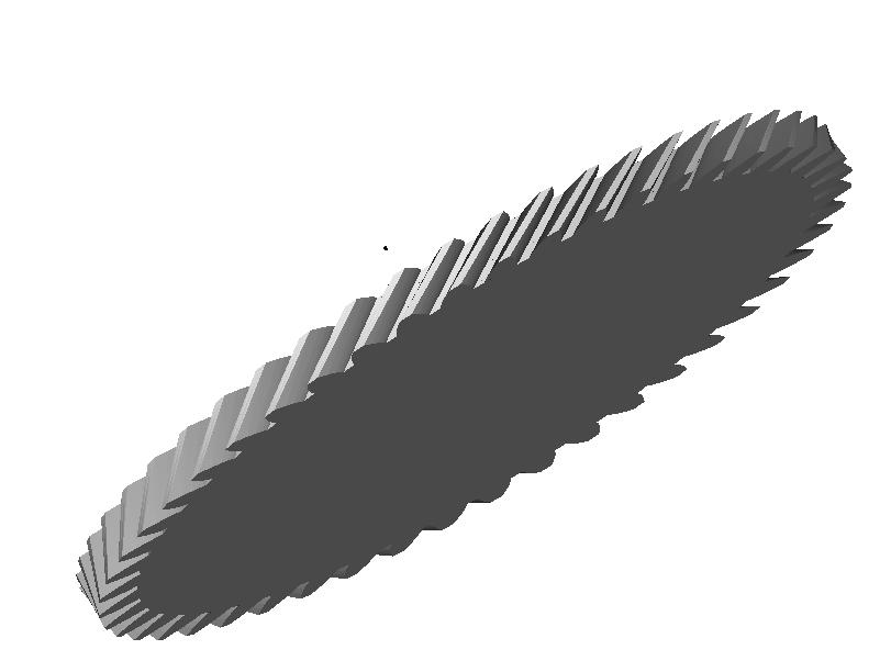
Steve Degroof asks a really good question...
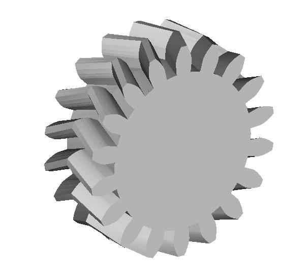
You asked a very good question. Turns out that we really can't even do a helical gear with the extrude feature as it stands. What we were generating only looked like helical gears. They weren't the real article since the helical twist wasn't helical, but only a straight line going in the same general direction.
I ran your spec just to see if it worked and this is what we got.
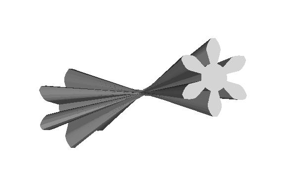
I gave the 6 toothed gear a 180 degree twist. As you can see the lines are straight, not helical.
Great catch, Steve. Anybody want to rewrite the twist option on the extrude code?
Tuesday, May 16, 2006
Gear reduction...
 After thinking about it for a while, I bought five of these to see if I can go at it more efficiently from high rpm to low. The MECI people had a 20% off sale on this month so I got 'em for US$4.76/unit.
That 1.8:1 reduction should make for a lot less hours on the Stratasys. :-)

A 31:17 toothed gear train for it looks quite reasonable.
And some gears not so good
So, next attempt will involve reformatting a Black & Decker 6V electric screwdriver - my rechargeable DSE screwdriver is far too nice to sacrifice :) Simon reckons it'll do well if the PWM output on the extruder is set to 50% but holding it in place is going to be interesting.
Still, lesson for Forrest on gears - make 'em wide and strong as the ratio increases!
Vik :v)
A gearbox for Godzilla...
Plainly, if I was going to keep the Godzilla design concept I had to have much more torque available at much higher rotational speeds. Some time ago I had acquired a pair of Siemens gearmotors designed to operate automobile electric windows. Those work on 12v power and have loads of torque.
Yesterday, I drove the Godzilla z-axis with one of them at 12v and today I ran it at 5v. There is no lack of torque. At 12v the Siemens gearmotor gets 56 rpm. That drives the z-axis at just under 1 mm/sec. The Mark II Extruder is designed for 4 mm/sec and I'd like to think that it can be pushed to 20 mm/sec without a major change in design philosophy. The design problem, then, is to leverage the Siemens gearmotor into getting 4 mm/sec and 20 mm/sec if at all possible out of the Siemens.
The obvious way to get that to happen is with a gearbox. Last week, at Simon's prompting, I wrote a script to design proper (involute profile) gears. That done, this week I've set about to design a proper gearbox for the Siemens.
My first design decision was to use a gear train rather than a simple pair of gears. This was more for space considerations than anything. It also conserves material in that going from 56 rpm to just over 1,300 rpm in one stage requires a rather enormous gear and puts some tremendous stress on the gear driving the threaded drive rod for the positioning stage.
I wanted to keep a constant gear ratio throughout the train to reduce complexity. Eventually, I arrived at a ratio of about 2.8:1. Assuming that the Siemens without a gear box can drive the z-axis stage at about 1 mm/sec, the resultant velocities at each stage of the gear train look like this...
Stage 0 - 1 mm/sec (56 rpm)
Stage 1 - 2.83 mm/sec (160 rpm)
Stage 2 - 7.8 mm/sec (440 rpm) {range needed for the Mk II Extruder}
Stage 3 - 22 mm/sec (1,230 rpm) {range needed for the expected terminal performance of the Mk II}
With that in mind after I got the gear design script running I started making some choices about tooth counts for the gear pair. Interestingly, using Adrian's rule of thumb that gear teeth need to be about 3 mm wide at a minimum it is very easy to use the script with that in mind. For example, if you need 24 teeth in a gear making the pitch radius 24 mm gets you a tooth width of just over 3 mm. Pi is a wonderful thing. :-D
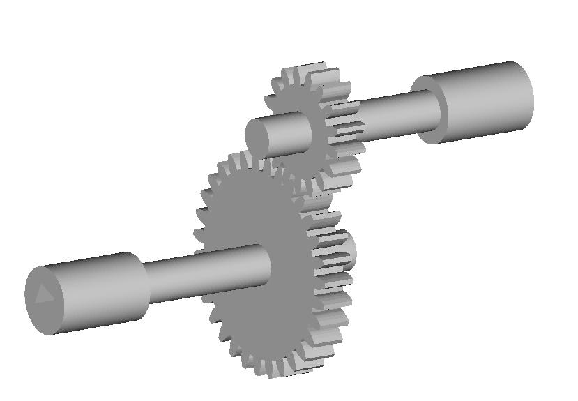
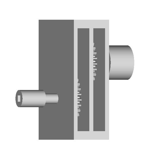
Anyhow, keeping Vik's advice about tooth counts in his tutorial in mind I arrived at a tentative gear pair with 31 teeth in the drive gear and 11 in the receiver. With that in mind I began a design charrette to see how the bits could go together. I decided to make a first shot at two stages so that I could run it at the Mk II's capacity with the option to add another a bit later. Here's what I got on the first cut...
You can see the coupling for the Siemens gear motor on the right and the coupling for the threaded drive rod on the left.
To give you an idea of scale the coupling collar on the right is 40 mm in diameter.
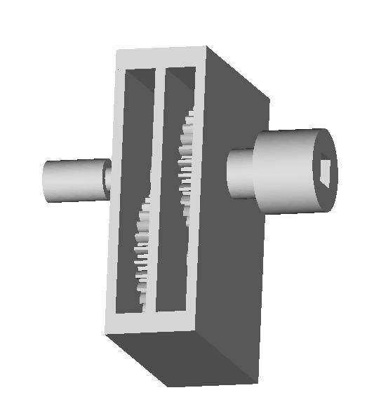 Tilting the model slightly to the left you can see the coupling collar receives a square drive shaft from the Siemens which measures 14 mm on the diagonal. That works out conveniently to a 9/16ths inch square rod. :-p
Tilting the gearbox slightly to the right you can see a bit more.
I've got to write a script to make a hexagonal profile since the collar connecting to the threaded drive rod needs to work with a long, hexagonal connecting nut. I used a square for now.
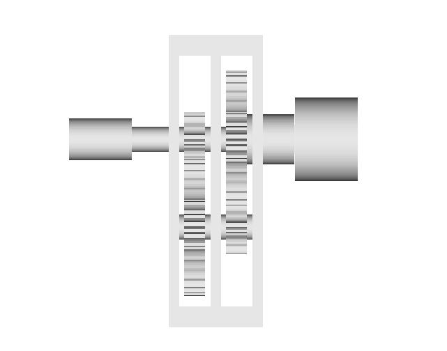
My initial feeling was to make the whole thing on the Stratasys. I did some tentative quantity surveys, however, and decided that Adrian wouldn't be glad of that given the volumes required and the cost of filament. Here's a look inside the first stage of the gearbox with the top and connecting collar removed.
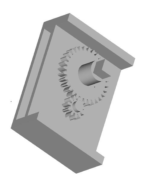
There is a lot of deliberate commonality in the parts for ease of manufacture. Here's a look at the gear train with the housing removed.

That two stage train gets you 7.8 mm/sec on the positioning stage. Add another stage to that using the same gears and you get 22 mm/sec.
After I got the first cut of the volumetrics of the design done it seemed quite reasonable that I could use standard sheet HDPE to make the housing if I was careful. I was reinspired by seeing one of Sebastien's references where a fellow built a whole CNC machine using plastic sheet.
http://biobug.org/cnc/klunk/
Mind, it would be better, I think, if the whole thing was done out of the same material on the Stratasys given the wayward nature of my drill press. :-s Still, there are other ways to control costs and booking time on the Stratasys if that's a limiting factor. :-)
Looking at the idea in a whole different way I'm sorely tempted to just get a heavy duty DC motor that runs at about 2-3,000 rpm and just step it down by half.

This one from MECI...
http://www.meci.com/product_info.php/products_id/4200577
...draws 2.25 amps and produces 2370 rpm. A simple 1.8:1 gear reduction would produce 20 mm/sec positioning speeds. It costs U$5.95.
An even cheaper and more powerful one by all accounts from MECI...
 ... goes for a ridiculous US$3.95 in one-off quantities.
I'm spoiled for choice here. I feel like the proverbial donkey between two piles of clover hay. :-s
Refill of the syringe
The plumbing pipe is fixed into a carriage, and held in place with two plastic rectangular traps (which go into the two holes seen in the side of the body). The whole mechanism is allowed to swing away from the body, enabling the plunger to be removed from the piping and the piping contents (i.e. support material in the form of Polyfiller) to be replaced or refilled quickly.
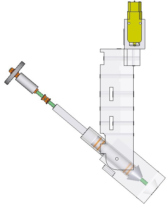

Then the mechanism is placed back into the carriage, which is locked up and the two traps slid back in place. All done in under a minute.
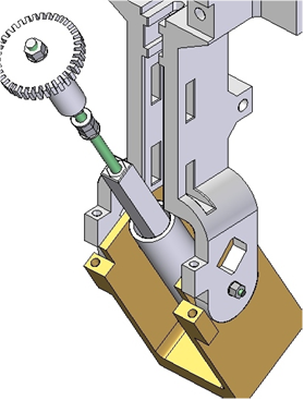
Support material extruder

All the parts (except the nuts, bolts, threaded bar, nozzle and worm and wheel) were manufactured using the Stratasys Dimension RP machine.
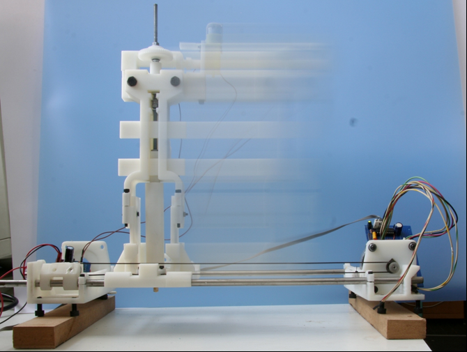
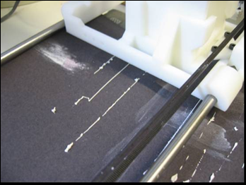
The motorised syringe was integrated onto Ed's axis and it allowed straight line deposits to be made.
The current deposition rate is 4.49mm3/s with the 50:1 gear ratio (12V power), however the deposition rate can be significantly increased (or decreased). The plumbing pipe is 100mm in length and stores 18ml of Polyfiller.
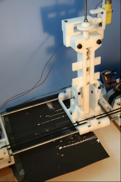
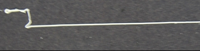 Desposit of Polyfiller using the motorised syringe.
Some work is needed on controlling the start and finish of deposits, but this is just a matter of starting the syringe before the axis and timing the deposition and movement correctly, something easily done with a few further tests.
It is also possible to utilise copper plumbing pipe should heating of the pipe contents be required.
Support material conclusions
Having had icing sugar proposed to me as an idea I quickly found that it was unable to be deposited at 0.5mm resolution and that it took a long time to set (over 1hour).
However, Polyfiller was the perfect substance. I was able to deposit Polycell Fine Surface Polyfiller from a 0.5mm nozzle, creating a perfectly consistent line, which set hard within 2 minutes.
 An initial problem was that Polyfiller, once set, would not fully remove from the surface of an ABS part(although it would remove from the syringe nozzle if placed in warm, soapy water within an hour or so of exposure). But Adrian's use of vegetable oil as a releasing agent on the ABS cude (Blogged in April 2005) resulted in using it (veg oil) to see if it would aid Polyfiller's removal from ABS parts, which it did perfectly.
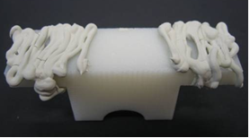 ABS part (previously coated in veg oil) covered in Polyfiller.
 The same part after the Polyfiller had been removed.
The vegetable oil was deposited as a thin layer using a brush, and it was also possible to separate Polyfiller layers from themselves. It could be best to deposit the oil from a felt tip pen, replacing the ink with oil, which could then be simply deposited as a thin layer in the FDM process.
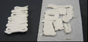
Ignore the cracked layer (it was cracked before the layers were separated).
The pictures and information regarding the deposition mechanism for the Polyfiller will be added soon (next few hours).
Godzilla vs the Siemens gearmotor...
The Siemens gearmotor cranks 57,600 gm-cm of design torque vs the NEMA 17's 3,240. While I was having to constantly adjust the z-axis positioning stage with the NEMA stepper to get it to work at all, it was all that I could do to keep the thrust rod from unscrewing itself from the positioning stage with the Siemens motor running using about the same amount of current.
The "load" of the positioning stage, such as it is, made no difference to the design spec'ed 55 rpm for the motor at 12v. That motor speed gives me, 0.87 rps on the z-axis positioning stage, about what we're currently getting with the NEMA 17.
It seems kind of silly to gear the Siemens motor down to 55 rpm and then gear it back up to maybe 12-1400 rpm so that I can push that threaded drive rod at 15-20 cm/sec, but hey... these motors are cheap, efficient and tough. :-)
Monday, May 15, 2006
Limits on the gear script not as bad as thought...
 I reinstalled both and I can now generate at least 48 tooth gears and helical at that.
I then decided to see if I could double that tooth count, so I went to 96 teeth and dropped the pitch angle to 14.5 degrees so that we didn't get weirdness in the profile.
 That worked fine, too. I pushed it again to 128 but at that point the triangular mesh feature wouldn't turn the profile into a surface for me.
At 96 teeth you're talking about a 180 mm diameter gear if we are to keep the teeth at 3 mm. That's pretty big.
It's slow, but it works. :-)
Thoughts on scaleable RepRaps...
 Now that we can make involute profile gears, why don't we make racks to go with them?
If you split the rack lengthwise and made it in sections of maybe 200 mm it would be relatively easy to design a sliding dovetail connection so that two lengths could be assembled to make one rack twice as wide. Stagger these sections and you could make a rack as long as you desired from 200 mm sections.
Put holes in the sections that were a little wider than the bolt that went through them. Reprap an alignment template jig so that you could hold the two halves together while you secured them with nuts, bolts and lock washers and you are good to go.
Lay a printed linear encoder strip beside your rack and you have a track that a positioning stage can use.
A bunch of things have been bothering me lately. We've got good control boards for steppers and we've got good steppers with magnificent angular resolution. Unfortunately, stepper torque drops like a stone when you try to run them quickly. We stick these onto threaded rod drives like we see our CNC hobbyist friends using. These guys are running their systems very slowly because they are doing things like cutting patterns in a piece of wood with a router. When you are doing that sort of thing speed is not what you want, so steppers work magnificently.
We're not taking away material, though. We're laying it down. Our productivity depends on how fast we can extrude material. The Mk II extruder currently operates at 4 mm/sec. At a 50% duty cycle it will put down 1 kg of polymer/month. We need to be doing five times that to have a viable system. The current Mk II technology can probably be pushed into doing that by putting more energy into the extruder head and amping up the feed.
Our current positioning stages are more of a problem, however. We can do about 1 rps with our steppers. Using threaded rod positioning systems that means we can move about 1 mm/sec. If we try to go a lot faster than that our torque goes away. We need to be doing twenty times that.
The problem isn't with our control theory or with the steppers. Those are fine. The problem is the use of threaded rods for positioning. Threaded rods are fine for the vertical axis. Speed isn't an issue there. For the horizontal axes, however, they don't work all that well.
Why not rack and pinion?
Most of the CNC equipment that I've seen uses rack and pinion. If we were to use our existing steppers to drive rack and pinion positioning we could get the speed we need without a lot of drama and without trying to make our control boards do things they were never intended to do.
We're not trying to carve anything so our positioning systems can be light. Ed's string machine had a lot going for it in terms of using the method for keeping things aligned while applying force asymetrically. I think where the trouble began is when he tried to apply motive force to the cables. In Godzilla it would be relatively easy to use drafting board cable and pully technology to reduce the number of steppers needed and the complexity of the control system.
Now that I can design gears I'm probably just seeing everything as problems with gear problems. :-p
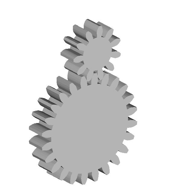
Meshing gears... Simon's question...
Can we produce gears of different sizes that still mesh correctly with each other?
I think so. This routine figures the tooth placement from the pitch radius which, if I understand it correctly, is the place where the teeth of meshing gears interact.
What you do is decide on a pitch radius, say 130 mm and 13 teeth. Then you if you wanted a 13:6 gear ratio you'd go for 60 mm and 6 teeth.
I did that and then placed the two gear centers 60 mm + 130 mm away from each other. As you can see they mesh very nicely.
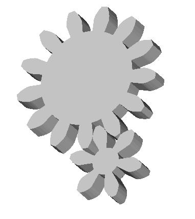
Okay, Simon! Make us some gears! :-D
Here's a gear pair with a 24:11 ratio. It took me about a minute to design it on Art of Illusion.
Heh, heh, heh... :-D

We have an involute gear script!
Just got past the last peculiarity of the Beanshells scripting language and the gear profile displays. It would have never been possible without Vik's cog script as a starting point and his advice at critical moments. I'll be passing copies of the script around to the team as soon as I do a little code cleaning on it.
Sunday, May 14, 2006
Something that looks like square and hexagon!

There are 3 layers, roughly a whopping 0.5mm thick. The Z-axis was handled manually between layers, otherwise it was completely automated. The nozzle was the same huge 1.5mm worm-squirting monstrosity (about 0.5mm dia) as last time. There is video if anyone is interested.
The first edge of the square failed to extrude every time, which we'll have to deal with when we start calibrating things. But for a first-off attempt with next to no anti-backlash and zero calibration I'm pretty pleased. I think we're on to a winner here.
Brandy and hot bath time :)
Vik :v)
Busy weeked with little to show
* Progress the virtual comms and testing infrastructure (see svn branch), which will soon allow me to complete the remainder of the comms infrastructure. This will eliminate those occasional pesky errors.
* Updated my old graycode wheel perl script and put it into the reprap subversion repository. See reprap/misc/graycode in subversion.
* Using new graycode script, produced a template for a bi-directional position sensor for a DC motor controller.
* Tried out my previously imaginery process for turning PC artwork into plastic objects, pre-reprap. Potentially a useful process for "repstrapping" with kitchen level technology.
* Some work on reprap application to eliminate most of the hard coded magic values and make them customisable via the preferences screen.
* Tested my old thermoplastic bushing idea for my old repstrap design. Mixed success. It fits so perfectly that it doesn't turn very easily, but it certainly removes any play in the threaded rod. Needs more work...

This is what my 2-bit graycode bi-directional position sensor currently looks like. It's so simple it could just as easily have been created by hand, but using the script allows for very simple changes to diameter, spacings, etc. In fact, these are the parameters for the graycode script. It's fairly versatile:
* Number of bits (arbitrary number)
* Wheel dimension (mm)
* Inner dimension (mm)
* Strut size (mm)
* Span (degrees). For angle sensors, it's often useful to use less than the full 360 degrees.
* Stagger (~mm). Stagger between sensor positions. This allows bulkier sensors to be used and the graycode rings are offset. The application also produces a cutting/placement guide that should where the sensors should be placed, which is pretty essential when staggering.
* Resolution (dpi)
* Portion. Fraction of wheel to include (entire wheel is not necessary if used for angle measurement and using less than 360 degree span)
* Reps. The number of repeats of the graycode pattern around the wheel. This is the new feature needed to make a mechanically balanced wheel for a fast turning position encoder.
I started to add STL support a while back, but that's not even close to complete. The primary output is a bitmap ready for printing on a laser printer.
My conceptual process to turn these into actual plastic objects was:
1. Print out object onto tracing paper with a good laser printer (new toner). Inkjets don't work as the inks are UV transparent.
2. Take a piece of thin steel, and spray it with PCB photo-resist. Bake dry for impatient people like me.
3. Place tracing paper pattern on metal. Cover with thing sheet of transparent plastic (not glass which is UV opaque) to hold pattern close to surface. I used the plastic from a CD cover, whatever that is.
4. Blast with UV light
5. Use developer to bring out the pattern on the metal
6. Using electrolysis, "melt" away the unprotected part of the pattern, leaving a thin metal version of the pattern. Alternatively use copper sheet, and use ferric chloride to remove unwanted metal.
7. Press metal pattern into molding plasticine. Pressing it deeper makes a wider part.
8. Create plaster of paris mold from plasticine and let it dry.
9. Melt plastic into mold
My goal was to produce one of the gray code sensor wheels and Forrest's sample involute gear pattern.
I tested steps 1-5 but it seems my photo-resist is a bit too old now. In fact it's quite a few years beyond it's "best by" date, so it's time to order some more. The patterns were not holding well enough for me to carry out the remainder of the steps. I will try again when I get some more photo resist, but all the local suppliers seem to have stopped selling it. I'll try RS.
I tested step 6 using several different electrolytes. Plain salt (NaCl) was the fastest but has the downside that it produces some chlorine gas, so ventilation is a good idea. It doesn't need much salt though. I hand painted a pattern onto a piece of metal, and the pattern was cut out with good fidelity. It takes quite a few hours to cut, so you have to have some patience. It makes the more conventional ferric chloride approach more appealing if I find or make some plain copper sheet. I have lots of ferric chrloride, so I might try that next time. The electrolysis approach produces nice steel templates and just seemed cooler :)
I have previously tested steps 7 to 9 using PLA to produce some gears. It works quite nicely but destroys the plaster mold so it can only be used once. It also takes a bit of scraping to get excess plaster off the gear before it will work nicely.
So all steps tested, but not quite working yet.
The solution to yesterday's puzzle

So that's what it should look like! :)
I had a break in one of my 12V power tracks (reinforce them all with solder, boys and girls) and a stepper moving too fast. The combination of those two produced yesterdays "Blobs From The Dark Lagoon". I think I still have my Y-axis reversed.
I guess all that's left to do now is roll some more CAPA and have another go at extruding. We'll see how far I get tonight.
Vik :v)
Saturday, May 13, 2006
Time for a laugh, and a smile
So, how about a picture:

Yeah, I know. Not a lot like a hexagon and a square - except in post-LSD nightmares. I'll give you a couple of clues: The hexagon is bigger than the square, and they're the wrong way round because of my X axis inversion. Also too short because of my Y axis mis-scale. Also very mucked up because the infil is meant for a smaller nozzle. Also the first time anyone has done this...
Vik :v)
Friday, May 12, 2006
And here by popular request, boys and girls...

I had forgotten how finicky a business it is to create a rectangular to cylindrical coordinates conversion routine that uses the arctangent function that's good for all four quadrants of a 360 degree range. That took an interminable amount of time... all special cases. :-s
I didn't add fillets and roundings, mostly because for the size teeth we've been talking about, viz, 3 mm or so, I doubt that our repraps will even see that sized detail. I also used straight lines for the base between teeth and the tooth crowns for the same reason. If this proves to be a problem I'll expand the code. I'd rather not get caught up in guilding lilly exercises just now. I just want to make a drive train.

It's always fun to push design methods to extremes. This one from the University of Luleå that I've pirated for our purposes to design involute profile gears gives some really neat results at extremes as you can see with this 5 toothed gear. If we were really going to make gears at the extremes then fillets and rounds would be much more likely to be required. As it is, though... :-)
There's a contract final report to write up and turn in in the morning along with an invoice so I won't be getting back to this till tomorrow afternoon or evening. I'll be trying to sort out the design process so that we can make gears that mesh properly with less effort than is presently the case. If that works I'll clean up the code logic and try to translate this into Java this weekend. I've got Vik's excellently written cog script as a starting point, so I'm not expecting a lot of problem with that. Wish me luck, though, after all I didn't think that doing a simple cylindrical to rectangular coordinates conversion was going to be such a big deal beforehand, either. :-(
![]()