Thursday, April 30, 2009
A different approach to extrusion

Wednesday, April 29, 2009
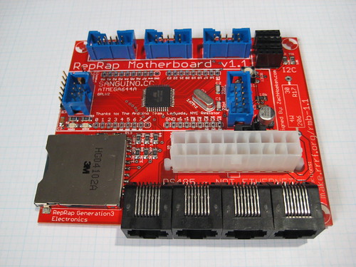
Introducting the RepRap Motherboard v1.x
This is another board that has been in development for quite a while that I have done a pretty sad job of communicating to the community about. Well, it's now ready for primetime and a bunch of people have been using them for a while.
The idea on this board is to consolidate the stepper control onto a single board, give it a comms network to control modular 'slave' devices which can control extruders, etc, and also to give it an SD card slot as well as some other cool features. It's based off the Sanguino design.
Anyway, I summed it up much better in the wiki page:
This board is the brains behind the Generation 3 Electronics. The heart is a Sanguino which is an Arduino-compatible board that is powered by an ATMEGA644P chip. It has connectors to hook up all the various peripherals that you'll need to drive a RepRap machine. It has headers for three stepper drivers, as well as 4 RJ45 connectors for Extruder Controller Boards. Not only that, but it has an SD card and a connector to hook it up to an ATX power supply.
Some highlights:
* Onboard atmega644p - 64K flash space, 4k ram, 32 I/O pins, Arduino compatible.
* 3 x Stepper driver connectors with min/max inputs.
* Built-in SD card socket for printing from file and buffering large print jobs.
* RS485 connection for noise-free communications with extruder / toolhead controllers.
* ATX power connector for power. It can also turn the power supply on and off.
* Headers to allow existing Sanguinos to plug straight in.
* I2C headers for simple hookup of external peripherals.
* On/Off switch for instant-kill and simple control of the entire system.
This board was developed by the RRRF and is available for sale from MakerBot Industries as a kit. They will also be available fully assembled in a month or so.
DIY chip fab
This blog is for RepRap progress, but sometimes things happen elsewhere that deserve a mention too.

So, thanks to Julian Skidmore for telling us about Jeri Ellsworth, who is doing amazing stuff...
Check out these two links to her work:

So, thanks to Julian Skidmore for telling us about Jeri Ellsworth, who is doing amazing stuff...
Check out these two links to her work:
http://www.flickr.com/photos/jeriellsworth/2835524263

and

http://www.flickr.com/photos/jeriellsworth/2835459827
Thursday, April 23, 2009
Skeinforge Support
I've been trying out the support material in Skeinforge and said I'd post some pictures. The settings have not been fine tuned but I'm still very pleased with the results. The object was a simple test shape it is 100mm tall and 30mmØ the columns are 8mm x 2.5mm and the column length is 75mm. So quite a delicate shape.
Skeinforge generated a good support structure and it printed OK with our firmware the head goes to a rest position every time the temp changes so it did this approx 500 times (twice every layer) as the support went down at 235°C and the Print at 250°C this in turn lead to lots of hairs coming from the print. I resisted removing them during the print and wanted to know if it would work with Zero intervention, it did :-)
The print took about 1/2 hour to clean up and the support was better stuck than I would have liked, in removing it I broke the columns, this was a little upsetting up until the point I realised I could glue it back together and the join was invisible and as strong as the rest of the model, I also figured that it was not an unacceptable solution as the end result is a very acceptable print (well I think so for zero tuning).


Ian www.bitsfrombytes.com
Wednesday, April 22, 2009
Wedgewood X Assembly, Thumbnail Edition
 Having drilled my left thumb and nail for M3, I'm now back in the workshop once again and working on Wedgewood. I promised the guys in the #reprap chartoom on IRC (Chatzilla or similar needed) that I'd give a quick update. As you can see from the photo my good camera is broken too, other than that there is a railcar-like X carriage and on the right a contrivance to dangle it all from the Z axis.
The wheels are made from two skate bearings with a washer between that is thinner than the rail. This causes the bevelled edge of each of the bearings to run on the corner of the top of the rail and self-centre. Runs nice and smoothly, should also be robust enough to dampen oscillations of the drive rod. Yes, that is a Ponoko lasercut extruder (from an old extruder kit) plugged into the X Carriage - both the MDF carriage and lasercut extruder are compatible with the Darwin exchangable head holder. I love standards :)
The stepper will be screwed to the block on the far right and coupled to the horizontal threaded rod. Probably put a bearing in there to reduce play too as I'm using cheap stepper motors.
Oh, I can also report that brazing thermocouple wire doesn't work - it melts way before the brass. I'll have to locate some silver or 95/5 solder. Flash-welding the stuff is looking more convenient by the day.
Vik :v)
Labels: wedgewood, x carriage
Monday, April 20, 2009
Introducing the Extruder Controller v2.2
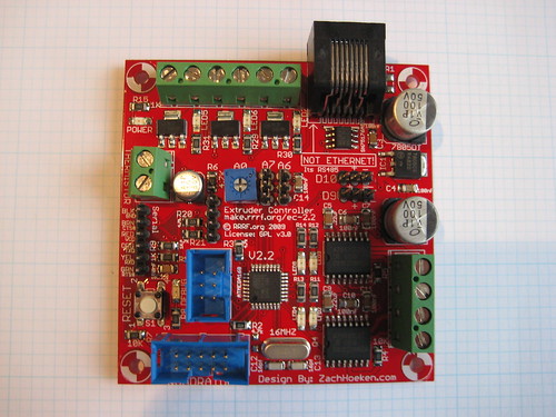
This board has been under development by the RRRF for quite a while, and it's gone through a few different revisions before I felt it was ready for prime-time. This board is a major component part of the new Generation 3 RepRap electronics, and I'm really happy with how it turned out. You can read the full documentation on the board on the RepRap wiki. Oh yeah, and the design is up on Thingiverse if you just want to check out the files quickly.
One of the major problems with the Gen2 electronics is that everything was running on a single Arduino, and that chip just didn't have the power, the pin count, or the memory to run a RepRap machine really nicely. So, with Gen3 I decided to swing the pendulum back a bit towards the Gen1 boards which were completely distributed. With the Gen3 stuff, its a happy medium: there is a motherboard (which I'll blog about later this week) that can control various slave devices (such as this Extruder Controller). Each of them has its own processor, so they can do things independently.
For example, with the old system, we had to have a temperature check in the same loop that was doing the stepping algorithm. It had to check the temperature between every step otherwise it would either heat up too much or cool down on long moves. This resulted in a slowdown at faster speeds which was really a pain in the neck. However, with the new system, the Extruder controller is responsible for handling temperature and the Motherboard basically just sets it and forgets it. It simplifies the design of both firmwares and life is good overall.
To get into some nitty gritty details, the Extruder Controller v2.x boards have an Arduino onboard (atmega168) and use RS485 to communicate with the motherboard (noise tolerance!). Here's a blurb from the wiki where it has been fully documented:
* Onboard atmega168 - program it just like an Arduino because it is an Arduino.
* 3 x MOSFET drivers for controlling up to 14A @ 12V. Perfect for heaters, fans, solenoids, etc.
* 2 x H-Bridges capable of up to 2A each. Control 2 motors, or control one stepper motor.
* A temperature sensor circuit for reading the standard 100K thermistor.
* RS485 connection for noise-free communications with the motherboard.
* IDC header for connecting a Magnetic Rotary Encoder.
* Polarized ICSP header for simple, easy programming.
* It mounts directly to the Pinch Wheel Extruder!
* It is plug and play with the RepRap Motherboard.
If you want to use one on your machine, you can get a kit from the MakerBot Store. It is a SMT based board, but don't let that scare you off. It's actually pretty easy to get it soldered up. If you absolutely refuse to do SMT, we're planning on having them fully assembled in a couple of months which will make things easier.
Sunday, April 19, 2009
First reprapped circuit

Ed and I have a final-year student - Rhys Jones - who's working on RepRap for his MEng research project. He's been taking the old idea of depositing metal in channels and an observation of Forrest's and Nophead's (that you don't need a low-melting-point alloy because the specific heat of metals is so low that they shouldn't melt the plastic anyway).
He's adapted the pinch-wheel extruder to drive ordinary solder (without core flux - that just makes a mess) down through a thin tube with a nichrome heater wrapped round it.

Here's his first circuit. It was made entirely automatically by the RepRap machine. It's a bit blobby, but...

It's easy to put the components in from the other side. It's the RepRap opto endstop circuit.
Finally, here it is fitted to the RepRap machine that made it and working:
Labels: reprapped electronics
Saturday, April 18, 2009
Bowden extruder concept
Anyone who's designed a 3D printer knows that one of the primary constraints is the geometry of the extruder. If the extruder is mobile then it has a big impact on the final volume of the ‘bot. I've always been a fan of making the final printer as small as possible (cup cake’s footprint’s pretty sexy), so to that end I have been looking at options for tiny extruders.
I think the key here is to decouple the nozzle from the drive mechanism – it is the motor and its transmission which takes up a big proportion of the extruder's volume. Using some PVC sleeve (3.3mm ID) I decided to follow Forrest’s previous attempts at using a bowden cable approach to make a flexible link between the two. The motor is anchored to the side of the bot and drives the 3mm PLA filament (A) through one end of the tube (B) down the flexible tube (C) which terminates in the hot nozzle (D).

Decoupling massively reduces the necessary volume of carriage which in turn enables a much smaller machine. It also takes a lot of weight out of the moving parts.
Two trade-offs are:
- Increased power will be needed from the extruder motor to overcome the friction in the system (though we’re only running our NEMA 17 pinch-wheel extruder motor at 30%, so we have some capacity there. Also, we could use Teflon sleeve to reduce the friction co-efficient as a last resort).
- Stretching hysteresis in the sleeve may affect print results (this is down to finding a sleeve stiff enough but still suitably flexible for print movements).
Unfortunately I’ve knackered the electronics on my machine so I can’t test this yet, but finger tests feel good. Thankfully Adrian’s offered to fix me up with some of Zach’s latest boards while I’m away for Easter so watch this space.
Monday, April 13, 2009
Get your stepper to put splines on its own shaft

The new pinch-wheel extruder needs to be able to grip the plastic filament that it is extruding to drive it down into the melt chamber. A splined stepper shaft does that nicely, but splined steppers are both rare and expensive.
Here's how to get your stepper to spline its own shaft...

The only special equipment needed is a Dremmel or similar minidrill. The rest is stuff like bits of wood, cable ties, and an old door hinge...
See here for full instructions. The top picture shows the results.
Labels: extruder, pinch-wheel, pneumatic stepper motor, splines
Sunday, April 12, 2009
Getting a handle on milling accuracy

In which your narrator gets a handle on the everyday accuracy of the total tool chain from Art of Illusion to the milled product... do you want to read more?
Saturday, April 11, 2009
By your powers combined, I am KAPTON PLANET

Some say that necessity is the mother of all invention, and I'd have to agree with them. When we decided to start MakerBot and launch a complete 3D printer kit for under a grand I knew we had a lot of work cut out for us. Transitioning the RepRap technology from a research project to something that is a product presents many challenges. One of my main tasks was preparing the Plastruder MK3 for production.
I had been developing the 3rd generation extruder as part of RepRap for a while and it worked great. However, there were parts of the process that just weren't suited for a DIY kit at all. The main problem was attaching the nichrome wire and thermistor to the heater barrel so you can accurately control the temperature. For years (literally) we've been attaching the nichrome wire to the heater barrel with some form of high temperature cement: first JBweld, then with fire cement and stove cement. The latest revisions for doing this all work, but I didn't like them.
Why? Because they are horribly messy. Stove cement is an awful, black compound that stains and is probably toxic as hell. Fire cement only comes in 55lb bags. Stove cement only comes in giant 5 oz tubes. All you need is a tiny amount of this stuff to insulate and bond the nichrome. Plus, it is a very delicate process to wrap the nichrome and then apply the goop the whole time hoping that you don't jiggle it the wrong way and have everything fall apart. If some of it gets in your extruder nozzle? Game over. Oh, did I mention that you have to let it sit OVERNIGHT to fully cure? You're all fired up to build your extruder and WHAM! Instant timeout.

So, what did I do? Well, aside from the intial panic, I decided to try about 10 different techniques and go with the best one. I tried all the various forms and techniques for dealing with high temperature cement when I stumbled upon this blog entry by Limor Fried of Adafruit fame. Something there sparked my eye: it was here use of the Kapton tape. Up until now I had not even heard of it, and maybe its the same for you as well.
After doing a few hours of research on it and realizing it was PERFECT for what I wanted, I quickly ordered a tiny little roll from McMaster for $4. As soon as I got it, I built a heater barrel assembly from it. It took me 15 minutes and I was able to use it right away. It was the fastest and easiest extruder build I had ever done. Usually when I built extruder barrels, I had to use some sort of tape to hold down the leads while I build it anyway. With Kapton tape, I didn't have to remove them and they simply became an integral part of the extruder itself.
Wow, that turned out to be longer than I thought. I managed to find a good supplier of Kapton tape so you can get it from the MakerBot store, and it will be a part of our upcoming Plastruder MK3 Kit which will start shipping Monday.
Thursday, April 09, 2009
RepRap hits Parliament
A few weeks ago it was the final round of the "Science Engineering and Technology for Britain" awards. I was there waving the RepRap flag, and it just so happened to be held in the British houses of parliament! I got to tell a lot of MPs about our work and reactions were as brilliant as usual. Here's my poster...

and here's a really terrible shot of me after too long at the free bar, with an MP from north Wales.
.JPG)
I didn't win (obviously... did I say there was a free bar?) but it was very interesting to delve so physically into the political structure of my country. (What I saw restored a lot of my faith in our society... it may not be perfect sometimes, sometimes a long way off, but people are genuinely trying spectacularly hard to make it better – that alone seems to me to be a wonderful thing about being a human).
Cheap linear bearing hack
I don't know if this is useful to anyone, but I recently tried using the inner diameter of a skate bearing as a linear bearing on an 8mm (or 5/16") ground bar. It slid up and down really well - good enough to be used as a bearing in a mechanical design. I'm not sure if this scales yet (i.e. will a 625 bearing work on a 5mm bar too?) and performance might not be quite as slick as a proper bush/recirculating linear bearing, but man it's such a cheap hack!

From the self-manufacturing point of view, having recently (personally) accepted the ball-bearing as a vitamin part I'm finding this capability to be awesome.

From the self-manufacturing point of view, having recently (personally) accepted the ball-bearing as a vitamin part I'm finding this capability to be awesome.
Sunday, April 05, 2009
A gripping read
I have done some work comparing the amount of grip that different extruder drive methods achieve. I measured the amount of force the following devices gave before the filament slipped: -
The results where as follows: -
The red figures are lower or marginal compared to the force required to extrude 0.5mm filament at 16mm/s.
More details in my blog hydraraptor.blogspot.com/2009/03/pulling-power and hydraraptor.blogspot.com/2009/04/all-torque-and-no-traction.
| A 4mm splined shaft. |   |
| A 13mm timing pulley |  |
| The original M5 thread drive |  |
| A 13mm knurled wheel |  |
| A 13mm threaded "worm" pulley |  |
The results where as follows: -
| PCL | HDPE | ABS | PLA | |
| 4mm splined shaft | 2.5 Kg | 3.0 Kg | 5.0 Kg | 7.5 Kg |
| 13mm timing pulley | 4.0 Kg | 10.0 Kg | 8.5 Kg | >8 Kg |
| 13mm knurled wheel | 5.0 Kg | 10.0 Kg | 12.0 Kg | >12.5 Kg |
| 13mm M4 worm pulley | 6.0 Kg | >12.5 Kg | >12.5 Kg | >12.5 Kg |
| 13mm M3 worm pulley | 8.0 Kg | >12.5 Kg | >12.5 Kg | >12.5 Kg |
| M5 thread | 9.0 Kg | >12.5 Kg | >12.5 Kg | >12.5 Kg |
The red figures are lower or marginal compared to the force required to extrude 0.5mm filament at 16mm/s.
More details in my blog hydraraptor.blogspot.com/2009/03/pulling-power and hydraraptor.blogspot.com/2009/04/all-torque-and-no-traction.
Labels: extruder design
Thursday, April 02, 2009
Now Available: Stepper Motor Driver v2.3

This new board has been in development by the RRRF for quite a while as we've been trying to get it just right. The v2.3 design has homed in on the excellent A3982 stepper motor driver chip from Allegro. This chip is cheap, reliable, and excellent. This new board actually drops the price of EACH stepper driver by about $10 and makes it easier to build. Its surface mount, but using the hot-plate soldering method, you get a much nicer board and I've actually found it to be much easier than soldering up a million through hole components.
This board has the same pinouts as the previous Stepper Motor Driver v1.2 board, so will be a very simple upgrade if you're so inclined. The pinouts for the stepper connector, opto endstops, IDC connector, and power connector are all the same. Yay for standard interfaces!
Thanks to Lou Amadio, and the RepRap team for help in refining this board.
Anyway, you can get kits and pcbs from MakerBot Industries. We'll have fully assembled boards in a few months as well if you're too stubborn to learn SMD soldering and DIY.
Oh, and if the new hotness of the board isn't enough, check out this video of the new stepper tester code I wrote to go along with it. Tell me that doesn't make you smile and I'll frost you a cupcake.
Test Pattern 8 from MakerBot Industries on Vimeo.
Wednesday, April 01, 2009
more WeDge
Hi! It’s been a bit mad getting all the admin out of the way this end, but finally I get to post what I’ve been tinkering with recently: my take on the Wedge design exercise (from a previous post, here).
Vik’s been testing out the concept in the real world and it looks like things might check out! Meanwhile I’ve been working on incorporating self-manufactured parts into my take on the concept, below (if you want a virtual fly through of the design, check out the notes at the end of this post).

Design notes:
- This is a first cut only! Still some elements to be included. Also some things are just in here out of convenience. For example, round bars are used as bearing surfaces because I have them in stock. Will move over to Vik’s idea (angle iron is more ubiquitous) when fully proven.
- Uses NEMA 17s
- Top studding will be used as tool-change gantry.
- Footprint is 500 mm x 500 mm
- Woking area is currently roughly 250 mm x 200 mm, this will be optimised of course
Virtual Reality viewing notes:
I can recommend using the Cosmo Player VRML plugin with the Firefox browser (though if that doesn’t work out, try here)
Once you’re set, simply open this file.
Ed Sells

Well done to Ed, who's just passed his PhD viva voce. He has to make a couple of minor alterations to his thesis, and then he'll have his PhD. So, from the Bath University graduation ceremony this summer, he'll be Dr Ed...
Reprappers (and anyone else...) who wish to add their congrats can do so via:
skinnyed at gmail dot com
![]()