Friday, August 11, 2006
Infilling...
After thinking about all of the drama involved in a cross-hatching scheme I got to wondering what would happen if I just used the perimeter tracing routine over and over to do the infill. Here is what happened. 
I first tried the gears since I thought that they would be the most challenging.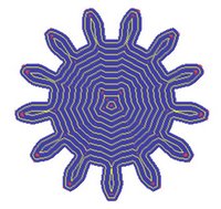
Remarkably, there was very little in the way of voids left in the extrusions.
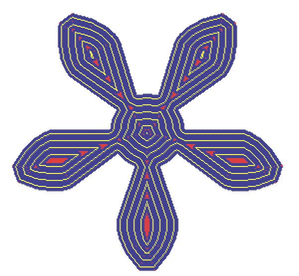
The first serious problem I had with voids occurred with the non-convex example that I did for Adrian.
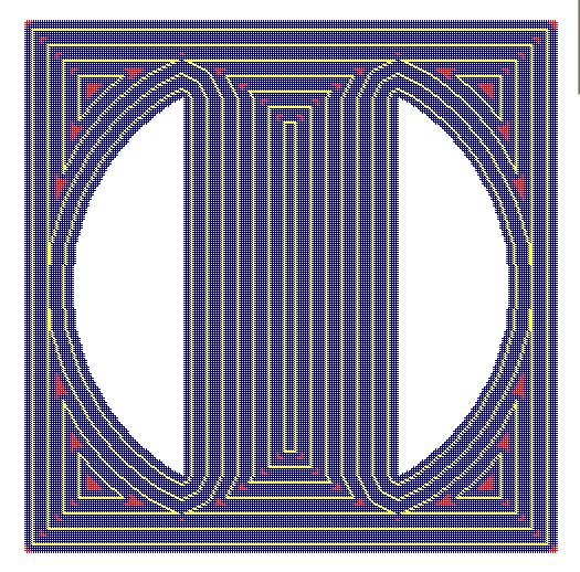
This last slice from the bead support structure I just threw in because I liked the pattern it made. I was an architect for a long time, so sue me. :-P
I am wondering now if it would be possible to fill the more egregious voids by simply making passes over them with the Mk II with the extrusion rate throttled down for the translation speed and sort of squeeze polymer into the voids using the already extruded walls as molds.
I first tried the gears since I thought that they would be the most challenging.

Remarkably, there was very little in the way of voids left in the extrusions.

The first serious problem I had with voids occurred with the non-convex example that I did for Adrian.
This last slice from the bead support structure I just threw in because I liked the pattern it made. I was an architect for a long time, so sue me. :-P
I am wondering now if it would be possible to fill the more egregious voids by simply making passes over them with the Mk II with the extrusion rate throttled down for the translation speed and sort of squeeze polymer into the voids using the already extruded walls as molds.
Comments:
<< Home
Interesting patterns.
I was thinking of trying something similar -- someone commented that this might slow down the rate of extrusion. It also requires more coordination between the X and Y axis.
Any speculations on if this infill pattern compromises or enhances strength characteristics?
It might be interesting to see if there would be an advantage building from the inside out -- I think starting a new layer interior to the surface of a previous layer might discourage drooping near the edges?
In any case, the voids can be removed by spreading them throughout the layer -- make your inset slightly larger or slightly smaller (by an amount equal to the smallest dimension of the void divided by the number of concentric rings surrounding it.) Figuring out which rings, and which voids might be a challenging exercise though.

***Any speculations on if this infill pattern compromises or enhances strength characteristics?***
My suspicion is that with the low temperature polymers we are targeting that it won't make a difference. Looking at Vik's Polo Mint extrusion it appears that thermal energy radiating from the Mk II extruder head softens the otherwise cool plastic in the vicinity of where a new thread of polymer is being laid down. That means that you'd get a good bond.
When we get one or more RepRap prototypes going a good task to undertake would be to make some standard test blanks using different extrusion layering and infill techniques and send them to Adrian for testing on his department's materials testing machines. That way we'll know for sure. :-)
I should probably explain more about the slow perimiter extrusion problem, I wasn't very clear I think when I replied to Lord Cat!
Homebuilt CNC machines often have structures that are rather flexible, so as the motors work, they move and jiggle the structure around quite a bit. Using cutters (like dremel tools or routers) of any kind is the worst, but even RepRaps which politely extrude plastic, it is still going to be an issue.
Vik is avoiding this problem for now by extruding slowly.
Plaasaapie is aiming to work around this with his (faster) machine by doing as little extrusion while the motors are changing speed/direction. There's no way around extruding while changing speed and direction while doing the contour, but by infilling in straight lines, and starting the extrusion head sweep -before- turning on the extrusion, it will reduce the work being affected by "the shakes".
There are other solutions, but, ya gota start with the basics! :)
Godzilla's structure is pretty solid. Even with the miserable extruder mount that I'm presently using I don't get a lot of jiggle.
The problem I have right now with Godzilla is the inertia and momentum in the armature of the Frankenmotors, not in the structure of the positioning system as such.
The problem I have right now with Godzilla is the inertia and momentum in the armature of the Frankenmotors, not in the structure of the positioning system as such.
Yes, I can imagine that das Frankenmotoren have a lot of kinetic energy left in them after the current stops! Are you thinking of tapering off the PWM signal at the end of their runs?
***Any speculations on if this infill pattern compromises or enhances strength characteristics?***
Remember that we won't always be working with CAPA. Of course any robust offset system can fill any area, but it also means that layers are identical. This certainly makes for really significant weakness whenever the Strat does it "by accident"...
Remember that we won't always be working with CAPA. Of course any robust offset system can fill any area, but it also means that layers are identical. This certainly makes for really significant weakness whenever the Strat does it "by accident"...
***This certainly makes for really significant weakness whenever the Strat does it "by accident"...***
Now that is something that I neither knew or even suspected. Ha, back to the drawing board! :-s
Now that is something that I neither knew or even suspected. Ha, back to the drawing board! :-s
***Are you thinking of tapering off the PWM signal at the end of their runs?***
Yes, that's the plan.
Amazingly, it appears that with the L298N chip I can simply set the chip to brake it seems to stop the Frankenmotor dead. It is a bit scary to watch and I wonder that it might not be too good for the motor.
I'd like to get the shaft encoder chip working on the Frankenmotor board so that I could see actually how long it takes the motor to go from power down to stop.
Humm, that dead stop option is interesting. Maybe another motor could be tested for thousands of cycles. Start it, then dead stop, start, dead stop, just to see if it suffers ill effects. I admit, it does sound creepy, but I'm unable to imagine exactly how it would be damaged. Given good bearings and avoidance of overheating.
In any case, a dead stop would send a thump through Godzilla, and that might not be so good. After all, the goal is to avoid thumps!
In any case, a dead stop would send a thump through Godzilla, and that might not be so good. After all, the goal is to avoid thumps!
I would imagine the only risk for a dead stop is heat generation. The energy in a spinning motor has to go somewhere, afterall, and unless you have some large capacitors to store the energy, it's most likely being turned into heat.
Don't most CnC controllers short circuit the motor and let it do work against itself? I guess it depends on how much energy was stored in the spinning rotor.
Post a Comment
Don't most CnC controllers short circuit the motor and let it do work against itself? I guess it depends on how much energy was stored in the spinning rotor.
<< Home
![]()