Saturday, August 05, 2006
Quick and dirty support structures...
I was gritting my teeth and preparing to write a lot of coding to build support structures around objects to be fabricated. That seemed like it could be as big a job as actually writing the extrusion control programme and I wasn't looking forward to doing it.
Then I think it was yvan roy who said something about using Pov-Ray to do the job which made me remember something that I thought about a long time ago, that is, that it would be neat to leverage the boolean solids operator in AoI to do the slicing and dicing. That would have entailed a major rewrite of AoI, though, a prospect that nobody on the team was excited about doing, much less maintaining after the fact.
Yvan's comment twigged me to thinking about that again and I realised that we ought to be designing the support structure for objects in AoI at the same time we design the object. That doesn't require any rewriting at all.
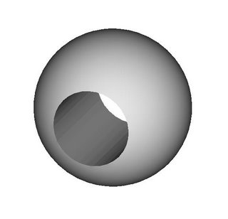
Suppose, for example, you designed a bead like this and it needed to be oriented like this when you were reprapping it.
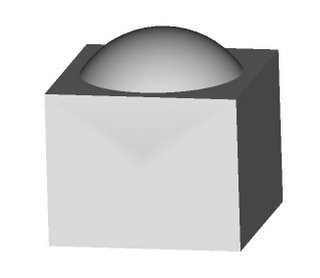
All you'd have to do is envelop it and the cylindrical void in the bead with a rectangular solid like this...
...and then do a boolean operation on the two to remove the bits of the rectangular solid that the bead occupied like this.
This is a snap to do in AoI.
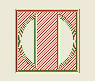
Then you use your handy dandy slicing and dicing software to slice and compute extrusion paths for the support structure...
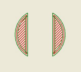
...and then the bead...
{I still have a little code glitch with how the inner perimeters are drawn but you can see how it works anyway.}
...then tag the slice files for the support structure as requiring the polyfil, or whatever, extrusion head and the bead as requiring the CAPA extrusion head.
Merging the two files into one which has the support part and the object part for each layer of the extrusion project should be child's play.
Mind, this may have been something that has already been thought of and Adrian may have had something of the sort in mind all along, but, if it hasn't and/or if he didn't there it is. :-)
Then I think it was yvan roy who said something about using Pov-Ray to do the job which made me remember something that I thought about a long time ago, that is, that it would be neat to leverage the boolean solids operator in AoI to do the slicing and dicing. That would have entailed a major rewrite of AoI, though, a prospect that nobody on the team was excited about doing, much less maintaining after the fact.
Yvan's comment twigged me to thinking about that again and I realised that we ought to be designing the support structure for objects in AoI at the same time we design the object. That doesn't require any rewriting at all.
Suppose, for example, you designed a bead like this and it needed to be oriented like this when you were reprapping it.

All you'd have to do is envelop it and the cylindrical void in the bead with a rectangular solid like this...

...and then do a boolean operation on the two to remove the bits of the rectangular solid that the bead occupied like this.

This is a snap to do in AoI.
Then you use your handy dandy slicing and dicing software to slice and compute extrusion paths for the support structure...

...and then the bead...

{I still have a little code glitch with how the inner perimeters are drawn but you can see how it works anyway.}
...then tag the slice files for the support structure as requiring the polyfil, or whatever, extrusion head and the bead as requiring the CAPA extrusion head.
Merging the two files into one which has the support part and the object part for each layer of the extrusion project should be child's play.
Mind, this may have been something that has already been thought of and Adrian may have had something of the sort in mind all along, but, if it hasn't and/or if he didn't there it is. :-)
Comments:
<< Home
That seems like an awful lot of support structure... and I could see that being very combersom and timeconsuming on complex projects... or I could see giant cubes of support material being prototyped, and causing production times to increase...
I don't see the support structure as being that hard to calculate... so long as you've already got the entire object 'in memory'...
It would be more straightforward in the 'bitmap' scenerio mentioned elsewhere... just make the two bitmaps different colors, lay the bottom one ontop of the top one, and check to see if any of the 'top' one is still visible...
I'm not sure how you're holding the object in memory, but you could essentially render the two layers into a pair of 2 dimensional arrays (x,y coords), search for the empty spots on the bottom layer and compare them to the same location on the top layer...
Overhangs with precision smaller than the extruder head could complicate it a little, but that all depends on how you're rendering the paths, and if the two layers would be the same scale or different...
I think it's better to spend the time to create an elegant software driven solution to this now, instead of having to deal with extra work and clunky blocks of support material... When I'm prototyping objects that need support material, I want to end up with something that looks like a stalagmite... not something that looks like a cube... This is additive manufacturing, and I don't want to have to use more material than I need to...
I would love to look through your code and maybe take a stab at it, but I'm in the middle of a full time C# course, and I can't get distracted by VB.NET, especially with my 5+ years of vb6 experience... I gotta stay focused on C# for now... Once I'm done with class... I'm sure I can figure out VB.NET...
The way I would approach support structure is something along the lines of searching for every polygon where the Z component in the vector was downward facing (an easy test), and include the prisms formed by a plane representing the worksurface into a solid body model.
To calculate the segments for fill, just slice the prism model with a plane, add line segments, and then remove any line segment portion that intersects the actual model.
I am assuming that the build process can generate walls at 90 degrees. If this is not the case, then instead of prisms, some kind of cone structure would need to be constructed instead.
***I would love to look through your code and maybe take a stab at it***
Just yell when you want a copy.
***I can't get distracted by VB.NET, especially with my 5+ years of vb6 experience... I gotta stay focused on C# for now... Once I'm done with class... I'm sure I can figure out VB.NET***
Once you're through C#.NET you'll be acquainted with most of the pathologies of VB.NET. Sadly, the team who put VB.NET together didn't attempt to make VB6 users' transition to VB.NET particularly easy. There are a lot of what are philosophical differences in how VB.NET is structured that cause a lot of trouble for people trying to translate VB6 programmes. Fortunately, I did the transition about two years ago so the pain and annoyance is in the past for me.
Do keep in mind, though, that I'm not a propellerhead as such. Most people who write code for a living just hate the way I write code. I think it has a lot to do with the fact that I started writing code in Fortran 2 back in 1965.
***When I'm prototyping objects that need support material, I want to end up with something that looks like a stalagmite... not something that looks like a cube...***
LOL! The fact that the support block looks like a cube isn't intrinsic to the method. It's a function of the fact that I was grinding out an example to show you all the concept and only took about five minutes to do it. Obviously, for an object that you intended to be made a lot of times you'd want to trim the support volume down to the absolute minimum needed to cut down on built time. AoI lets you do that with no problem.
Post a Comment
LOL! The fact that the support block looks like a cube isn't intrinsic to the method. It's a function of the fact that I was grinding out an example to show you all the concept and only took about five minutes to do it. Obviously, for an object that you intended to be made a lot of times you'd want to trim the support volume down to the absolute minimum needed to cut down on built time. AoI lets you do that with no problem.
<< Home
