Friday, March 17, 2006
Stewart platform, Rev 1.
I've been pretty busy at work, but I have managed to make some progress on the Stewart
platform. Aside from machining the stepper mounts, (2 complete, 4 in progress) I've been modeling up the assembled platform, to get a look at the geometry.
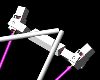
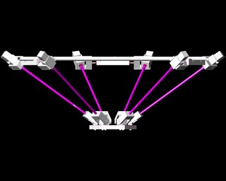
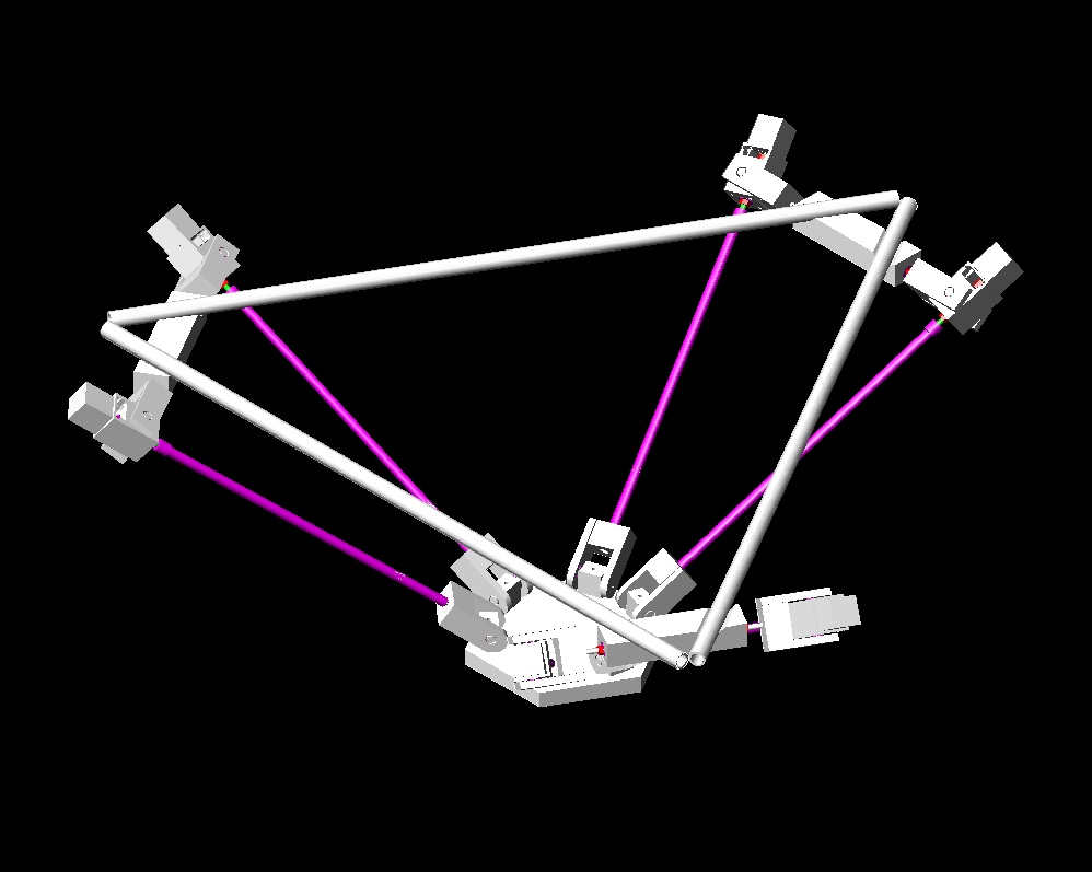
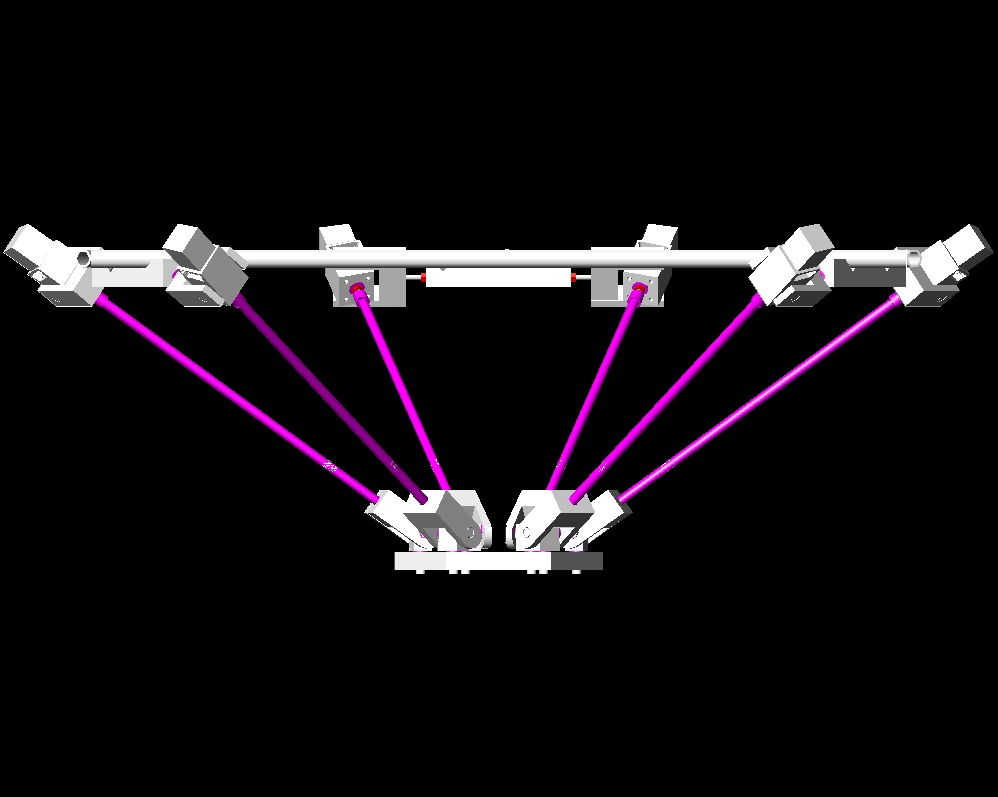
First, an over-view: The frame, (Not all shown) will consist of a space frame with a triangular base and top. Suspended from the top triangle by pipe hangars are blocks which alow lengths of 8m1 threaded rod to freely pivot. At each end of the threaded rod are yokes which suspend the stepper mounts. At the far end of each actuator is a yoke connecting to a pivot attached to the tooling plate.
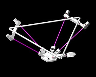
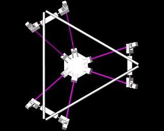
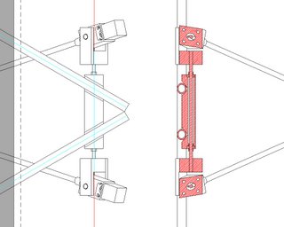
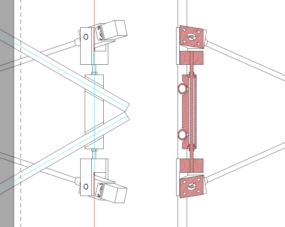
All the pivots are designed to use inline skate bearings, which are fitted around either
8m1 threaded rod, or 8mm shoulder screws.
The yoke designs are still a bit clunky, and I need to model up the extruder to confirm that it will fit, and determine what kind of tilt angles are feasible.
platform. Aside from machining the stepper mounts, (2 complete, 4 in progress) I've been modeling up the assembled platform, to get a look at the geometry.
First, an over-view: The frame, (Not all shown) will consist of a space frame with a triangular base and top. Suspended from the top triangle by pipe hangars are blocks which alow lengths of 8m1 threaded rod to freely pivot. At each end of the threaded rod are yokes which suspend the stepper mounts. At the far end of each actuator is a yoke connecting to a pivot attached to the tooling plate.


All the pivots are designed to use inline skate bearings, which are fitted around either
8m1 threaded rod, or 8mm shoulder screws.
The yoke designs are still a bit clunky, and I need to model up the extruder to confirm that it will fit, and determine what kind of tilt angles are feasible.
Comments:
<< Home
Why is tilt necessary? Why not limit it to 3 DOF? The yokes would be simpler, although then they'd have to handle some torque.

Instead of having exchangable tools, I plan to mount several tools on the head, at different angles, and they can each be brought into play in turn by varying the head angle.
It would certainly be easy enough to flip my mechanism over, and make the tools fixed. Might be worth trying once it's done.
Why not have all the tools at once and use different offsets in the software? Eg mount 4 tools in a 4x4cm square (or whatever) and then add the offset for that tool to the coordinates before activating it?
Suppose I'm working on something larger than 4 cm square? I'd have tools brushing the surface I just deposited. I'd prefer a bit of clearance...
So long as the tools had the same clearance (which I don't see why they wouldn't be, otherwise an actuator would be needed to move them out of the way) then this should be no more of a problem than with a single tool.
Instead of having a single tool in the center of the head, you have four (or more) tools spaced at known offsets around the head. The head still moves, but the final position depends on which tool is currently in use so that it is that tool (not the center of the head) which is over the spot you need to work on.
For example, if the tools are arranged 20mm either side, front and back of the head and the coordinates for a given point have been calculated as x, y.
To use tool 1, x = x-20, y = y-20. Tool 2, x = x+20, y=y-20.
Although the center of the head is now not over the area to work on, moving to these coordinates will position the correct tool over that spot.
Once that start position has been set, the other coordinates are the same relative to that point or keep adding the offsets for absolute coordinates.
Post a Comment
Instead of having a single tool in the center of the head, you have four (or more) tools spaced at known offsets around the head. The head still moves, but the final position depends on which tool is currently in use so that it is that tool (not the center of the head) which is over the spot you need to work on.
For example, if the tools are arranged 20mm either side, front and back of the head and the coordinates for a given point have been calculated as x, y.
To use tool 1, x = x-20, y = y-20. Tool 2, x = x+20, y=y-20.
Although the center of the head is now not over the area to work on, moving to these coordinates will position the correct tool over that spot.
Once that start position has been set, the other coordinates are the same relative to that point or keep adding the offsets for absolute coordinates.
<< Home
![]()