Tuesday, March 14, 2006
Polygon software

When you slice an STL file with a plane, the result is one (or more) polygons. These have to be filled with RP goo somehow to make a solid in layers. As we are going for FDM, this means offsetting the polygon by half the width of the stream, outlining it with goo, then offsetting again and cross-hatching to fill the interior.
I have been writing Java software to do this. I have decided to do a CSG implementation of polygons as unions, intersections, and differences of planar half spaces (i.e. you treat an infinite straight line as being solid on one side and air on the other so, for example, if you intersect three such you make a triangle).
The reason for this is that, compared to the more obvious solution of storing a linked list of line segments between vertex points, once you've got it working it makes polygons that are guaranteed never to self intersect, are easy to offset correctly, and can themselves be easily combined using boolean operations. The downside is that you have to turn the original slice into a CSG form from what is basically an unstructured bunch of line segments that may join up if you're lucky. Fortunately there's an algorithm for that - Tony Woo's alternating sum of volumes algorithm. Implementing that is my next task.
The picture above shows a test polygon, and the result of offsetting it. If you increase the offset, it all behaves nicely, and automatically avoids lines crossing each other:

Cross-hatching for infill is fairly easy. Here's an inner and outer polygon, both offset, then the result cross-hatched:
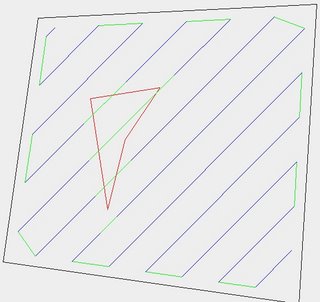
Though I haven't finished that yet - it detects the region in the middle to avoid (different colour), but doesn't link up neatly around it to minimize pen-off-the-paper moves.
How do we do a whole 3D object?
Well, Java3D will read STL files. We slice them from the top down in layers. Imagine that you're at layer N, and the next layer up where you were before is layer N-1. If U is union, - is set difference, PN is the polygon now (at layer N), and PN-1 is the one above, then:
- Get slice PN.
- Fill PN with build material.
- Fill PN-1 - PN with support.
- PN <- PN-1 U PN.
- N <- N + 1.
- If not off the bottom, go to 1.
That defines exactly what needs to happen right the way from the top to the bottom. You work it all out, then play it in reverse from the bottom to the top. This is all particularly simple if U and - are trivial operations, which they are in my implementation. Offsetting is pretty simple too, so things like being able to build slight overhangs without support can easily be accomodated by replacing Step 4. with:
4. PN <- O{(PN-1 U PN), -shrink}
where O{set, distance} is the offset function, and shrink is the width of the overhang that can be sustained.
Job done...
Comments:
<< Home
Your CSG approach reminds me a lot of the methods used in the POV-RAY ray tracing system. If your use of syntax isn't too different, that would mean thousands if not millions of pre-made POVRAY CSG files could be adapted (I restrained myself from qualifying that as "easily") I've got at least a dozen or so I made myself a few years back for some customer's web site images, simulation projects etc. It would be so cool to be able to translate those directly into a matching physical form. It would also mean the converse, you could render some beautifully realistic images in POVRAY prior to actually making the thing. POVRAY is free and supported on most every system out there including Linux so it'd be a good match for those reasons too.
The 3D side is going to be done with Java3D. That'll read STL files and, I suspect, POV-RAY files too. All one will need is a function to cut a plane through a Java3D shape and give back the resulting polygons, either as CSG directly(nice), or as chains of line segments. I'm going to have to handle the latter using Woo's algorithm anyway.
The CSG, incidentally, was all based on the research that John Woodwark (with help from me) did back in the 1980s. He invented almost all the algorithms used in this area.
Has anybody done any thinking about how to generate the shapes of support structures for parts being prototyped?
I know we could do it by hand, but is there anything out there that could automate the process?
Another question I've seen mentioned around here but never seen a clear answer to, how do we get from an .aoi or .obj file format to an STL file that your code can eat?
AoI can export STL files; it's a downloadable module.
As to how we get the support sorted; I've added a bit to the page itself as that's:
1. Important, and
2. Actually quite easy...
As to how we get the support sorted; I've added a bit to the page itself as that's:
1. Important, and
2. Actually quite easy...
On a nearly-related note, Google recently bought SketchUp. If you haven't seen it already, watch the demo video on SketchUp's site. It looks like it's ridiculously easy to create models. Not sure what Google's going to do with it but, given their track record, I'd expect a free version to be released at some point.
POVray is something I'm familiar with - I like CSG - and I've got loads of stuff modelled in it for the aerospace industry. The problem is that the scripts are macros, and do not readily import into anything except POVray.
I've used an adapted version of POVray to do space filling, which allows me to create nanoscale shapes filled in by a molecular lattice. Very handy, but not applicable to what we're doing. Not yet, anyway. I'll get around to building the RepRappable STM some day.
Java 3D has one huge advantage over the things Google seem to put out: It's cross-platform.
Vik :v)
Google's stuff doesn't have to be "cross-platform". Anybody with a browser can access the capabilities.
iqThe methods of stopping line production and head cleaning have been majoritively the same in all implementations that I have done. Basicly, using the natural characteristics of the material, especially the potential for "threading" with glue-gun style materials and devices, is to make more glue sticks. Of course, when one is extruding in 3d, especially with strange hollow spaces, you end up with a LOT of thread remnants while constructing open-cell structures, however, in order to clean most of these, using a conventional laser pointer and a kids microscope (the entire project is childrens' (k-12) classroom fab systems) allows for clearing the threads as well as a form of "case hardening" the surface structure of the open lattice (or surface)... Of course, a lightbulb used the same way is enough to sever the thread and use the same self-constricting physical characteristic as is seen when one burns the end of a hair, to reduce the remnant back to the wall structure. Where does it go?!? This is the primary thing. make yourself more gluesticks, of course, depends on the design of your object, some prefer pellets, others sticks, all the same... the ISSUES: basicly, we know how the materials contract, so, how do you get it AWAY from the high resolution product? well, by constructing a slightly taller TOWER in your open space (regardless of direction, includes suspended spheres or blobs) one can move the head AROUND this tie down and thus generate a very thin (maximal elongation) thread from the start point. Depending on heating element characteristics of your device, or if you use rf or ultrasound heating, one can get very solid cheese-style holes as the remnant of the imprint of your extrusion needle, which just happen to be identical in volume as the thread return. So, you end up with a cast object, central thread collectors, light portals (or just flash the entire model and the threads below a threshold will disappear) and out drops a set of new filler units. Simple stuff. -- we are currently working on a new mass produced fab unit, intended for 10$ range cost, complete with enough to make another unit ... goal is anything from fabrication of fab units for school use to our primary interest, which is remote sensing bots for mapping of parks, cultural places of interest, etc. ... More later, Wilfred Wilfred@Cryogen.com
Lets keep going while im on the topic...
the most effective fill structures in micro scale are usually tilted helix, especially for isoc pyramid structures, giving the most strength to weight ratio for long-distance interconnect supports with these materials.
if one asks "well, if you want to get only the needle hole filled and the rest of the thread remnants to the collector, how?!?" the respons typically includes an explination that when flashed, the material will contract in the direction of its largest volume (diameter), so if you happen to let the threads touch more near the collecction point, they tend to gravitate in that direction (of course, there is some issue with velocity, at which point an alien-spit style glob is generated, especially if the collector rod/etc is intended to be removed from a surface portal, it makes for an eerie looking ejection with ... well... try it ;)
what else... for cnc and fab systems of any type, along with most materials, crystal structures, etc, using 2d slices TENDS TO CAUSE FRACTURE... one can compensate for this by heating the lower level (needle penetration) but it is far more effective to plan helix-style linears rather than lines, the radius of the method dictates the diameter (0+) of the inner space, allowing for both faster printing and layup as well as significantly stronger solidification. As your newest layer's top of the circle meshes with the many-loops-earlier lowest section, you gain 3d structural characteristics that do not exist elsewise... multiple 3d intertwined strands, identical as any most finite resolution, guarantee compatibility materialisticly with any larger scale extrusion, no less offer significant redundency in structure and weight/open space value.
-- Ive done a lot of fluid cooling systems in electronic casting, so being able to case the chips and provide fluid tubes with high resolution redundancy makes for very very fast cooling rates and also provides for dynamic flow rate control (in motive systems) and the related compressor-heat expander techniques similar to your refridgerator... all the same, just think to connect the tubes...
now, for doing this practically, especially in weight critical models, one should consider the mechanical stresses and requirements more than any other, but doing so for solid-style objects, it is likely more effective to lay your helix in very low angle along the length of the edges... without drawing, its basicly the equivalent of stacking discs along the surface with an angle similar to the width of your extrusion... fill it in...
The biggest problem, is when one needs clean surfaces, one can always ambiently heat the solid material, but to finish the surface using an extrusion technique (without other means) you are simply stuck with either best-case nozzle action, or a thread layer, which easily can be flash melted on to the surface... this requires nothing more than suspended threads in a fabric style crosshatch between the outer edges, however, it tends to glob and the selection of tiedown points on the surface is dictated by the exact material and qualities, amongst other things...
so... think NON LINEAR lines as much as possible, however realize that DRAG is a MAJOR problem when doing circles, meaning, for ANY LINE, use cyclic patterns to produce, sure, it will be PI wider on average than your extrusion, but it will at least be constant and dot-based, rather than trying to take a guess on low pricision materials.
so, lines are circles, planars are elongated helix squashed flat, and anything else is likely 3d structures rather than lines, since tying thread on itself is far easier than trying to get it to cooperate linearly.
Let me know how far you want to push the java poly modeling... I am currently working on a modern edu package that has all the documentation, etc along with simulators, control systems, and the ability to produce most anything a class could come up with...
btw, has anyone worked with doping for coloration on a common level? -- we've worked with advanced poly actuators and more chemistry related topics, but the intent is to get the glue to cary a makeup-powder, water color paint, or other particulate material in the process, allowing for 3d scene construction of whatever you modeled or went and imaged...
let me know... -Wilfred
Wilfred@Cryogen.com
AIM/MSN/YP/GM/ETC "WilfredGuerin"
I'll come back and remove this link/post after a day, contact me via email for more info. url has been redirected to a temp at geocities a few mins ago, and has a quick writeup of the new seed curriculum for a k-12 class. new servers and completion of this material should be within a week or two, complete with a new version of all the human interfaces and server code and whatnot, esp with new physics modeling systems in a distributed arrangement...
http://www.Reality3D.Org
I notice p's background in educational programs, and will make sure any other k-12+ curriculum is coherently peered with this new "from-scratch" teaching protocol... we have a heck of a lot of psuedo-unique derivitives and are trying to centralize everything for a new round with stable and proven technique...
-Wilfred
[If this was a forum, this would be a new topic... repost?]
I would first like to make one critical and explicit request:
The documentation has some inconsistancies that I personally think should be globally fixed, especially to allow document-GNU compliance and more specificly the logistic concepts neccessary to recommend RepRap to 3rd parties as a demonstration. Once fixed, the standard of reference and documentation should not be a problem... Here:
http://reprapdoc.voodoo.co.nz/bin/view/Main/RepStrap
The first sentence, if nothing else, should read "ACCESS TO" rather than "OWN" ... it is a simple issue, however the inconsistancies across the documentation and information fluctuate between for-profit concepts versus public-interest (or gnu) release, versus other "its mine pay me" concepts I think inappropriate elsewhere.
In short, one should standardize the conceptual approach in documentation, decide the orientation of the perception, thus dictating the flow models of code logic and documentation similar...
This is a distinct problem for the auditors at many schools, the approval process in many regions (especially where religious vs science issues exist) is quite extreme, auditing every available resource, so any single element misspoken could easily throw access to the entire project for entire school (district or state, etc) regions of kids.
So, lets clean up some documentation and stabilize a standard. I know its not much, but having dealt with such frivilties (as im sure most of you have as well), the resultingly clean logistics and established protocol (with statement of motivations and viewpoint, etc later) would make for significantly less trouble for propogating ideas similar.
Thanks for seriously noting this concern, it is likely the only issue I will have with RepRap, and taking care of the documentation protocol early before there is much more work done on code libraries and publications (lecture materials, etc in my case for a full k-12 class series being overhauled).
Thanks,
-Wilfred
Wilfred@Cryogen.com
AIM/MSN/YP/GM/ETC "WilfredGuerin"
Post a Comment
I would first like to make one critical and explicit request:
The documentation has some inconsistancies that I personally think should be globally fixed, especially to allow document-GNU compliance and more specificly the logistic concepts neccessary to recommend RepRap to 3rd parties as a demonstration. Once fixed, the standard of reference and documentation should not be a problem... Here:
http://reprapdoc.voodoo.co.nz/bin/view/Main/RepStrap
The first sentence, if nothing else, should read "ACCESS TO" rather than "OWN" ... it is a simple issue, however the inconsistancies across the documentation and information fluctuate between for-profit concepts versus public-interest (or gnu) release, versus other "its mine pay me" concepts I think inappropriate elsewhere.
In short, one should standardize the conceptual approach in documentation, decide the orientation of the perception, thus dictating the flow models of code logic and documentation similar...
This is a distinct problem for the auditors at many schools, the approval process in many regions (especially where religious vs science issues exist) is quite extreme, auditing every available resource, so any single element misspoken could easily throw access to the entire project for entire school (district or state, etc) regions of kids.
So, lets clean up some documentation and stabilize a standard. I know its not much, but having dealt with such frivilties (as im sure most of you have as well), the resultingly clean logistics and established protocol (with statement of motivations and viewpoint, etc later) would make for significantly less trouble for propogating ideas similar.
Thanks for seriously noting this concern, it is likely the only issue I will have with RepRap, and taking care of the documentation protocol early before there is much more work done on code libraries and publications (lecture materials, etc in my case for a full k-12 class series being overhauled).
Thanks,
-Wilfred
Wilfred@Cryogen.com
AIM/MSN/YP/GM/ETC "WilfredGuerin"
<< Home