Saturday, March 25, 2006
Godzilla comms board just about done...
I've just about built up Godzilla's comms board. I'd be finished but I bought components for the board quite some time ago and since then Simon discovered that an extra 1 uF electrolytic capacitor was needed to make it work right.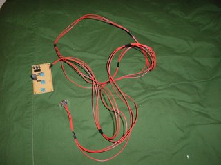
That's all right though. Looking at the extruder controller that Simon and Vik have got rolling now I'm going to need a few extra ! uF electrolytic capacitors for that in any case, so it's off to Potter's in the morning. :-)
I decided to star 5v and 12 v power to each board instead of trying to put power lines in the token ring communications cable. That simplifies the board a bit in that I don't try to convert 12v power into 5v power on the board with a 7805. It also lets me use 2 pin screw terminals instead of the the larger ones on the layouts in the documentation. This board requires only 5v power which is supplied through the screw terminal on the nearest edge of the stripboard in the pic. The incoming and outgoing connections to the token ring are in the middle of the board in the approximate locations shown on the strip board layouts. I spread things out a bit so that I didn't have those electrolytic capacitors bumping into the legs of the MAX232. I also had to move a few jumpers over a few tracks to make room for a bit bigger than usual 100 uF capacitor. Strip board is very nice about letting you get away with that. :-)
Comments:
<< Home
You've noticed one advantage of the MAX202 version of the circuit - ceramic capacitors are less bulky than electrolytics!
I must do a MAX233 version - no capacitors.
Vik :v)
I must do a MAX233 version - no capacitors.
Vik :v)

Other than having to find the proper kind and buy the fool things, the capacitors aren't all that big a bother.
Right now I'm more worried about getting the JavaComms working and writing a test harness to run Godzilla. The link to the JavaComms seems to have disappeared from the Wiki in one of the edits.
Post a Comment
Right now I'm more worried about getting the JavaComms working and writing a test harness to run Godzilla. The link to the JavaComms seems to have disappeared from the Wiki in one of the edits.
<< Home
![]()