Tuesday, February 28, 2006
Charitable thoughts...
There are currently seven researchers and developers working on the RepRap project. Two of them (Ed Sells and Adrian Bowyer) are being paid to do it, and have a research grant to buy materials. The remaining five people are working for nothing in their spare time, and - up until these donations started - were buying all the parts and materials they needed using their own cash.
Now you can help! To make a donation, click on this link:
95% of what you donate will be spent entirely on parts and materials for those five volunteer developers. The remaining 5% goes to SourceForge to thank them.
Monday, February 27, 2006
I♥RP
and then come back after the weekend to find EIGHT real life versions of them waiting for me in the bed of the RP machine...
Sunday, February 26, 2006
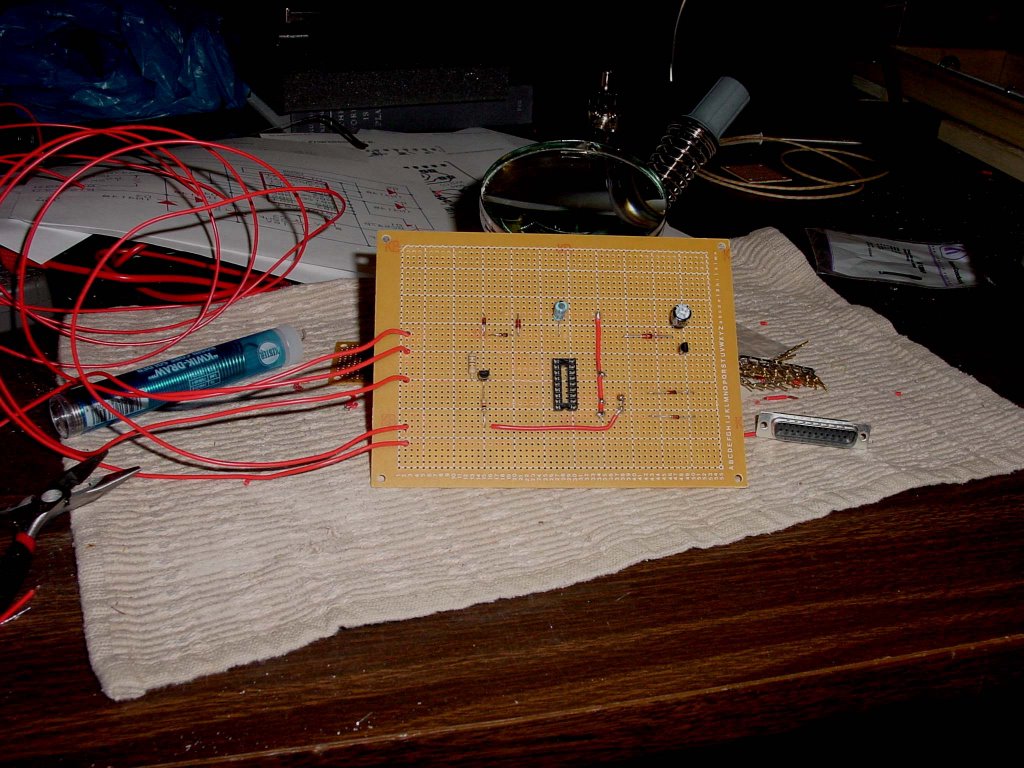
2559 Stepper board prototyped

NOTE: The board in the image above contains several wiring errors.
The UDN2559 driver will put out 700mA per channel and is a more current part (the ULN2803 being on last orders).
Adrian has the latest designs for the Stage Assembly, and when it all works I'll post one down to Simon for his tests - hopefully followed by a second one so he has a complete X-Y axis for software development.
Add to all that the imminent arrival of a donation of CAPA and nichrome samples from Forrest, and I'm going to have a busy week.
Vik :v)
Saturday, February 25, 2006
The twist drill extruder - initial experiments

This is the twist drill extruder (just about) working. Here's a close-up of the polymorph extrudate:
Things I learned:
1. It needs a lot more power for heating. I had three 12 ohm nichrome wires being driven at 12v; i.e. about 36W. It took forever to warm up, eventually reaching a steady-state of about 120oC. But it had to be insulated (or wrapped in paper kitchen towel... kids, if you want to burn down your home, try this - the nichrome gets red-hot where it's in thin air, and sets fire to the paper; see the singed bit where the wires go in in the top picture.) I need to do a re-design heated by a cheap but chunky soldering iron; I think about 100W should do it.
2. The extruder nozzle is 2.5 mm in diameter. This gave an extrusion (with die swell) of 3.15 mm diameter, which is pretty close to what we need.
3. The extrudate has a few bubbles in; more alarmingly, it has pretty flakes of brass/copper swarf. When you turn the drill in air, it doesn't scrape off the sides at all because it's going anti-clockwise. But I suspect the much higher forces involved when the polymer is in there cause it to damage the copper and brass. Thought needed.
Thursday, February 23, 2006
Grinding Frozen Polymorph
1. Polymorph is incredibly tough - the coffee grinder blades make the granules go round and round, but they don't break up, abrade, or indeed change in any way at all, and
2. If you put a whole coffee grinder in a freezer its shaft locks up when the lubricant freezes...
Wednesday, February 22, 2006
Nuff Faff

There's an idler at the end of each angle bracket which winds the timing belt around the frame in a series of N's. They link to the z-bed on the verticals (stays have yet to be added to the table). The X & Y will be added to the top once I've built the Z and am happy that she'll fly.
There's a fair bit of tweaking before I go for a build - the corner brackets will take 6 hours each so it's worth getting it right first time!
Tuesday, February 21, 2006
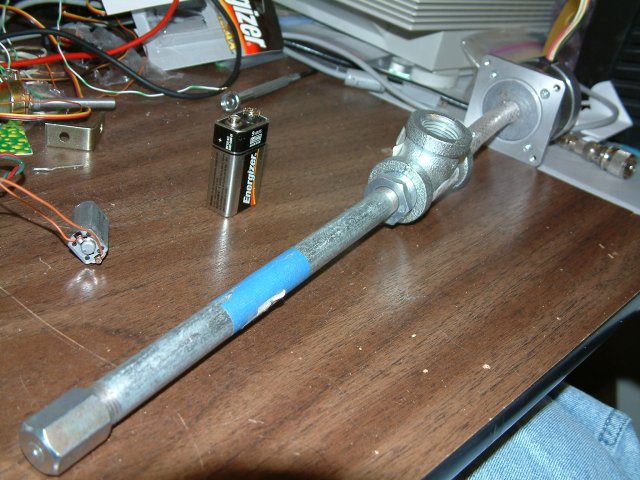
The twist drill extruder

Here's an update on my implementation of Simon and Forrest's idea. It's made from standard 15mm copper and brass plumbing components. The drill bit fits down the middle, being inserted at A. It is rotated anti-clockwise to drag Polymorph in from the feed at B and to drive it into the heated barrel C. D is a thermistor plug for temperature control, and the extruder nozzle is at E.
The design would work with any national standard plumber's compression fittings; all that's needed is that the drill bit (13 mm in mine) is about 0.5mm under the inside diameter of the pipes. The heated barrel uses nichrome heater wire insulated with PTFE tape; that will get a lot simpler when Forrest's insulated nichrome arrives here in Bath.
The thermistor and nozzle can be swapped, and the end cap rotated by 180o. This allows the device to extrude axially or radially, whichever is required.
An obvious improvement would be to use a reduced-shank drill (which I couldn't get quickly) and add another blank plug with a hole for the drill shank at A. That would retain the drill bit nicely in the device against the force to the left from the pressure at the nozzle.
Experiments terminated now owing to a power outage! RepRappers deep in the Waitakere Rainforest who think themselves a little cut off may care to ponder that - in the country that invented electromagnetic induction, and but 30 kilometres from the remains of a civilisation that antedates the pyramids - the bloody electricity company can't keep pumping electrons down the wires in a reliable manner.
Watch this space when the juice resumes...
Pumping CAPA 6800 meal...
I ran the CAPA 6800 meal through the 6.35 mm polymer screw pump. Both the wood and the metal drill bits pumped the meal successfully. Interestingly, the metal bit had a smoother pumping action than the wood. That was probably because it has a closer fit with the pump barrel than the wood auger bit does.
I was able to rotate both wood and metal auger bits with my fingers, which means that the 200:1 gear motor that runs Mk II will run the pump. Whether it will develop the 40 atm head pressure required is another matter. Still, it's a positive sign. :-D
Grinding CAPA 6800
While I was there I asked my brother-in-law if he remembered having an old meat grinder lying around. I recalled seeing one in his shop some time ago. As it happened he has about thirty meat grinders in a storage cabinet. My brother-in-law is an avid collector of antiques of all sorts. I brought home two, a very old Keystone and a not-so-old Universal #2 that looked rather like this.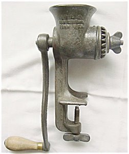
It had a variety of cutting heads which I tried with CAPA 6800 before settling for the one shown in this picture that I found using Google Image search. I would have photographed it and the results of the grinding exercise except that the camera is currently being used on the new quarter horse.
My first mistake with it was to fill the hopper with CAPA 6800. Not! It could comfortably handle about 1-2 grams at a time. CAPA 6800 is incredibly tough. I ran the same 4 grams through about twenty times before being happy with the result. An inclined screen to separate the fully milled polymer from that needing further processing would have been useful. As well a shield to keep a considerable amount of the original pellets from coming out of the cutting face like popcorn would have been useful as well.
The cutting head of the Universal #2 got quite warm even with the very low feed rate that I was using on it.
While I am going to be able to grind feed stock for the 6.35 mm polymer screw pump I don't think that hand grinding is going to be a practical way to prepare polymer for making into filament in the field. We can probably draft an electrical meat grinder into service for the task. Even so, though we are going to have to develop some sort of automated feed mechanism to avoid overloading it and have a vibrating screen as well to segregate the finished meal from polymer needing to be recycled into the grinder again. I suspect that we ought to be able to design something for this part of the system and RepRap it without a lot of trouble. The grinder and screw, however, will have to be steel.
Monday, February 20, 2006
Vik's Presentation As A Stream
http://www.archive.org/details/AucklandLUG_RepRapProject_video
Vik :v)
Sunday, February 19, 2006
Integrating electronics...
Now this may have been discussed one or more times before and if it has I've just reinvented somebody else's approach. Here goes, though. Risk-free thinking.
Put down a layer of polymer with your RepRap.
Now put down a new layer on top of it except where you want your conductor to be. Trade your Mk II extruder head for another Mk II that uses fusible eutetic filament for feedstock instead of polymer filament feedstock. Whether it's Wood's metal, Field's metal or any of half a dozen fusible eutetics is purely a matter of taste and local environmental regulations. Extrude your conducting eutectic into the slot in the second layer. Now here's the fun bit.
Trade back to your polymer extruding Mk II and extrude another layer of polymer on top of all that that leaves the tracks where you want the next layer of conductors to go. Notice that I've turned a corner with the conductor at the right and stubbed it on the left. Although the polymer will melt the conductor when you put it down over the conductor it will float on top since it is a LOT lighter than the conductor. Now trade Mk 2 heads again and fill the new gaps with fusible eutectic.
Trade back to your polymer extruding Mk II and extrude another layer of polymer on top of all that that leaves stubs for the two ends of your conductor. Swap over to your fusible eutectic Mk II and fill the stubs. Viola, you've got your conductor trace with the stub ends such that you can dip a soldering iron dialed down to it's lowest heating level into and stick in your components. Your conductor is completely protected by the polymer except where you need to attach components. Given a very high resolution Mk II extruding head this would be a natural for surface mount IC's and components.
Indeed, later on we might think about incorporating the grab and place features of automated PCB board populators into a very sophisticated RepRap and have it fit the components onto the board as well. :-D
Guys, we could fabricate magnetic coils for motors this way.
Saturday afternoon filament extruder experiments
I ran more experiments today using my 1/4th inch (6.35 mm) ID screw pump. I began with the metal drill bit that I hadn’t used in yesterday’s experiments.
Metal drill bit
Maple syrup
As you recall, water did not pump well at all in the rig.
Semolina grains
I tested the configuration with uncooked semolina grains. The metal drill bit pumped that media wonderfully. I tried putting my fingertip over the end of the barrel. The semolina collected behind my finger and the drill bit was thrust back out of the rear of the barrel with considerable force. A very solid plug of semolina grains were packed in the barrel. I had to literally drill that plug out.
CAPA 6800 pellets.
I fed polymer pellets into the “t” junction. The metal drill bit tended to chop these up and pump them to the end of the barrel. Most, however, of the pellets were thrown back out of the hopper. The pellets that emerged from the barrel were mangled rather than chopped into proper bits.
Visual inspection indicated that the pellets were considerably larger than the helical passage in the metal drill bit. The pellets had to be deformed or chopped until they could be fitted into that passage.
Wood auger bit
I repeated the experiments with semolina grains and polymer pellets. The wood auger afforded a considerably larger passage than the metal drill bit did. Both semolina grains and polymer pellets were pumped effectively. The polymer pellets were not mangled as they had been with the metal drill bit.
Observations
Considerable torque forces are being developed when tough polymer pellets are being cut and mangled. Hanging on to the barrel with a spanner is not practical. A frame holding both the barrel and the drill is needed.
Saturday, February 18, 2006
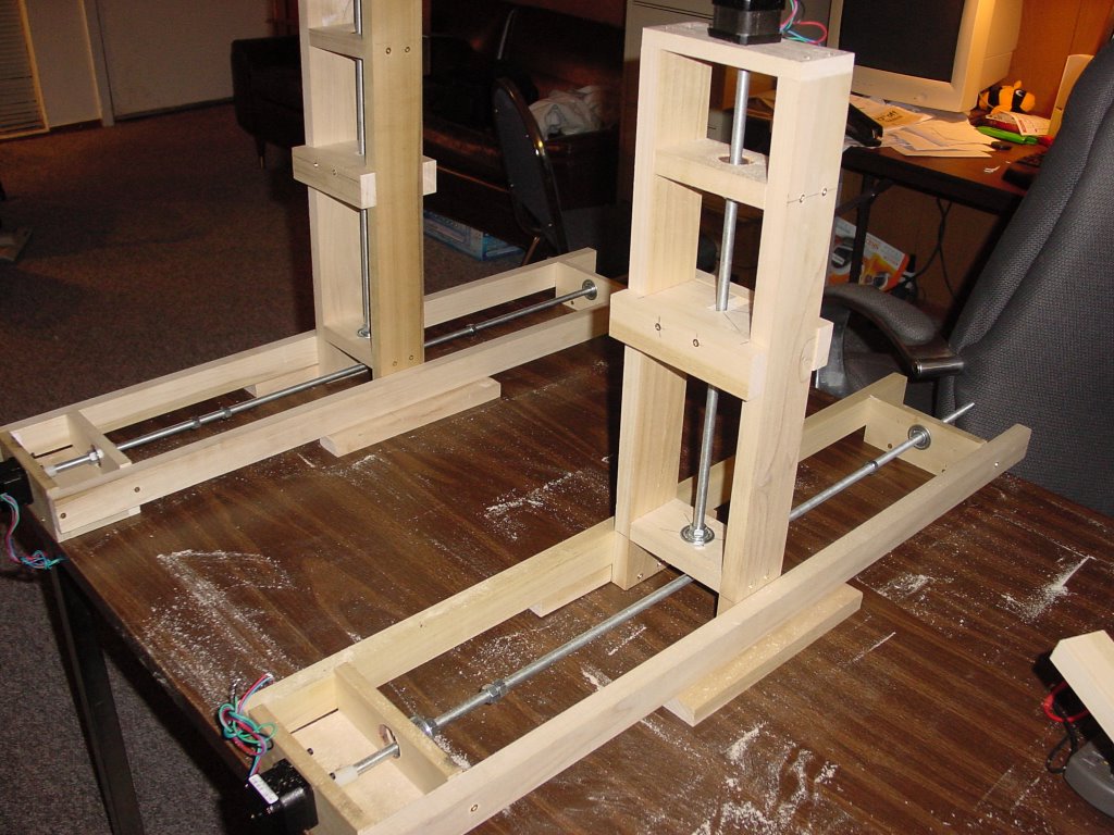
The Concrete Extruder and Full RepRap Axis Assembly

... and some new parts coaxed from the Stratasys by Ed have now enabled the completion of the long linear axis. The holder for the vertical axis now slides nicely up and down the rails, and the vertical axis - to my immense relief - fits in the gaps between the rails and the drive screw properly. The stage sits on top, and the extruder hangs down from above. 'Tis a wondrous sight.

I believe I've pretty much got the hardware I need for a basic RepRap sorted out now. I've got to build 3 of Simon's stepper driver boards, and modify my extruder board but the major hardware work is pretty much done. Here is a picture of the entire X-Y-Z axis collection. All of them have been individually tested and work, but I have only one prototype stepper driver board at present. I want to keep that for basic unit testing, hence Simon's axis boards going into mass production.
I have to modify the stage slightly for Simon so that the new steppers from Forrest will fit properly. I underestimated their size slightly, so I'll have to add mounting lugs in a very ungainly manner. A good job not much torque is needed! Slight downer that I can't find time to play with all the new toys just yet :)
Oh, and my daughter Kate has built one of Simon's stripboard comms controllers with built-in 5V power supply, and it works properly (it's in the front right of the axis image). Now to build something real to get it to communicate with. Lo, I multitask. Kinda.
Vik :v)
Friday, February 17, 2006
The next morning of filament extruder experimentation...
It pumped perfectly. :-)
Reprap Musings
Then, one could create a reprap project that was essentially a scavenger. It roams around, searching for consumables. It would gather enough material to make a copy of itself, then replicate. If done in the correct fashion, it would be an amazingly efficient recycling program. Mouse size robots scurring around, searching for bits that can be recycled, then taking them back to home base. They could use accurate positioning and networking to pinpoint where sources of substrate are, then devour it, ant style.
Since you would only need a finite number of mice to cover a given area, there would undoubtedly be an overstock of workable material. Combine that with the robots being able to recycle most of their parts, it would be very self sustaining. Given the open nature of the project, it wouldn't be hard to imagine a benevolent individual offering free or low cost prints of reprap machines, or any other useful device. That would be very cool.
Obviously, there would be need to be certain guards in place. Ownership of resources would come into play, and also safety of the public. There are currently laws that cover these things. They carry serious punishment if you break them. If your mousebots eat some guys car, he will probably sue you. Likewise, if they eat the actual guy, you will definitely end up behind bars or worse. Even in the extreme event of someone releasing a intentionally malvolent replicating machine, there would be a hundred times as many normal, smart people out there who enjoy not being eaten or killed by robots and could come up with a way to disable it.
Initial experiments on filament extruder 2.0
I built up a rig like the one that Galacticroot did. I used 1/4 inch ID fittings to do it which makes for a much cheaper and more dimunitive pump that Galacticroot had.

Metal bits
The first thing I tried was a 1/4 inch metal bit. I used my electric drill for power and initially tried to pump water with it. You can see it and the barrel that housed it at the top of the picture. The first thing I noticed was that the metal bit pump would not self-prime. I primed the pump and ran it again. At that point I observed that the metal bit would not pump water under any circumstances. Indeed, it seemed to slow down the natural flow of water through the pump. Reversing the rotation of the bit made no difference save that a bit of water began to flow out of the pump at the end closest to the drill and the flow out of the extruder hole pretty much stopped.
At that point I decided that the fit of the drill in the barrel was too loose. I greased the barrel heavily with petroleum grease, reprimed the pump and tried again. There was no useful pumping being done. I observed a tiny bit of pumping in the reverse direction but nothing significant.
Having failed I went back to the literature. The first thing I noticed is that the diagrams I had showed the flight (thread) length on such drawings as I had pretty much identical to the gross diameter of the screw.
 On our 1/4 inch metal drill the flight length was twice (1/2 inch) the diameter. As well, the proportional depth of the threads was much, much larger than what you encountered on a polymer pumping screw. Indeed, there was little core shaft as such in a metal drill.
Wood augers
Next, I tried a wood auger. The flight length of the wood auger was 3/8th inch for the 1/4 inch diameter as opposed to 1/2 inch found in the metal bit. The wood auger was also much longer with many more flights over its length. I acquired a longer barrel and rebuilt the pump. That configuration can be seen in the picture above.
I installed the wood auger, greased the assembly, primed the pump and began again. With the wood auger I got an appreciable pumping action, but nothing useful. Looking more closely at the wood auger it was easy to see that the depth of the flight was proportionally huge compared to a polymer pump screw. There was again almost no core to this auger.
Masonry bits
There are several types of masonry bits. Revisiting the local hardware store I encountered one proportionally almost identical in form to a polymer pump. Sadly, it was 3/16ths inch rather than 1/4. All of the other masonry bits were simple twisted rods and apparently useless.
In the morning I will visit a much larger hardware store and see if I can acquire proper masonry bit to continue the experiments.
Thursday, February 16, 2006
Video of concrete extruder in operation
http://aucklug.debian.co.nz/archive/files/aucklug-2006-02-RepRap.ogg
I can also report that a new batch of FDM'd parts has arrived, and the linear axis no longer contains Meccano components. I've tested all but the vertical axis, which now has new clamps and so forth on it.
More to follow once I get my PC up and running properly.
Vik :v)
PC Death @ Vik
I'll try a reinstall using Ubuntu and see if I can't revive the PC. All files are being copied off onto the server, just in case...
Vik :v)
Saturday, February 11, 2006
PTFE-free extruder well plastered - and extruding
The concrete insulator is still getting greyer and lighter, which bodes well for its insulating properties.
It is undoubtedly harder to manufacture than the PTFE rod version, but uses only readily available materials.
+++ STOP PRESS +++
At the NZLUG meeting last night we hooked up the concrete extruder, set it to 150C and extruded Polymorph with it. It works!
Vik :v)
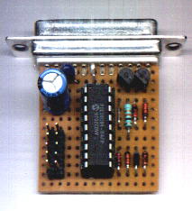
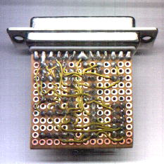
JDM Programmer Card done...
Front Side
Back Side

Cannon connector and cable built

The soldered joints are very strong. I think something might break if I dropped it and stepped on it. Now lets hope I didn't fry anything doing the soldering. :-o
Friday, February 10, 2006
Building the JDM PIC Programmer Card...
The first thing I remembered that I'd forgotten was how poor my fine motor control (neurological not stepper, mind) is. I remembered that when I started fiddling with the tiny little circuit boards that JDM had bought to put the parts to the board on. The mare's nest of wiring on the back side of the board should have been a tipoff, but no. I was still too green.
Fifteen minutes of trying to wrestle parts onto the 45x45 mm board the JDM used sent me back to the supply shop for something more suitable. I conjured that I could just about work with a 115x160 mm board. Perhaps later I will be able to improve on that, but realistically I doubt it.
 Next, I sat down and practiced my soldering technique tacking down the 18 pin socket for the 16F628 chip roughly in the middle of the board. I found that I still remembered how to solder, however poorly.
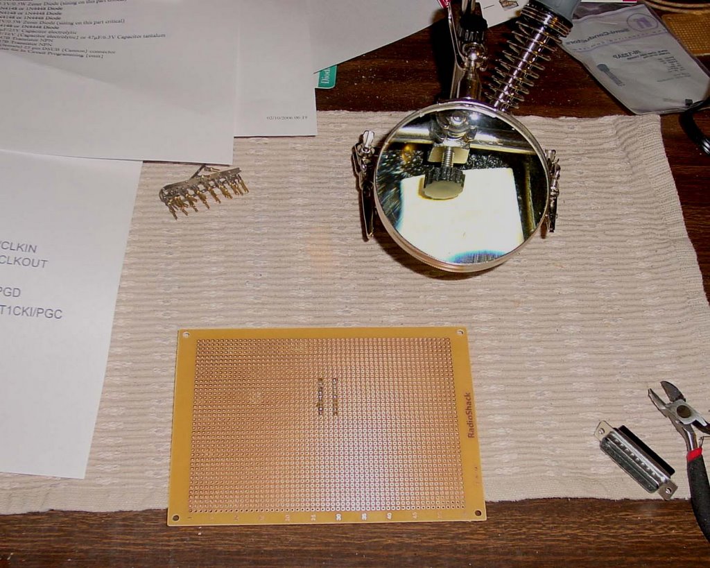
Once finished with that I grabbed a copy of JDM's circuit diagram and started to look at parts to put on the board. Then it hit me, is this circuit diagram looking from the top or bottom of the circuit board? What was the convention? I certainly coundn't remember. The circuit diagram is remarkably unhelpful. No notch mark... no pin 1 note... nothing. That U1 mark at the upper left of the 16F628 might mean pin 1, but it would be nasty to do the whole board and then realise that I had a mirror image of what I actually needed.
Digging around on the Microchip website I found a pic of the chip with the pinouts.

Yup, I was looking at the top of the board. I knew where I was at.
At that point I took the JDM schematic into Photoshop and did a horizontal flip on it so that I could see what the traces would look like from the back of the board.

This must all seem rather ridiculous to you circuitry designer pundits on the team, but I am trying to put myself in the position of about a 14 year old tyro that wanted a Reprap to build action figures that he'd captured out of his favourite video game. Things had to be simple and conceptual leaps had to be very short indeed or we were going to lose such people. For a guy in the Third World, things were likely to be much worse than that. I've taken a few notes from the Gingery DIY books, which have some good ideas on presentation. Even those aren't as well thought-out as they need to be.
You circuit designers have probably already figured out where I am going with this. The component layout on the schematic and the component layout on the board are going to have a one-to-one correspondence. I don't think we can depend on our early adopters having the sorts of topological skills in mentally flipping circuit diagrams that a circuitry designer or even a hobbyist with a few years experience has. Even if all the pieces to a Reprap came in a box with subassemblies already put together this device is not going to be a trivial thing to assemble and get going. I feel that we need to be simpler than possible where ever we can. :-)
Concrete insulator Mk 1

RepRap
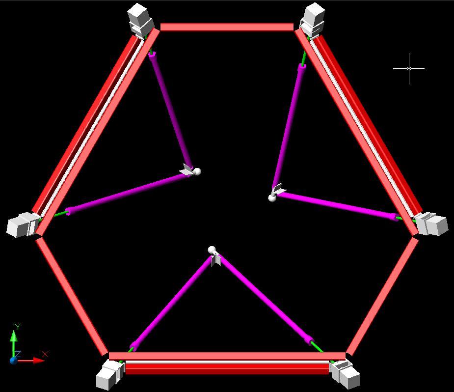
Stewart platform, first stab.
I will revisit this post when the design has been finalized, and try to clean it up a bit. But I felt I ought to make some effort to inform people where this stood.
For the uninitiated, a Stewart platform is a positioning device first used for flight simulators, and today used in some unusual milling machines. Essentially a space frame made of six adjustable length actuators, it's chief virtues are mechanical simplicity, and high rigidity, because all the elements are loaded in tension or compression, rather than bending. A very minimalistic sort of mechanism, without high precision ways or guide rods.
It's chief vice is that control is highly complex and non-intuitive, as a given increment on one axis will produce wildly differing motions in different parts of the platform's range of motion.
Software is, as we all know, cheaper to reproduce than hardware. ;) Hence my belief that the Stewart platform is better suited to reprap than cartesian positioning systems.
My primary objective these last few days has been to design a really cheap, yet backlash free, linear actuator, which can be used in the construction of such a platform. The main components I have settled on are 8M1 threaded rod, and 1/4" schedule 40 steel pipe. I have determined that it is possible to press a standard bronze bushing into the end of such pipe, and tap it for 8M1 thread, producing a nut with much less friction and slop than one would obtain from a hardware store. Said nut can be retained nicely by simply screwing onto the end of the pipe a pipe cap which has had a clearance hole drilled in it.
It is a glad coincidence that the inline skatewheel bearings plaasjaapie pointed out to us have a bore of 8 mm, and an outside diameter of 22 mm, the same as the pilot on a NEMA 17 stepper motor, such as he has also brought to our attention. This will make maintaining concentricity between the stepper shaft and threaded rod comparatively simple even without precision machining.
The stepper shaft and threaded rod can be mated by the simple expedient of turning the end of the threaded rod down to the same diameter as the stepper shaft, give or take a fraction, and pressing them into opposite ends of a short piece of tubing. A technique I can claim no credit for, I saw it used in Battlebot drive trains.
Geometry
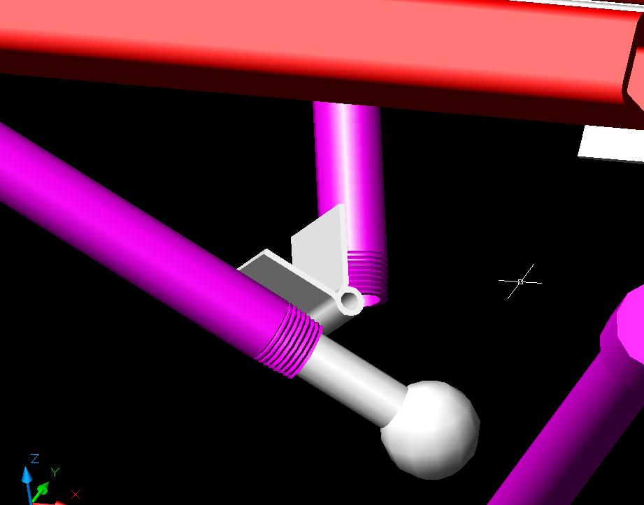
There are a number of varients on the Stewart platform. The one I have chosen as easiest to implement has the actuators paired up, forming three triangles, each of which has one vertex connected universally to the tool head. The advantages of this are that universal joints are minimized, and screw torque can be expediently dealt with. Note that there is no tool head in the illustration below; I have not yet modeled that part. I plan to finish up the design this Saturday.
 Because the actuators in a given pair remain co-planar, they can be connected to each other, and to the fixed member between them, by simple hinge joints. Then that member can be connected to the common frame by another hinge. The only universal joints needed are between the common vertex of the actuator pair, and the tool head. It is my intent to use an industry standard tooling ball inserted into the end of one of the pipes, trapped within a tool head composed of a plastic sandwich, in order to form the universal joints. These are manufactured to high precision, and are available cheaply by mail order.
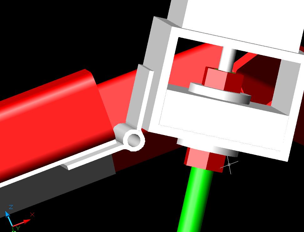

Calibration.
Calibration is a nightmare with this beast. Essentially, it will be necessary to include a CMM mode, during which the platform will feel various objects of known dimension, and derive from it's findings a mathematical model of it's own geometry. Using math I haven't needed to call on since college a quarter century ago. ;)
Multiple functions.
Since the Stewart platform is inherently six axis, it ought to be possible to mount several mechanisms on the tool head, and bring each to bear in turn by tilting the head at different angles. Or if desired, to add materials to the sides of an object being built, instead of just it's top surface.
RepRap
Thursday, February 09, 2006
String Wars
 String, I quickly learned, is rubbish. It suffers from creep under the high pre-tension required for the rig to work. After doing lots of hunting [big thanks to previous inspired comments] I hit the jack pot with high tensile steel fishing wire coated with nylon. Cheap & accessible - ideal reprapability.
A big problem with wire is its grip on the drive wheel grip. The figure below (left) shows the simplest drive wheel setup. Shrink wrap on the drive wheel certainly helped things, but with such thin transmission wire and a small (ø 12 mm) drive wheel to achieve high resolution (specifically without gears) the total grip was naff all. I tried a pinch assembly to increase the contact angle but that wasn’t enough either.

And so the wire was wrapped at least once around the drive wheel. It solved the grip problem, but because it was wrapped it followed the Archimedes screw principle and rode up and down the length of the wheel when it was turned: bad news for repeatability and accuracy I thought, not to mention messing up the tensions.
I tried everything I could to stop the wrap from riding, from shelves and curves on the drive wheel to constraint on the input & output. Absolutely nowt. The wrap will always ride. I went snowboarding, and reminisced about the pint I’ll never have whilst being mocked by chairlifts which are mostly made out of wire, pulleys and drive wheels.
But I got back and thought “well lets let the wrap ride then”. What are the accuracies and repeatabilities like? Answer: Good. For the 10cm distance I could test it seemed repeatable (triple wrapped on a plain shrink wrapped drive wheel). There’s some mysterious jamming going on in my rig with an asymmetrical load (to be fixed with better bearing constraint), but when I put a timing belt on it, this made no difference and proved my wire’s innocence.
The worry I have with the wrap unbalancing the tension is because as soon as it moves above or below the centre plane of the drive wheel it creates a larger hypotenuse = strain = increase in tension. See below…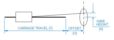
But I did some calcs & worked out an egg shaped profile for the drive wheel which would side step this problem. The graph below shows the dimensions of the profile which I think is doable (for an offset of 100 mm, pitch 0.5 mm & max carriage travel of 300 mm).
So Adrian will certainly get the pint, but wire is not yet dead: it is the rebel faction in my transmission war and although I’ll be working with teeth for ARNIE Mk 1, I’ll be thinking of string.
Wednesday, February 08, 2006
Mk 2 parts arrive
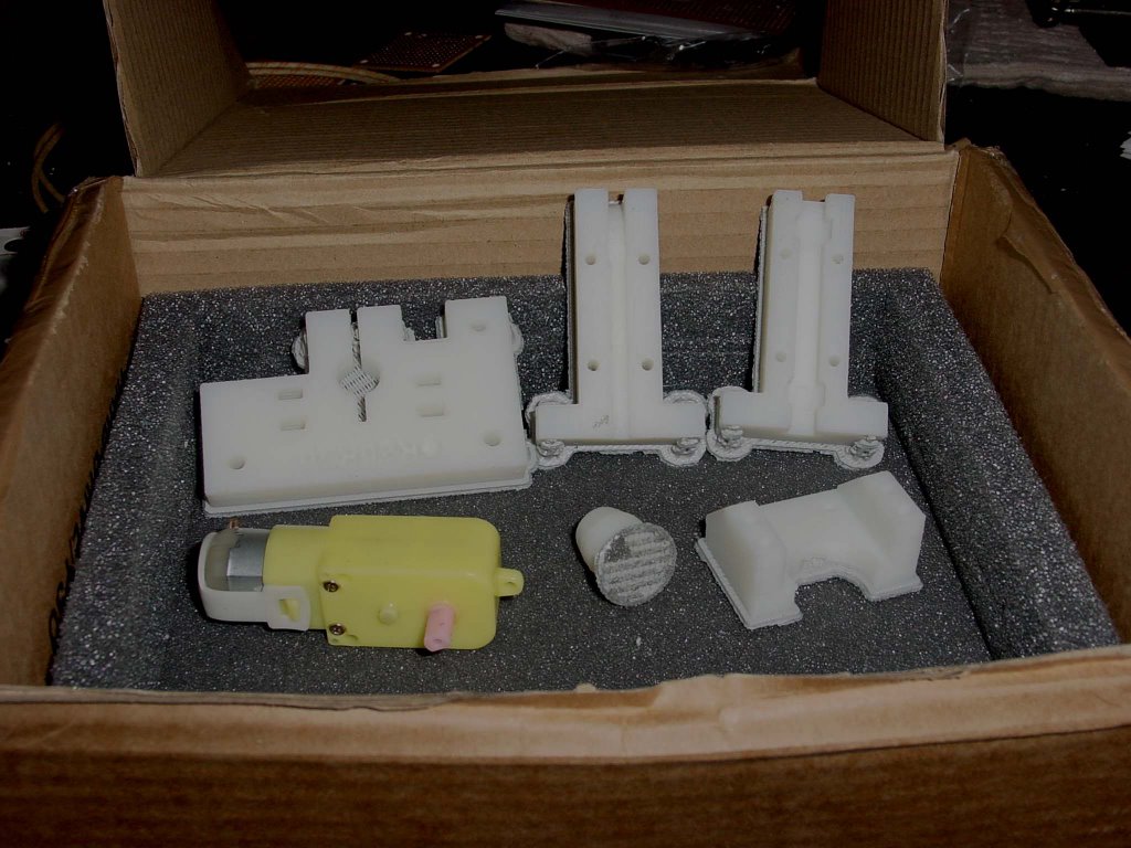
I'd measured the Mk 2 from the photos half a dozen times. Until I held the parts in my hands I hadn't been able to get my head around the idea that this is a tiny thing. It's brilliant! :-)
Tuesday, February 07, 2006
First concrete test cylinder
The concrete had a great many voids in it, and some of this may need removing. Perhaps a sander or similar vibration system could settle the concrete more thoroughly?
The screw embedded in the concrete comfortably supports a 12N load. A firm, steady pull just using fingers failed to dislodge the screw.
The central 3mm hole had rough sides, but was well-formed with little debris.
A 52mm I/D test article strengthened with fine zinc-plated steel wire awaits concrete pouring. I've fitted the heater barrel into the bottom of the mould by mounting it on a tin lid and taping it to the end. I need to make a couple of M3 anchors for it and we're ready to roll.
Right now it's dark and I'm tired. G'night.
Vik :v)
Godzilla is done for now...
I got to a stopping point after a 3 hour push this morning and another 3 hour push late this afternoon.
I was getting a bit punchy so I ran the movie Dogma for distraction for the last two hours of work. It suited my mood. Before that I had uninstalled Photoshop thinking it was Acrobat. Acrobat has been giving me fits for some reason.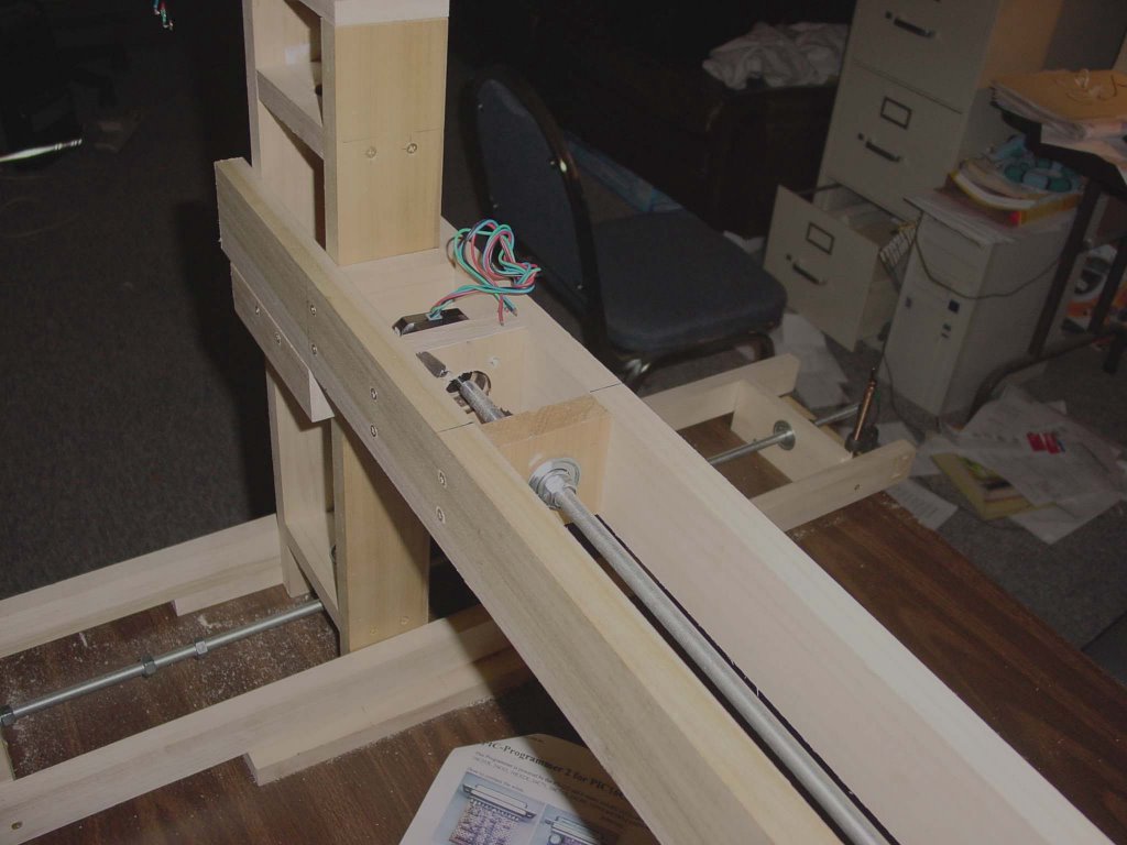
The X-axis stage is a bit fiddly. I wanted to keep it relatively narrow and centered on the Y-axis threaded rods(the y-axis threaded rods are also centred on the z-axis threaded rods). I've tried to reduce the eccentricity of loading to the bare minimum. When I do that I use less materials trying to brace against eccentric loads. As a result it is a bit hard to work with.
You can see a mockup of the stage on which I will be able to mount the Mk 2 extruder in the centre of the x-axis.
The usuable working volume is measured now at 700x700x350 mm.
Now to build that PIC programmer board. :-)
Monday, February 06, 2006
Second z-y stage built
 I may do that later on.
The y stage towers move easily with a touch of the finger. There was much less friction in the system than I had thought. Of course, the acid test will be when I load the x-axis onto those towers. I've calculated that loading to be no more than about 3 kg split two ways between the towers so it should not be terrible.
I did make one small mistake on the second one though. I took a centre measurement to be a top end measurement on the top bearing plate.
 It will only take about 10 minutes to shift that upwards, but I'm not going to fix that tonight.
In the last pic I've mocked up the x-axis so that you can get a feel for the overall size of godzilla. It got considerably wider when I decided that it would be best to keep the x-axis threaded rod on the centre-line between the two towers. That meant that I had to handle the full 36" of the rod plus the connector plus the stepper. Oh well, I didn't really want to throw any dinner parties this year. :-)
I c-clamped the beams onto the towers and checked the resistance to movement. It's more substantial than before, but still no big strain from a purely qualitative standpoint.
Sunday, February 05, 2006
Progress with cement
To insulate the barrel, I'm planning on using BBQ paint. This is a commonly available ceramic-filled paint based on high-temperature polyesters and is good up to 630C. The windings will be held down with plaster and fibreglass. There is a page on the Wiki covering the experimentation:
http://reprapdoc.voodoo.co.nz/bin/view/Main/HighTemperatureMaterials
Concrete and BBQ paint take some time to cure, however, so the results will take a few days to come through.
Vik :v)
Saturday, February 04, 2006
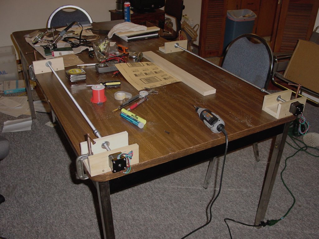
Moving right along...
As I mentioned last time, I had problems with the threaded rod not being quite straight. I sorted out 95% of that by straightening the rod, but finally decided that I needed some guideways to damp out as much of the wobble in the system as possible. Rather than going for steel rods I decided to just use more poplar. Oh yes, hereafter I am going to use AoI coordinate naming conventions.
Here is the z-axis with guide rails.
 I have positioned them above the working surface {x-y} so that they can provide for stability not only against rotation around the z-axis, but also the x and y axes.
Here is the y-axis positioner.
 Note the rails inhibiting rotation around the x-axis.
Now you can see the two integrated.

The y-axis slides back and forth in the z direction like a drawer.
What is not shown yet is the positioning collar for the y-axis that supports the x-axis positioning stage. I want the x-axis stage to fit around and slide down over the y-axis like a collar so that there is as as little eccentric loading of the system as possible.
Of course, there are two z-y assemblies like this that support the x-axis stage between them like a beam. I will pin connect the x-axis stage to one of the y-stages and use a sliding joint for the other so that we do not transfer any torques from one of the z-y assemblies to the other.
So far the system is modular and pretty much demountable. I am currently working out how to keep that demountability happening in the collar on the y-axis that supports the x-axis stage. I think I have a way, but I will have to purchase a few long bolts and wing nuts to make it happen. So it goes.
Here is the combined z-y axes stages with the bracket for supporting the x-axis stage in place.

The system is also scaleable. Using American parts and increasing the diameter of the threaded rod I can easily push the x-axis out to 1800 mm. Do., the z-axis. The y-axis stage is a little trickier, though.
Thursday, February 02, 2006
Replacing PTFE with concrete
It's not very good under tension though, and needs to be kept moist during the curing process - small amounts of concrete are notoriously difficult to cure. I suspect a dampened ,sturdy cardboard tube may be a good former.
Assembling the brass nozzle into a cement holder should be easy enough - either directly or by adding a couple of nuts to it so it can be removed for maintenance. End plugs left as an exercise to the dilligent researcher (Polymorph, gaffer tape, whatever...)
I'm considering putting M3 thread or long bolts down the full length of the cylinder, and making the cylinder roughly 30mm in diameter, 60mm high. I'd be surprised if a 12W heater could warm the entire thing.
The protruding M3 thread would be useful in attaching the holder to the extrusion mechanism, dispensing with the current clamp entirely.
I also wonder if embedding fibreglass insulation would increase the strength of the concrete in tension? It wouldn't help with insulation obviously.
Another tack might be to embed perlite or vermiculite in the concrete to reduce its thermal conductivity.
I feel messy experimentation coming on...
Vik :v)
Wednesday, February 01, 2006
X-axis done...
I decided that I was going to make it of aluminum, which is, pound for pound, cheaper to use than steel. This would entail learning how to braise aluminum joints but that, technically, was not daunting. Doing the job seemed to be wanting to cost about US$450-500 by the time all the parts were bought. Once those numbers were on the spreadsheet the whole exercise began to look vaguely ludicrous, never mind high risk.
While the AoI simulations revealed a lot of volumetric problems with putting the pieces together. It did nothing to reveal the sorts of problem that the pieces themselves might cause. Until I knew those sorts of answers the risk involved in going for an end product was simply too high to contemplate.
Instead, I've opted for a minimalist approach that borrows from Simon's RepStrap concept. For a working material I've chosen poplar wood. It comes in sizes that are very close to what I was using in the AoI design exercises. It is easy to work with inexpensive tools and, above all, it is so cheap that if I make a mistake I can just throw that bit it away and not rue the expense especially.
 Godzilla depends on pairs of parallel power screws. I had web surfed enough companies doing precision positioning systems to know that parallel anything is a rather tricky condition to achieve. Because of that I opted to just c-clamp modules down to a relatively flat surface, viz, my work table. That got me to the next problem.
Threaded rods of the sort that you can buy from a hardware store are only sort of straight until you get up to diameters of 12 mm or so. At 3/8" inch (roughly 8 mm) you can get fine threads and a good price, but you also have troubles with straightness. Remembering an old Lindsay publication that showed how WWI-era British artisans hand straightened Enfield rifle barrels used the same tricks and got the two I had bought reasonably straight (about 1 mm play or less).
I drilled out a nylon sleeve to make the coupling mockup between the power screw and the stepper. It is already obvious that that is not going to be a satisfactory solution with a fixed mount stepper. You get just a bit of play and that will wear out the stepper bearings pretty quickly. I have got to either put the drive rod and stepper in orthagonally separate sliding mounts or create a drive coupling that damps out that kind of play.
The pair of x-axis screws will push and pull a derrick containing the y and z axes back and forth across the table. The power screws will be attached to the derrick with sliding joints allowing for freedom of movement in the z-axis. Later I can cover the table with extremely flat float glass thick enough to not respond to unevennesses in the table. As it stands, though, the present rig will create a complex lateral movement profile in the y direction.
Obviously, if I had straight, stiff theaded rods I would not have a problem. Indeed, there is a little company that manufactures power screws situated about 150 km down the coast that will make me very straight power screws for US$/20 per foot. That would solve the problem but break the budget yet again.
I could also supplement the x-axis stage with guide rods to take up the y-axis play. That begs the question of where one gets straight guide rods and at what price. I can go for diameter and add a lot of weight and cost, or go for tool steel drill rods and add cost... or I can see if the y-axis play is repeatable and can be mapped. My tendency is to go for mapping.
I had originally though to map the system using a seperate head that was the same as the extruder but with a microswitch on the extruder end. While Adrian recently suggested using some sort of lumpy standard, I thought that using a tilted piece of glass in the work space ought to give us the information we need.
Adrian recently put down the reliability of microswitches to guard the ends of the axes. I gathered by implication that some sort of optical sensor would be better. I wonder how we could sense contact or proximity to a calibration surface if we do not use a microswitch?
![]()