Friday, February 10, 2006
RepRap
Stewart platform, first stab.
I will revisit this post when the design has been finalized, and try to clean it up a bit. But I felt I ought to make some effort to inform people where this stood.
For the uninitiated, a Stewart platform is a positioning device first used for flight simulators, and today used in some unusual milling machines. Essentially a space frame made of six adjustable length actuators, it's chief virtues are mechanical simplicity, and high rigidity, because all the elements are loaded in tension or compression, rather than bending. A very minimalistic sort of mechanism, without high precision ways or guide rods.
It's chief vice is that control is highly complex and non-intuitive, as a given increment on one axis will produce wildly differing motions in different parts of the platform's range of motion.
Software is, as we all know, cheaper to reproduce than hardware. ;) Hence my belief that the Stewart platform is better suited to reprap than cartesian positioning systems.
My primary objective these last few days has been to design a really cheap, yet backlash free, linear actuator, which can be used in the construction of such a platform. The main components I have settled on are 8M1 threaded rod, and 1/4" schedule 40 steel pipe. I have determined that it is possible to press a standard bronze bushing into the end of such pipe, and tap it for 8M1 thread, producing a nut with much less friction and slop than one would obtain from a hardware store. Said nut can be retained nicely by simply screwing onto the end of the pipe a pipe cap which has had a clearance hole drilled in it.
It is a glad coincidence that the inline skatewheel bearings plaasjaapie pointed out to us have a bore of 8 mm, and an outside diameter of 22 mm, the same as the pilot on a NEMA 17 stepper motor, such as he has also brought to our attention. This will make maintaining concentricity between the stepper shaft and threaded rod comparatively simple even without precision machining.
The stepper shaft and threaded rod can be mated by the simple expedient of turning the end of the threaded rod down to the same diameter as the stepper shaft, give or take a fraction, and pressing them into opposite ends of a short piece of tubing. A technique I can claim no credit for, I saw it used in Battlebot drive trains.
Geometry
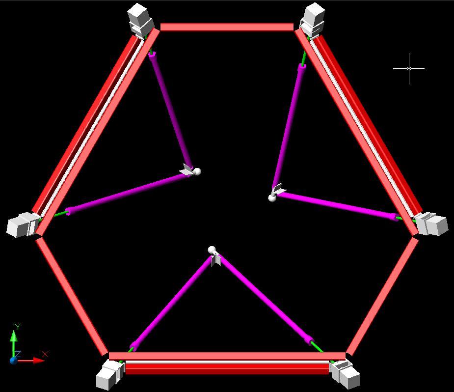
There are a number of varients on the Stewart platform. The one I have chosen as easiest to implement has the actuators paired up, forming three triangles, each of which has one vertex connected universally to the tool head. The advantages of this are that universal joints are minimized, and screw torque can be expediently dealt with. Note that there is no tool head in the illustration below; I have not yet modeled that part. I plan to finish up the design this Saturday.
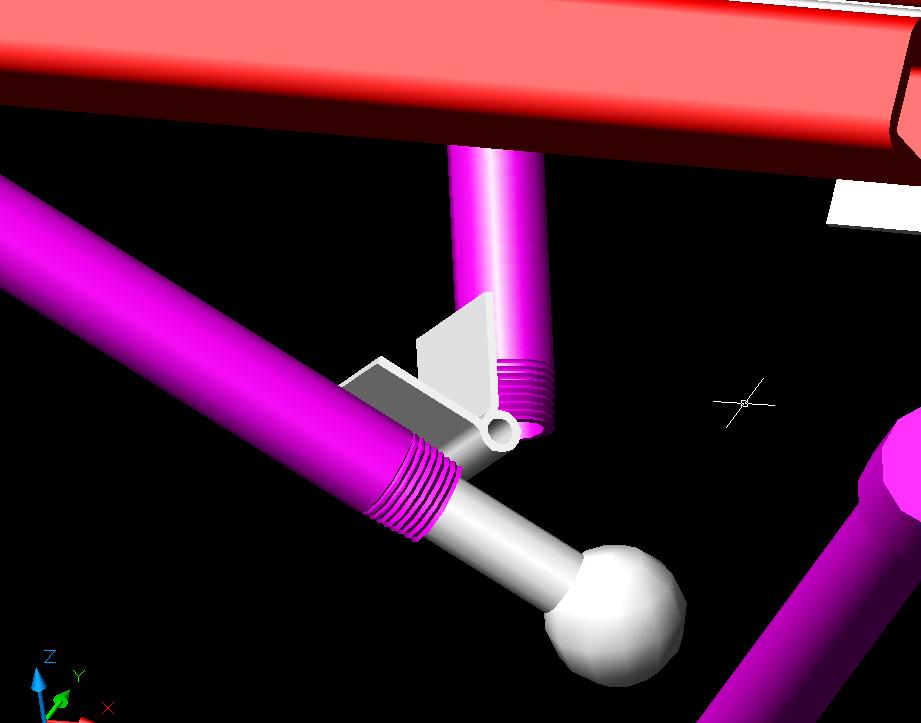
 Because the actuators in a given pair remain co-planar, they can be connected to each other, and to the fixed member between them, by simple hinge joints. Then that member can be connected to the common frame by another hinge. The only universal joints needed are between the common vertex of the actuator pair, and the tool head. It is my intent to use an industry standard tooling ball inserted into the end of one of the pipes, trapped within a tool head composed of a plastic sandwich, in order to form the universal joints. These are manufactured to high precision, and are available cheaply by mail order.
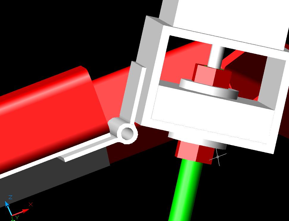

Calibration.
Calibration is a nightmare with this beast. Essentially, it will be necessary to include a CMM mode, during which the platform will feel various objects of known dimension, and derive from it's findings a mathematical model of it's own geometry. Using math I haven't needed to call on since college a quarter century ago. ;)
Multiple functions.
Since the Stewart platform is inherently six axis, it ought to be possible to mount several mechanisms on the tool head, and bring each to bear in turn by tilting the head at different angles. Or if desired, to add materials to the sides of an object being built, instead of just it's top surface.
RepRap
Comments:
<< Home
Looks great so far, Brett! I really wanted to do a Stewart but didn't have the nerve or the shop. You've got both. :-)

Ah, kinematic callibration. Best of luck!
http://mmc.me.kyoto-u.ac.jp/research/para/ishida/pa_ishida.html
Vik :v)
http://mmc.me.kyoto-u.ac.jp/research/para/ishida/pa_ishida.html
Vik :v)
Cool! Looks like hard core maths, but like you say that's light. Do the tools go on the red hexagon or is that the bed? & what's its maximum reach angle, or probably better put: how acute can the tools be brought in from the side?
Ed:
The red hexagon is a partial frame to which the actuators are attached. The tools will go on a head which hangs below that frame, (I'm thinking that at low speeds, the actuators can be kept purely in tension, eliminating backlash.) and which has not been modeled yet. The base on which material is deposited is still lower.
Until I've finished modeling the head, I can't really determine the angular limits of head travel in various places, because that will be established by interference between the actuators and the extruder. Even then a hairy task, because the geometry of the thing makes it very difficult to draw.
Sure, I could put the extruder entirely below the acuator mounts, and eliminate that issue, but the further the deposition point is from the plane of the universal joints attaching the actuators to the head, the more sensitive it's position is to small actuator motions.
Vik:
Hey, nice link! Been a while since I'd seen anybody using that calibration method, I'd forgotten about it. My plan had been to cmm some 123 blocks.
Have you seen this? I think it will come in handy: http://robofac.sourceforge.net/index.html
Plaasjaapie:
I don't know about nerve, but as to the shop, in keeping with what I take to the be spirit of this project, I'm avoiding use of it as much as possible. My goal has been to come up with a Stewart platform you *don't* need a shop to build.
Post a Comment
The red hexagon is a partial frame to which the actuators are attached. The tools will go on a head which hangs below that frame, (I'm thinking that at low speeds, the actuators can be kept purely in tension, eliminating backlash.) and which has not been modeled yet. The base on which material is deposited is still lower.
Until I've finished modeling the head, I can't really determine the angular limits of head travel in various places, because that will be established by interference between the actuators and the extruder. Even then a hairy task, because the geometry of the thing makes it very difficult to draw.
Sure, I could put the extruder entirely below the acuator mounts, and eliminate that issue, but the further the deposition point is from the plane of the universal joints attaching the actuators to the head, the more sensitive it's position is to small actuator motions.
Vik:
Hey, nice link! Been a while since I'd seen anybody using that calibration method, I'd forgotten about it. My plan had been to cmm some 123 blocks.
Have you seen this? I think it will come in handy: http://robofac.sourceforge.net/index.html
Plaasjaapie:
I don't know about nerve, but as to the shop, in keeping with what I take to the be spirit of this project, I'm avoiding use of it as much as possible. My goal has been to come up with a Stewart platform you *don't* need a shop to build.
<< Home
![]()