Wednesday, February 01, 2006
X-axis done...
After the NEMA 17 steppers arrived the obvious question was "now what do I do?" I spent a while doing a detailed design development of the last iteration of the Godzilla design.

I decided that I was going to make it of aluminum, which is, pound for pound, cheaper to use than steel. This would entail learning how to braise aluminum joints but that, technically, was not daunting. Doing the job seemed to be wanting to cost about US$450-500 by the time all the parts were bought. Once those numbers were on the spreadsheet the whole exercise began to look vaguely ludicrous, never mind high risk.
While the AoI simulations revealed a lot of volumetric problems with putting the pieces together. It did nothing to reveal the sorts of problem that the pieces themselves might cause. Until I knew those sorts of answers the risk involved in going for an end product was simply too high to contemplate.
Instead, I've opted for a minimalist approach that borrows from Simon's RepStrap concept. For a working material I've chosen poplar wood. It comes in sizes that are very close to what I was using in the AoI design exercises. It is easy to work with inexpensive tools and, above all, it is so cheap that if I make a mistake I can just throw that bit it away and not rue the expense especially.
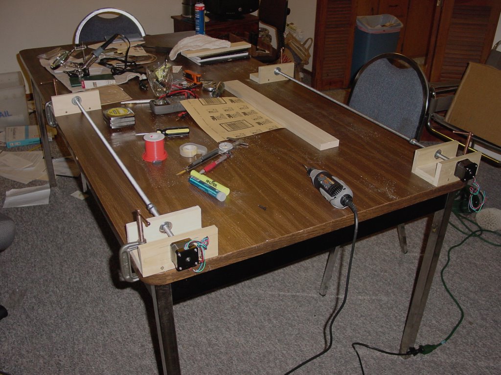
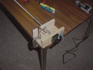 Godzilla depends on pairs of parallel power screws. I had web surfed enough companies doing precision positioning systems to know that parallel anything is a rather tricky condition to achieve. Because of that I opted to just c-clamp modules down to a relatively flat surface, viz, my work table. That got me to the next problem.
Threaded rods of the sort that you can buy from a hardware store are only sort of straight until you get up to diameters of 12 mm or so. At 3/8" inch (roughly 8 mm) you can get fine threads and a good price, but you also have troubles with straightness. Remembering an old Lindsay publication that showed how WWI-era British artisans hand straightened Enfield rifle barrels used the same tricks and got the two I had bought reasonably straight (about 1 mm play or less).
I drilled out a nylon sleeve to make the coupling mockup between the power screw and the stepper. It is already obvious that that is not going to be a satisfactory solution with a fixed mount stepper. You get just a bit of play and that will wear out the stepper bearings pretty quickly. I have got to either put the drive rod and stepper in orthagonally separate sliding mounts or create a drive coupling that damps out that kind of play.
The pair of x-axis screws will push and pull a derrick containing the y and z axes back and forth across the table. The power screws will be attached to the derrick with sliding joints allowing for freedom of movement in the z-axis. Later I can cover the table with extremely flat float glass thick enough to not respond to unevennesses in the table. As it stands, though, the present rig will create a complex lateral movement profile in the y direction.
Obviously, if I had straight, stiff theaded rods I would not have a problem. Indeed, there is a little company that manufactures power screws situated about 150 km down the coast that will make me very straight power screws for US$/20 per foot. That would solve the problem but break the budget yet again.
I could also supplement the x-axis stage with guide rods to take up the y-axis play. That begs the question of where one gets straight guide rods and at what price. I can go for diameter and add a lot of weight and cost, or go for tool steel drill rods and add cost... or I can see if the y-axis play is repeatable and can be mapped. My tendency is to go for mapping.
I had originally though to map the system using a seperate head that was the same as the extruder but with a microswitch on the extruder end. While Adrian recently suggested using some sort of lumpy standard, I thought that using a tilted piece of glass in the work space ought to give us the information we need.
Adrian recently put down the reliability of microswitches to guard the ends of the axes. I gathered by implication that some sort of optical sensor would be better. I wonder how we could sense contact or proximity to a calibration surface if we do not use a microswitch?
I decided that I was going to make it of aluminum, which is, pound for pound, cheaper to use than steel. This would entail learning how to braise aluminum joints but that, technically, was not daunting. Doing the job seemed to be wanting to cost about US$450-500 by the time all the parts were bought. Once those numbers were on the spreadsheet the whole exercise began to look vaguely ludicrous, never mind high risk.
While the AoI simulations revealed a lot of volumetric problems with putting the pieces together. It did nothing to reveal the sorts of problem that the pieces themselves might cause. Until I knew those sorts of answers the risk involved in going for an end product was simply too high to contemplate.
Instead, I've opted for a minimalist approach that borrows from Simon's RepStrap concept. For a working material I've chosen poplar wood. It comes in sizes that are very close to what I was using in the AoI design exercises. It is easy to work with inexpensive tools and, above all, it is so cheap that if I make a mistake I can just throw that bit it away and not rue the expense especially.
 Godzilla depends on pairs of parallel power screws. I had web surfed enough companies doing precision positioning systems to know that parallel anything is a rather tricky condition to achieve. Because of that I opted to just c-clamp modules down to a relatively flat surface, viz, my work table. That got me to the next problem.
Threaded rods of the sort that you can buy from a hardware store are only sort of straight until you get up to diameters of 12 mm or so. At 3/8" inch (roughly 8 mm) you can get fine threads and a good price, but you also have troubles with straightness. Remembering an old Lindsay publication that showed how WWI-era British artisans hand straightened Enfield rifle barrels used the same tricks and got the two I had bought reasonably straight (about 1 mm play or less).
I drilled out a nylon sleeve to make the coupling mockup between the power screw and the stepper. It is already obvious that that is not going to be a satisfactory solution with a fixed mount stepper. You get just a bit of play and that will wear out the stepper bearings pretty quickly. I have got to either put the drive rod and stepper in orthagonally separate sliding mounts or create a drive coupling that damps out that kind of play.
The pair of x-axis screws will push and pull a derrick containing the y and z axes back and forth across the table. The power screws will be attached to the derrick with sliding joints allowing for freedom of movement in the z-axis. Later I can cover the table with extremely flat float glass thick enough to not respond to unevennesses in the table. As it stands, though, the present rig will create a complex lateral movement profile in the y direction.
Obviously, if I had straight, stiff theaded rods I would not have a problem. Indeed, there is a little company that manufactures power screws situated about 150 km down the coast that will make me very straight power screws for US$/20 per foot. That would solve the problem but break the budget yet again.
I could also supplement the x-axis stage with guide rods to take up the y-axis play. That begs the question of where one gets straight guide rods and at what price. I can go for diameter and add a lot of weight and cost, or go for tool steel drill rods and add cost... or I can see if the y-axis play is repeatable and can be mapped. My tendency is to go for mapping.
I had originally though to map the system using a seperate head that was the same as the extruder but with a microswitch on the extruder end. While Adrian recently suggested using some sort of lumpy standard, I thought that using a tilted piece of glass in the work space ought to give us the information we need.
Adrian recently put down the reliability of microswitches to guard the ends of the axes. I gathered by implication that some sort of optical sensor would be better. I wonder how we could sense contact or proximity to a calibration surface if we do not use a microswitch?
Comments:
<< Home
>>Remembering an old Lindsay publication that showed how WWI-era British artisans hand straightened Enfield rifle barrels used the same tricks and got the two I had bought reasonably straight (about 1 mm play or less)<<
Could you ref this or preferably describe/copy the procedure? It seems that cheap, accurate alignment is going to be a bugaboo in the repstrap project so this kind of info would be prize.
>>I could also supplement the x-axis stage with guide rods to take up the y-axis play. That begs the question of where one gets straight guide rods and at what price. I can go for diameter and add a lot of weight and cost, or go for tool steel drill rods and add cost...<<
Have you considered angle iron as a stiffener? It is stiffer per unit than rods, cheap, widely available, and easy to work. You would need to add wheels and tensioning devices but the tradeoffs might be worthwhile.

Could you ref this or preferably describe/copy the procedure?
Basically, they do it with wooden blocks and wooden hammers. I straightened the threaded rods, which are much less stiff, with my hands using the same shaping techniques.
Take a wander through Lindsay's catalog on the web. The things there on old artisan skills and in the associated Gingery line of DIY boks makes my hands itch to get in there and recapituate the whole industrial revolution. :-)
http://www.lindsaybks.com/bks6/rifle/index.html
Have you considered angle iron as a stiffener? It is stiffer per unit than rods, cheap, widely available, and easy to work.
I have just about finished a plastics injector the structure of which was pretty much all angle iron. I will, therefore, quarrel a little with you about the cheap and easy to work parts of your claim. It's cheap and easy if you have a properly equipped workshop and skills set that lets you work with it, oh yeah, and a big pile of scrap angle iron out back. Otherwise, not.
The material itself is fairly inexpensive. The cutting charges you face from a steel yard if you place a small order of several different types of rolled mild steel, however, are daunting. In my case the cutting charges were as much as the cost of the steel and made it a not very cheap option. Also, buying the tools and learning the techniques to work it are rather expensive undertakings, I've found. :-)
Dollar for dollar, aluminum is cheaper to turn into a final product than steel when you factor in the cost of aquiring such things as saws, grinders, welding rigs and the like.
This all begs the question of why we are trying to build a 3D prototyper, however. I didn't get into this to learn all the skills necessary to be a one man industrial revolution. That's why I shifted over to poplar. Once I get a design working, even if it's not at the .1 mm accuracy that is our goal, I can use AoI to egg carton the solid poplar parts into polymer conservative parts like Vik is doing.
briand,
Your mentioning angle iron got me the answer, for now anyway. Here's how it went. After you mentioned angle iron and stiffness I realised that I didn't need stiffness, I needed a straight edge to guide the derrick...
a straight edge... a straightedge... which can be had for a few dollars in yard lengths in metal complete with calibration ruling.
It was one of those moments when you hit yourself on the forehead with the heel of your hand.
Thanks!
Forrest (plaasjaapie)
I recently purchased my own set of Gingery's metalshop construction books, and they contain a few useful tidbits - perfectly flat surfaces can be made by hand, with comparatively little skill, just by rubbing two surfaces together with prussian blue between them and scraping off the high points.
If the cost of large structural members is crippling, perhaps they could be cast from scrap metal using a Gingery style foundry - I'm currently trying to build one myself.
Oh, as an aside, and because I can't make new posts directly, I stumbled across this today and thought instantly of the RepRap project:
http://www.nanoengineer-1.com
Post a Comment
If the cost of large structural members is crippling, perhaps they could be cast from scrap metal using a Gingery style foundry - I'm currently trying to build one myself.
Oh, as an aside, and because I can't make new posts directly, I stumbled across this today and thought instantly of the RepRap project:
http://www.nanoengineer-1.com
<< Home
![]()