Monday, July 31, 2006
First tries at slicing and dicing...
I woke up this morning with a dread of spending the day doing soldering and PIC programming so I veered off in another direction entirely. I've admired Adrian's STL conversion software and wondered if I could do something similar, if possibly not quite so photogenic. As a first task I set out to slice up an STL file. I cranked out something quickly in AoI. 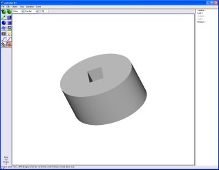
Afterwards, I exported the "design" as an STL file. Here you can see what the shaded solid in AoI looks like as a wire frame representation of its STL file.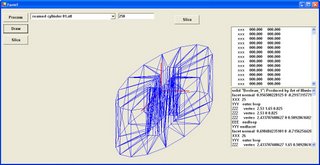
Then you can see what happens when you make multiple passes through the STL representation of the solid form with a cutting plane.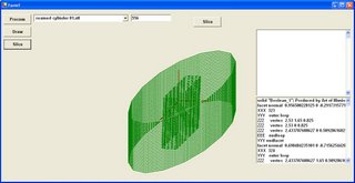
From there we start mapping paths for the Mk II to extrude the solid.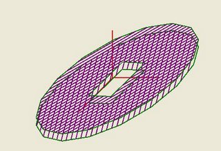
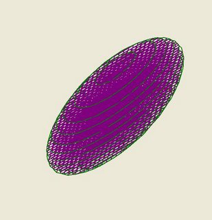 The next step will be to map the boundary paths for the layers.
The code looks fairly robust so far. Mind, I haven't attempt to correct for pixel geometry yet.

Afterwards, I exported the "design" as an STL file. Here you can see what the shaded solid in AoI looks like as a wire frame representation of its STL file.

Then you can see what happens when you make multiple passes through the STL representation of the solid form with a cutting plane.

From there we start mapping paths for the Mk II to extrude the solid.

 The next step will be to map the boundary paths for the layers.
The code looks fairly robust so far. Mind, I haven't attempt to correct for pixel geometry yet.
Sunday, July 30, 2006
Repstraperous
I guess I can no longer call my contraption RepStrap because that word has taken a life of its own. So I'm renaming it after a character in a childrens book I remember reading when I was young, which was "Repstraperous".
I've posted some pics and progress on http://repstrap.blogspot.com/
I'm mentioning it here too, because I know nobody actually looks at that blog :)
Amusingly, it was last July (2005) that I soldered together the first bits of copper pipe. I was somewhat sidetracked by other parts of the project, but I think it's time to get something going for myself too. It's hard to believe a year has already passed. A year is long enough...
But today it finally does something. No Z axis yet, so the next thing to do is build a L298N driver for that.
Comms working again...
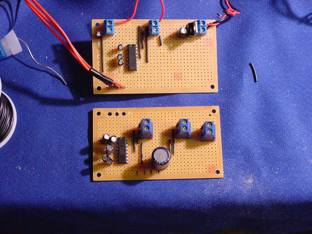
I got my parts consignment at noon today and after discovering that the blown 100 uF capacitor wasn't the only problem that the comms card had I decided to build a new one. The new one is at the top of the pic and the old one is under it. 
As you can see the new card is considerably neater in layout than the old one. Probably the biggest difference was that Randy at Glitchbuster stocks some really short dinky little electrolytic capacitors that take up a lot less room on the board and don't get in the way nearly so much.
I've also stopped trying to use the 5.35v power off of my power supply and have taken to just using regulators to cut 12v down to 5v exactly. I've made that and the serial comms terminals placement on all my boards the same, viz, along the top edge with the 12v supply on the right hand side of the board and the serials comm terminals on the left.
Anyway, I used Simon's diagnostics when I was assembling the board. I then ran a standard serial loop test on it and it fired right up and worked without so much as a hiccough. :-)
I hooked up the Frankenboard and fired up the Frankenmotor with no problems, too. :-D
Saturday, July 29, 2006
Sign For a RepRap
We've had a wee bit of discussion on an idea which we can't really take any further due to lack of all sorts of important stuff like time and resources. But it deserves to be blogged nonetheless. Perhaps someone will even take it to The Reprappers Blogspot, where people who are actually doing some building live :)
The general concept is to use a CNC router to cut sheet acrylic or polyethylene to form the basic essentials of a RepRap prototype for keen hobbyist developers. This is a little controversial, because it isn't a pure-bred RepRap and it isn't a made-from-scratch masterpiece. It sits somewhere in the middle, shuffing its feet uncomfortably. There are two main areas in which this idea has some merit:
1. There is a thriving CNC router community who know a thing or two about desigining axes and stuff. They often have the technology and curiosity necessary to want to play with RepRaps.
2. It turns out these things are readily accessable at reasonable prices to all and sundry, including those to whom CNC is one of the Dark Arts. The local signmakers are a secret clan of machine shops.
Signmakers, you see, take vector drawings and use computerised routers to cut shapes out of sheets of acrylic. These sheets can be up to 10mm (3/8") or so thick, though a reasonable thickness for one-pass cutting is more like 6mm. Holes of 3mm and greater can be cut with the general routing bit. Acrylic and polyethylene are reasonably inexpensive, so materials for the thing could be <$50 for all parts. But...
One of the reasons RepRapping is so appealing is you only pay for what you use. With CNC routing you pay for all the material, and then you pay extra for the "cutting lines" needed to hew your part out. So someone would need to convert the basic "Da Witch" parts, or ther functional equivalents thereof (we've a few sensible changes in mind already), to a 2D vector image (AI, DXF, SVG etc.) using a minimal amount of cutting. Instead of being full of lightening holes to save plastic, for example, the gears would be solid. Other designs are undoubtedly better, but we do know Da Witch actually works.
Given this plan, anyone in a conveniently civilized spot with sufficient cash can then stroll into a signmakers, say "print me one of these on so-many millimetre/inch acrylic, my good fellow, and be snappy about it," and come out with a funny look and snap-off sheet of flat-pack RepRap bits.
It's a thought.
Vik :v)
Wednesday, July 26, 2006
Frankenboard and Frankenmotor with IR Thermometer...
I finally got the camera back after many adventures and post for your delight a pic of the working PWM Frankenboard and Frankenmotor. I haven't installed the shaft encoder and limits detector at this point.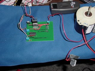
I burned in the board for 20-24 hours before the comms card packed up on Monday night. At the PWM frequency that I'm using the motor will very rarely get out of sync with the pulse train and just stop for no particular reason. That has happened about twice that I've observed. Feedback from the shaft encoder can be used to restart the motor or shut down the PWM signal safely.
That heat sink is really necessary.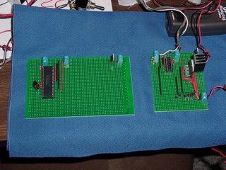
Here's a quick pic of the 16F877A board built out for serial comms.The relative size of the two cpu's is quite astounding. I haven't decided yet whether I want to build this one out as an extruder board or attempt to see if I can drive both the x and z axes (horizontal) with the bigger 16F877A chip.

I burned in the board for 20-24 hours before the comms card packed up on Monday night. At the PWM frequency that I'm using the motor will very rarely get out of sync with the pulse train and just stop for no particular reason. That has happened about twice that I've observed. Feedback from the shaft encoder can be used to restart the motor or shut down the PWM signal safely.
That heat sink is really necessary.

Here's a quick pic of the 16F877A board built out for serial comms.The relative size of the two cpu's is quite astounding. I haven't decided yet whether I want to build this one out as an extruder board or attempt to see if I can drive both the x and z axes (horizontal) with the bigger 16F877A chip.
Tuesday, July 25, 2006
RepRappers of the World Unite!
A number of people who are not members of the core development team have started building their own RepRaps - Welcome to them!
I have set up a blog as part of the RepRap project for any of them who want to record their discoveries, hints, calls for help, pictures of triumphs and so on at http://reprappers.blogspot.com/ .
If you would like to contribute to that blog just e-mail me at A.Bowyer@bath.ac.uk giving a few details of your RepRap project.
Mk2a RepRap Polymer Extruder Head
I've just finished assembling the current generation of polymer extruder heads, which I have taken the extreme liberty of referring to as Mk 2a. I thought a picture might be in order:

Some of the materials are different; the bits attached to the motor are made from SLS nylon, for example. Also I've used Philips head screws instead of cap screws throughout. There are a few other changes from the original design:
o The springs have been replaced with silicone tubing.
o The central channel that guides the filament now has little walls.
o The PTFE rod is now 16mm diameter.
o The nozzle is interchangeable.
o The filament is insulated nichrome, though this isn't working well.
o The coil is insulated and kept stable with fibreglass/plaster.
o The thermistor is on a tag, pierced by the barrel.
Does it work? Dunno yet. I have a Mk2a extruder controller board to build first!
Vik :v)
Monday, July 24, 2006
What we might make with a reprap...
I'm expanding a post that Alex made to my last blog entry because it gives an idea of what one can get up to with a 3D prototyper. The famed Lockheed "Skunk Works" that produced such aircraft as the U2, the SR-71 Blackbird, the F-117 stealth fighter and a variety of other air and spacecraft whose details have never been made public has now created a new UAV called the "Polecat".
According to the New Scientist...
About 90 per cent of Polecat is made of composite materials with much of that material made by rapid prototyping.
Why? It's cheaper than conventional construction methods for very much the same reasons that we've been talking about...
This use of rapid prototyping is certainly a revolutionary approach to making an aircraft," says Bill Sweetman, aerospace and technology editor of Jane's International Defence Review. "The classic way is to set up a production line with very heavy-duty fixed metal tools that hold everything in the right place." That is too expensive an approach for the low production runs that reconnaissance UAVs are likely to need, he says.
The Polecat was recently shown off at the Farnborough Air Show.
I think that we're in very good company here. :-D
Saturday, July 22, 2006
Frankenboard meets the Frankenmotor...
I got the rest of the wiring for the Frankenboard checked out. A loose soldered joint in the H-bridge cost me another PIC, but otherwise there were no problems.
The G4 motor tested out on the parallel wired 4-5 amp board without any problems. Speed, direction and the lot.
I ran it for some time at a PWM setting of 226 (0-255). A few hints for people wanting to use the L298N chip. It's a great chip but you have to treat it with respect
After proving the board on the G4 I shifted it to an unmounted Frankenmotor and then to the mounted Frankenmotor that drives the z-positioning stage (horizontal). I was able to operate the z-stage as is (which means lots of friction) in a translation speed range of 10-30 mm/sec. There didn't seem to be any problems with overheating of either the motor or the H-bridge chip.
The Frankenboard was also tested against the high torque Siemens gearmotor. It is likely that this gearmotor, rather than the Frankenmotor currently installed, will be used to power the y-axis (vertical) on Godzilla. While slow, the Siemens Gearmotor has a very smooth movement and is nearly impossible to stall.
One little added benefit that I discovered is that the magnet that activates the AS5035 shaft encoder chip sticks to the end of the threaded drive rod and centres itself perfectly without glue or any other kind of bother. Every little bit helps. :-)
The G4 motor tested out on the parallel wired 4-5 amp board without any problems. Speed, direction and the lot.
I ran it for some time at a PWM setting of 226 (0
- don't touch the chip while it is running or for some time thereafter, especially if you are testing the board after having built it up and have the possibility of a loose electrical joint in the H-bridge. It gets quite hot, even with a heat sink attached.
- ground the sense pins if you want it to work
- pay especial attention to the orientation of the shottky diodes when you install them. I've got what looks like a fair second degree burn on my index finger for getting that one wrong.
After proving the board on the G4 I shifted it to an unmounted Frankenmotor and then to the mounted Frankenmotor that drives the z-positioning stage (horizontal). I was able to operate the z-stage as is (which means lots of friction) in a translation speed range of 10-30 mm/sec. There didn't seem to be any problems with overheating of either the motor or the H-bridge chip.
The Frankenboard was also tested against the high torque Siemens gearmotor. It is likely that this gearmotor, rather than the Frankenmotor currently installed, will be used to power the y-axis (vertical) on Godzilla. While slow, the Siemens Gearmotor has a very smooth movement and is nearly impossible to stall.
One little added benefit that I discovered is that the magnet that activates the AS5035 shaft encoder chip sticks to the end of the threaded drive rod and centres itself perfectly without glue or any other kind of bother. Every little bit helps. :-)
Thursday, July 20, 2006
The Great Pyramid of Pholymer
I tried doing a true triangular-based pyramid but the software's not quite up to it. Instead, this one has (believe it or not) a slightly flattened tip:

Yeeesss.... It looks like the deposition routine is dumping too much polymer in the tip of the pyramid, causing the whole thing to collapse over sideways in a sort of mini-landslide. It did a very promising start though.
The pimple, slap-bang in the middle of the photographed face (where else on an adolescent?) is caused by the head wandering off to get warm in the middle of depositing the side.
Vik :v)
A new wrinkle on CAPA filament production...
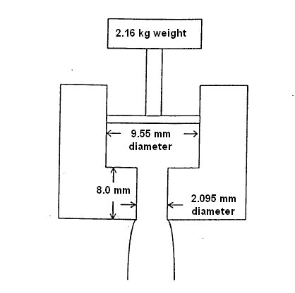
I went back over the filament production issue again and may have just hit upon a new wrinkle. I looked again at the ASTM standard capillary viscometer that is used to measure the melt index of polymers.
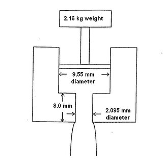
Previously, I had made something like this out of plumbing parts. While my system worked after a fashion there was a problem in fabricating a piston that would force the polymer out of the die. As well, there was a problem in scaling the device up in a way that would let us process a meaningful charge of polymer (~1 kg).
I think that I may have hit on a bit of a breakthrough in that regard by revisiting the diagram of the capillary viscometer and then getting the melt index of CAPA 6800.
http://www.solvaycaprolactones.com/docroot/capro/static_files/attachments/capa_6800.pdf
At 160 degrees Celsius CAPA 6800 caprolactone's melt index is 3 grammes/10 minutes. What that means is that this device, heated to 160 degrees will extrude 18 grammes per hour or 0.4 kg/day of filament which is roughly 2.4-2.5 mm in diameter.
When you think about it that's awfully close to the size filament that we need and the daily production is within shouting distance of what a fully functional Godzilla scale RepRap could use.
Making the die a bit wider so that we could make 3 mm filament would actually make the device work faster, so that's not a problem. As well you could reduce the depth of the die channel which would also speed things up.
So what are the problems?
The big problem is the size of the melt chamber. A chamber diameter of 9.55 mm (3/8ths inch) is too small. The melt chamber is sized to hold no more than 15 cm^3 of polymer. If we keep the diameter as is and increase the height of the melt chamber we can keep the force required the same. With such a small diameter, though, the practical limits of this approach are reached very quickly. If we increase the diameter as we must, however, the force applied to the piston in the melt chamber increases as the square of the diameter. The practical limits of that, for a device that we wouldn't mind having around are also reached very quickly.
Lets take a look at that force for a moment. We are applying 2160 grammes (I know the units are ideosyncratic, but bear with me for a moment) of force to 71.6 mm^2 of piston area. That means that we have about 30 grammes/mm^2. Since 1 atmosphere of pressure is about 10 grammes/mm^2 we are applying about 3 atm of pressure to the top of the melt to get that highly desireable flow rate.
A pressure of 3 atmospheres in US units is about 44 psi. Being an American who has spent much of his life in SI only countries I carry a lot of conversion figures in my head. Last weekend I took Zach down to the Kragen auto parts shop and snooped around while he bought several things that he needed to repair his VW Kombi. I was quite taken with a US$199 generator set rated at 1200 watts continuous. I also looked at a similarly cheap shop compressor and noted that it operated at two pressure ranges, viz, 45 psi and 90 psi, or 3 and 6 atmospheres.
Click!
We're using plumbing parts, right? A pressure of 3-6 atmospheres for plumbing parts should be a walk in the park.
Let's look again at my little filament experiment from a few weeks back.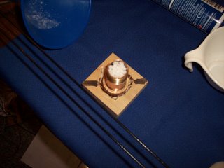
What's to stop us from screwing another brass cap on top of this assembly and tapping a very standard compressor connector to it and then hooking it up to a standard shop compressor to provide the pressure that I was applying manually with great difficulty.
The short answer is... nothing.
Once you fire up the extruder barrel enough to plug the bottom of the barrel you can apply pressure. A 200 mm length of 100 mm pipe would easily hold 1 kg of CAPA 6800 granules.
About the only objection is that a standard shop compressor is massive overkill. We require very little actual air volume, only the pressure.
With that in mind I went shopping and quickly found this...
This is a tiny compressor that you plug into your car's cigarette lighter. It costs US$8.24 and very conveniently runs on 12 volt power.
http://www.nationalonlinesales.com/index.asp?PageAction=VIEWPROD&ProdID=193
It should provide more than enough air volume to do the job.
Heating the barrel is probably more than we can reasonably expect from a 12 v system, though. Happily, our friends at IMS have a solution.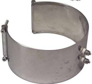
Their mica insulated band barrel heaters are widely used in the plastics extrusion industry. IMS will sell a 100 mm diameter x 100 high unit rated at 750 watts, far more than you need, to you for about US$30.
This should be fun. :-D
Previously, I had made something like this out of plumbing parts. While my system worked after a fashion there was a problem in fabricating a piston that would force the polymer out of the die. As well, there was a problem in scaling the device up in a way that would let us process a meaningful charge of polymer (~1 kg).
I think that I may have hit on a bit of a breakthrough in that regard by revisiting the diagram of the capillary viscometer and then getting the melt index of CAPA 6800.
http://www.solvaycaprolactones.com/docroot/capro/static_files/attachments/capa_6800.pdf
At 160 degrees Celsius CAPA 6800 caprolactone's melt index is 3 grammes/10 minutes. What that means is that this device, heated to 160 degrees will extrude 18 grammes per hour or 0.4 kg/day of filament which is roughly 2.4-2.5 mm in diameter.
When you think about it that's awfully close to the size filament that we need and the daily production is within shouting distance of what a fully functional Godzilla scale RepRap could use.
Making the die a bit wider so that we could make 3 mm filament would actually make the device work faster, so that's not a problem. As well you could reduce the depth of the die channel which would also speed things up.
So what are the problems?
The big problem is the size of the melt chamber. A chamber diameter of 9.55 mm (3/8ths inch) is too small. The melt chamber is sized to hold no more than 15 cm^3 of polymer. If we keep the diameter as is and increase the height of the melt chamber we can keep the force required the same. With such a small diameter, though, the practical limits of this approach are reached very quickly. If we increase the diameter as we must, however, the force applied to the piston in the melt chamber increases as the square of the diameter. The practical limits of that, for a device that we wouldn't mind having around are also reached very quickly.
Lets take a look at that force for a moment. We are applying 2160 grammes (I know the units are ideosyncratic, but bear with me for a moment) of force to 71.6 mm^2 of piston area. That means that we have about 30 grammes/mm^2. Since 1 atmosphere of pressure is about 10 grammes/mm^2 we are applying about 3 atm of pressure to the top of the melt to get that highly desireable flow rate.
A pressure of 3 atmospheres in US units is about 44 psi. Being an American who has spent much of his life in SI only countries I carry a lot of conversion figures in my head. Last weekend I took Zach down to the Kragen auto parts shop and snooped around while he bought several things that he needed to repair his VW Kombi. I was quite taken with a US$199 generator set rated at 1200 watts continuous. I also looked at a similarly cheap shop compressor and noted that it operated at two pressure ranges, viz, 45 psi and 90 psi, or 3 and 6 atmospheres.
Click!
We're using plumbing parts, right? A pressure of 3-6 atmospheres for plumbing parts should be a walk in the park.
Let's look again at my little filament experiment from a few weeks back.

What's to stop us from screwing another brass cap on top of this assembly and tapping a very standard compressor connector to it and then hooking it up to a standard shop compressor to provide the pressure that I was applying manually with great difficulty.
The short answer is... nothing.
Once you fire up the extruder barrel enough to plug the bottom of the barrel you can apply pressure. A 200 mm length of 100 mm pipe would easily hold 1 kg of CAPA 6800 granules.
About the only objection is that a standard shop compressor is massive overkill. We require very little actual air volume, only the pressure.
With that in mind I went shopping and quickly found this...

This is a tiny compressor that you plug into your car's cigarette lighter. It costs US$8.24 and very conveniently runs on 12 volt power.
http://www.nationalonlinesales.com/index.asp?PageAction=VIEWPROD&ProdID=193
It should provide more than enough air volume to do the job.
Heating the barrel is probably more than we can reasonably expect from a 12 v system, though. Happily, our friends at IMS have a solution.
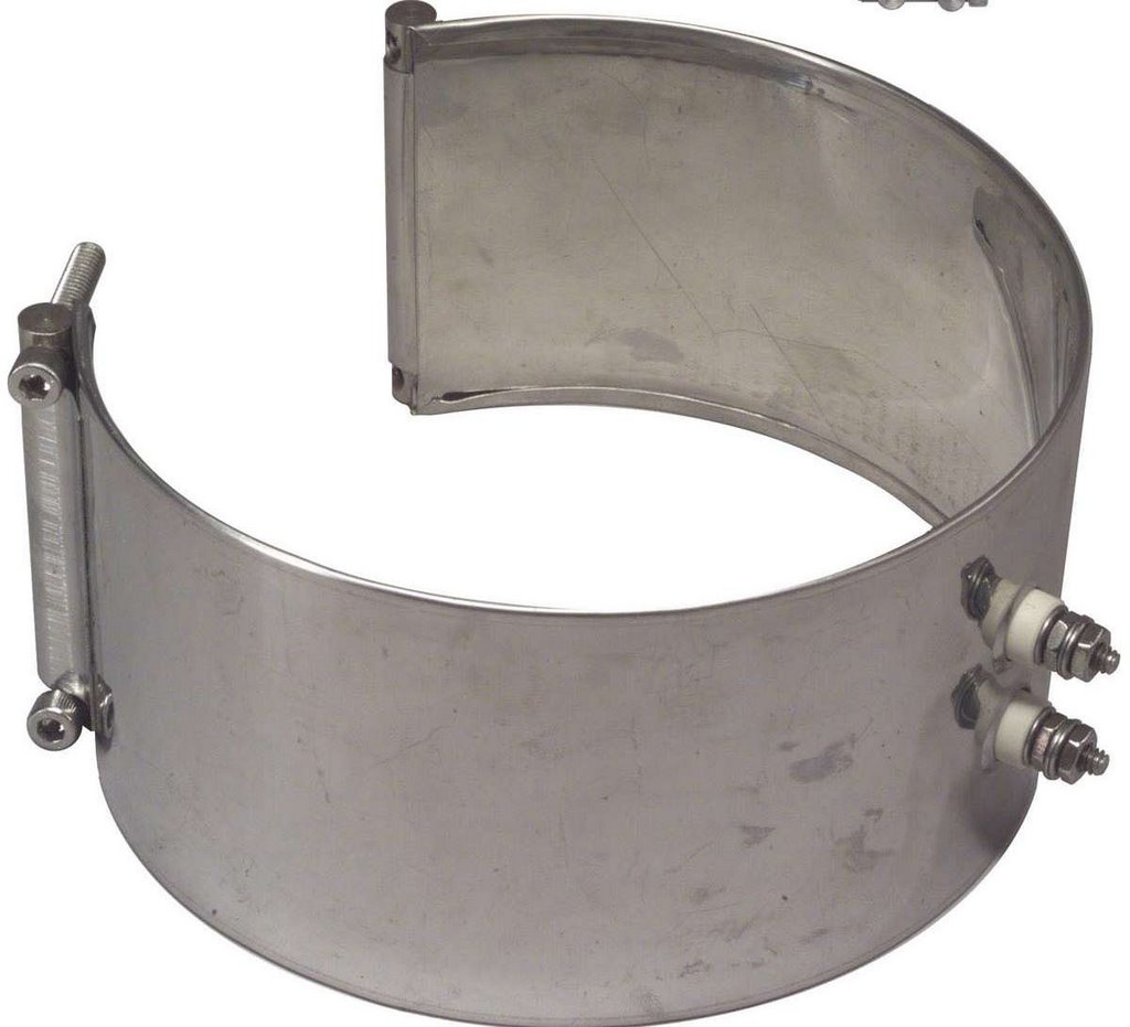
Their mica insulated band barrel heaters are widely used in the plastics extrusion industry. IMS will sell a 100 mm diameter x 100 high unit rated at 750 watts, far more than you need, to you for about US$30.
This should be fun. :-D
Wednesday, July 19, 2006
Feedback control of brushed DC motor speed
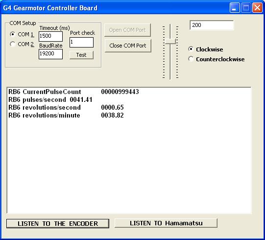
Okay, I've done part of what Adrian wanted. You tell my control board how fast you want the G4 motor to go, the units are encoder pulses per unit of time, and it takes you there and keeps you there. It keeps you within a pulse per unit of time of where you want to be.
There's a tradeoff with the G4, which runs at < 70 rpm. If you keep your unit of time low you get faster motor response, but you also get fewer pulses per unit of time and therefore less control resolution. Make the unit of time too long and you will get whatever drift in motor speed that can happen within that unit of time. You will also be slower to correct when you overshoot.
The magnitude of these problems should be tremendously smaller with the Frankenmotors since they operate at anywhere from 250 -2270 rpm.
One nice feature of the control algorithm is that if you are operating at the low end of the motor's range it will take you down to wherever the lowest speed that the motor will run rather than letting you stall.
Tuesday, July 18, 2006
Controlling speed, direction and position of a brushed DC motor...
I finally cracked using timer 2 on the PIC16F628A chip in interrupt mode. That means that I will be able not only to keep track of where a positioning stage is but also the direction in which it moves and rate at which it moves. 
While I was originally going to calculate the rate via the supervisory comms software in the PC, cracking the problem of using timer 2 in interrupt mode lets me do all that in the PIC chip and also to do it at a much, much finer resolution than would have been possible in the PC.
It's a good thing that the diodes for the Frankenmotors are due in in the morning because with the G4 gearmotor one has to use quite long sampling periods to get a good idea of the rotational rate. I suspect that the AS5040 encoder with 4096 resolution is going to be very handy in that regard with very slow gear motors like the G4.
It is going to be interesting to see if the PIC16F628A has enough memory to allow for sophisticated approaches to DC motor control. I'm not terribly worried about that though because I have the PIC16F877A as a back up with 4 times the memory. :-)
Monday, July 17, 2006
The RepRap mints a polo
Adrian has improved the infill code to the point where it can now fill in the gaps in an annular object - a short, fat tube. The shape is commonly referred to in the UK as being like a Rowntree's Polo Mint ("The Mint With The Hole"), which are now sadly owned by that ethically dubious company, Nestle.
Meanwhile, back off the soap box, I've grabbed a photo of the printed polo with all the little bits of sprue snipped off. Note that about 10 o'clock there is the dreaded dimple caused by the nozzle not having any polymer left in it after it has been moving around. Really must fix that some month soon:

We have even layers, like an onion or possibly parfait. These go round corners and still manage to line up quite nicely if I say so myself. The infill can be tightened up, but I like to see where it's going. The object was cooled for 10s by a fan between layers.
The polo was meant to be 20mm in diameter. 3 random measurements give 19.5, 19.7 and 19.6mm. The centre hole was meant to be 10mm diameter and that gives (avoiding the dimple) 8.3, 9.6 and 9.1 - there's a lot of sprue so it's hard to take accurate measurements inside.
Warning: RepRap'd artificial sweets are a choking hazzard. Keep out of reach of young children and intoxicated students.
Meanwhile, back off the soap box, I've grabbed a photo of the printed polo with all the little bits of sprue snipped off. Note that about 10 o'clock there is the dreaded dimple caused by the nozzle not having any polymer left in it after it has been moving around. Really must fix that some month soon:
We have even layers, like an onion or possibly parfait. These go round corners and still manage to line up quite nicely if I say so myself. The infill can be tightened up, but I like to see where it's going. The object was cooled for 10s by a fan between layers.
The polo was meant to be 20mm in diameter. 3 random measurements give 19.5, 19.7 and 19.6mm. The centre hole was meant to be 10mm diameter and that gives (avoiding the dimple) 8.3, 9.6 and 9.1 - there's a lot of sprue so it's hard to take accurate measurements inside.
Warning: RepRap'd artificial sweets are a choking hazzard. Keep out of reach of young children and intoxicated students.
Sunday, July 16, 2006
Making interchangeable nozzles.
I'm making a variant of the Mk2 extruder nozzle that can be easily swapped out for unclogging, different extrusion diameters and so forth. Details can be found here, and this is a photo of one fitted to a heater barrel:

The heater barrel itself is wrapped in pelican wire - insulated nichrome. I'm using 16mm PTFE rod so I can get higher pressures. The 10mm rod didn't grip the barrel tightly enough when I cranked up the pressure for really small holes, even when I'd put a hose clamp around it.
Vik :v)
The heater barrel itself is wrapped in pelican wire - insulated nichrome. I'm using 16mm PTFE rod so I can get higher pressures. The 10mm rod didn't grip the barrel tightly enough when I cranked up the pressure for really small holes, even when I'd put a hose clamp around it.
Vik :v)
Monday, July 10, 2006
Chips arrive!
The order from Randy with the L298N chips arrived this morning. I wasn't expecting them till Tuesday or Wednesday. Turns out that post from Reno is a lot faster than I expected.
It appears that Randy is going to work out nicely as a supply source. He's effectively reduced the shipping and handling overhead of buying a lot of parts from about 40-60% of the purchase cost to something like 10-15%. His prices are, as well, within a short shout of what I can buy things for from Mouser and Digipen. That lets me buy small lots of parts with a lot better financial efficiency.
I had worried because the pins of the stand-up L298N were offset by 0.05 inch instead of the standard 0.1 inch. The legs are put into two separate rows with alternating pins with one row kneed out away from the chip by maybe half an inch. It's a snap to bias that row just a hair so that they use the same pin hole row on the strip board that the other row does. That's not a wonderful solution but I expect that it will make setting them up on strip board not nearly the chore that I expected that it would be heretofore.
I also got the 40 pin 16F877A chips. They are HUGE! My dinky little stripboards won't accomodate them. Too narrow.
I guess that now I get to see if they work for the Frankenmotors.
Interrupt-driven serial comms no real challenge
When I finally sat down and started writing code it took about five minutes to write a test program for interrupt-driven serial comms for the 16F628A and test it on the simulator. It took another five minutes to program an actual chip, stick it in the test board and make sure that it could do a "hello world" echo. That was a lot faster development cycle than I expected last Friday.
That's the last piece in the puzzle for producing a control board for the Frankenmotors. Further progress now depends on receiving the relevant chips and actually putting one together and testing it. According to Randy that should be tomorrow or Wednesday at the latest.
I think I've now got quite a decent development suite for firmware. I program in BASIC with an integrated development environment and PIC chip simulator from Oshonsoft. Oshonsoft is run by a physics professor who lives in a little village outside of Belgrade. He charges US$67 for an individual license. That's about 25% of the price of most other entry-level commercial, high-level language compilers. It works well.
One bit of supporting evidence that the Oshonsoft BASIC compiler is worthwhile came in at the pic_sim_ide users group at Yahoo a few days ago. Somebody has taken the trouble to write a crack that gets software pirates past its license requirement. From my experience having a crack for your app appear in the peer-to-peer filesharing world is as good as a certificate of merit. :-)
After a lot of stress and strain with my home-built JDM programmer, which I estimate cost me about US$20 in parts and maybe US$5,000 in distress at the end, I finally settled on a MELabs USB programmer. Their USB programmer bundled with a 40 pin ZIF socket and software cost about US$115. It's a very "smart" PIC programmer built around a PIC18F chip. Smart is what I need. It very forgiving of my clumsiness and foibles. For example, I get a nice error message if I get the PIC chip in backwards. I once also accidently put a SN754410 chip in the thing and it politely told me that it definitely wasn't a PIC chip. I need that sort of backup.
While I understand completely the desire and need for using open source software and technology for RepRap in the longer run, I think that if you want to get a lot of eyes and hands on firmware development this is a fairly decent route to take.
As I said some time ago I expect that for every potential developer out there who is useful in the C language there are probably several hundred who can tinker in BASIC who might find firmware development for as focussed a piece of technology as RepRap a lot of fun. :-)
Sunday, July 09, 2006
Printing a real part
So I had to cap Ed's Z-axis, Adrian's peristaltic prototyped polyfilla pumper, and Forrest's working opto interrupt. It was tough. May I present my first attempt at printing a bona fide RepRap component, the 6mm stage linkage (known as a "gripley" locally, in honour of Terry Pratchett):

For those who suffer more delusions of grandeur than I, the top one was made by a Stratasys from ABS and I did the skeletal one from Polymorph (must've rolled a metre of it so far today). The bottom part was extruded using the Da Witch prototype. The extrusion was made using a 0.8mm nozzle at 80C, fan-cooled by manual intermittent fan operation. The deposition was halted at 3mm, and the wall thickness is a very constant 1.0mm - at long bleedin' last!
The deposition surface was a cheap Vietnamese wooden chopping board (NZ$3, The Warehouse), from which I had sanded off the varnish. I knew all that sandpaper would come in handy :) The old varnish, whatever it was, stuck to the polymer like glue. This might be useful, and I might get some cheap spray-on varnishes to experiment with as a light spraying on glass may provide enough adhesion. The adhesion to the base wasn't what I'd call excellent, but it was a freshly-sanded surface and some dust may have been present. We'll see how it goes; it'd rather steer clear of wood due to its tendency to warp.
Please excuse the tatty and somewhat sparse infill, but this is only the second complex object ever to have been printed and the filling algorithm needs a bit of tweaking. Nevertheless, I'm really happy with this lot. It shows we're definitely on the right track.
I suspect we may be able to make depositions like these using a ducted fan for continuous cooling. There is still lots of experimenting ahead. But time to sit back with a Cointreau & vodka, and relax for the evening I think.
Vik :v)
Well THAT was easy!
No problem with the Hamamatsu photoreflector chip. Put it on interrupt on RB6 and it ran on the third time I tried it. 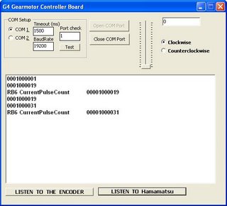
It appears that you have to be a little way away from the chip before it sees its reflected light signal. Once I understood that it was no problem getting it to pulse.
Hmmm, I'd planned on that taking longer than it did. I guess I'd better get on with trying to do interrupt-driven serial coms now.

It appears that you have to be a little way away from the chip before it sees its reflected light signal. Once I understood that it was no problem getting it to pulse.
Hmmm, I'd planned on that taking longer than it did. I guess I'd better get on with trying to do interrupt-driven serial coms now.
Saturday, July 08, 2006
Peristaltic pump go after all!

Gave up too soon (see blog right below)...
Jonored's neat idea (see the comments on that blog entry) prompted another experiment. Instead of having the extruder nozzle right after the pump, I put a length of the flexible tubing after it. That acts as a pressure reservoir, and evens out the flow beautifully. (The beaker of water is just so I can park the nozzle in it, turn everything off, and go for coffee without it clogging; on a RepRap machine it would probably be a piece of damp felt in the write head's parking place.)
Now, of course, turning the pump on and off doesn't turn the flow on and off - there is a huge time delay that would be impossible to allow for in software. But I already have a really simple solenoid valve design that works by pinching a soft tube like the one in the peristaltic pump. All I need to do is to install that just before the nozzle and use that to control the flow.
The soft tube swells perceptibly under the pressure. This, of course, gives a really simple way to switch the peristaltic pump on and off - just use the swelling to trip a microswitch. No computer needed...
I'm extruding "Fine Surface Polycell Polyfilla" which seems to have near-perfect characteristics for this (including being really cheap and being available at every DIY shop). Many thanks to my Final Year student James Low for all his work on that, which is really paying dividends. The syringe at the top of the picture is the reservoir of Polyfilla. An obvious design change is to junk this and just to run the peristaltic tube to the screw-on cap of the Polyfilla tube (which is like a giant tootpase tube).
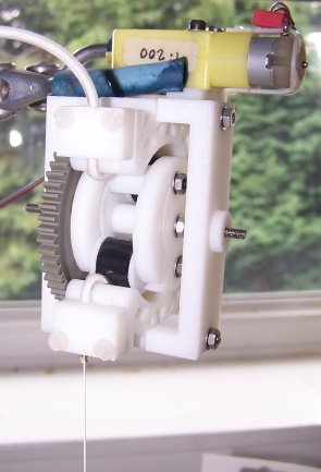
Here is a shot of the bits of the pump.
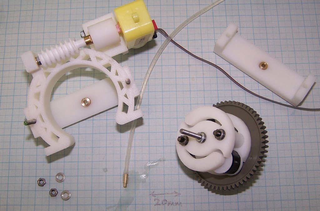
The gears are two that I happened to have lying around. But now that Vik and Forrest have sorted out how to RP gears (see here) they should be easy to replace. The nozzle is made from brass in just the same way as the bigger one on the Polymorph Extruder. Apart from those the only non-RP parts are the motor, a couple of brass bushes, and some lengths of threaded M3 bar.
It has the ability to take one or two tubes. Two tubes could be used, for example, to carry an epoxy and its catalyst. They would be mixed in the nozzle. If two different diameters of tube are used it's easy to change the volume ratio of the mix.
The nozzle could be disposable - the first thing the RepRap machine would do at the start of a build would be to make one or two new nozzles for next time...
Peristaltic pump no go
The peristaltic feeder pump for cold pastes (like Polyfilla) has a fundamental problem. Here it is working, and you can see that it produces a clean stream of paste (about 0.5 mm in diameter) at the bottom of the picture.
But the tube that forms the pump has to be flexible. This means that, when a pinch wheel goes out of contact with it, pressure is released and the back pressure from the nozzle causes the paste to rush back up the tube (which expands a little to accomodate it). So the device produces an intermittent stream - it's off half the time, and on half the time. The problem could be reduced by having more pinch wheels (my design uses two), but can never be eliminated as far as I can see. A bit of a pity, because the pump is compact and easy to make.
Back to James's driven syringe (which works...).
Wednesday, July 05, 2006
Done with shaft encoding...
I got the firmware for the little yellow G4 and the AS5035 shaft encoder doing what I wanted last night. We've got direction and speed control via PWM and feedback on both via the AS5035 chip. The shaft encoder chip is everything that Vik and Adrian said it was.
I have some L298N H-bridge chips on order, but my supplier seems to have gone on Summer holiday, so I'm stuck there unless I want to reorder from Mouser or Digipen. Using what I know to run the Frankenmotor seems to be the next logical step, except that the L298N's that I need for that are not in hand yet.
If Randy stays gone for a few more days I'll see if I can get interrupt-driven serial comms going and maybe try out those Hamamatsu chips for limits detection.
One thing that's become rather obvious is that I want to do more firmware programming than there is memory in the 16F628A. I'm currently up to 1.4K out of 2K available. I've ordered some 16F877A's which have 8K and cost roughly twice what the 16F628A does. The only drawback to those is that you absolutely have to use an external clock chip with the 877A and those run cost as much as a 16F628A. Anyhow, that lets me to use 20 MHz which gives me 5 times the processing power.
I'll be swapping over to the 18F chip family pretty quickly, though. Those come with up to 64K memory and on-board 8 MHz crystals at about US$4-5/unit. They also have lots of port pins and A/D channels to boot. They also give me USB capability.
True Grit
Encouraged by the great performance of Ed's Z axis, I've fired up an experiment he's been asking for. I've done an extrusion on 240 grit sandpaper (some ask about the scale; the hexagon is 16mm (0.63") in diameter):

Note the relatively well-formed sides, extruded as 0.5mm thick layers. Between each layer, the fan was manually run while the outline was being printed. This seemed to cool things off enough, though there's no ducting to protect the heater yet. As expected, the polymer stuck to the sandpaper like, well, glue sticking to sandpaper really. Of course, the sandpaper is stuck to the glass sheet with glue to keep it flat. The Tower Of Ooze (right) came off OK, but the hexagon was stuck solid. So I end up trying to pull things off a sheet of thin, cheap glass and you know what'll happen if I persist in doing that... Fortunately the paper tore before the glass broke.
I'll do one or two more experiments with the sandpaper - might as well use it while it's stuck there - before washing the glue/sandpaper off and trying a different size grit.
Vik :v)
Tuesday, July 04, 2006
ARNIE z-run performance
ARNIE's studding tranmission upgrade was tested on Friday. The stepper motor was directed to rotate 1000 steps and back again 10 times with a delay of 100 cycles per step. A calliper was used to measure the position of the z-bed at the start and end of each run. The figure below shows the results for this test.
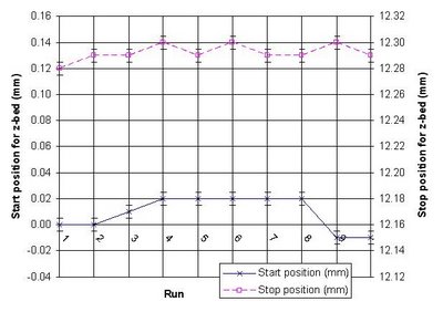
It shows a variation of ± 0.04 mm and ± 0.03 mm variation for both start and end positions respectively using the studding transmission for the z-bed. Not bad, 'specially since we're aiming for an initial accuracy of 0.1 mm. Happy days.

It shows a variation of ± 0.04 mm and ± 0.03 mm variation for both start and end positions respectively using the studding transmission for the z-bed. Not bad, 'specially since we're aiming for an initial accuracy of 0.1 mm. Happy days.
Monday, July 03, 2006
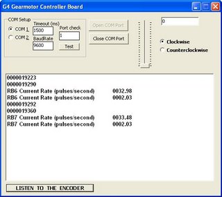
We got shaft encoder pulses on the PIC!
It tooked a fried PIC and a bunch of soldering, but I am reading encoder pulses off of the Austria Microsystems AS5035 chip that is tracking the rotation of the little yellow G4 gearmotor via a magnet glued to the end of the drive shaft.
I got interrupt-driven sampling of the output off of the encoder chip going after a session with a much simpler test board revealed that what I was doing wrong with making interrupts work had nothing to do with my PIC programming but rather my soldering.
That last problem that cost me so much time was not remembering that I leave "unused" pins on the PIC socket dry on the stripboard. I'd built the board when I was trying to use PWM to control the rotational speed of the G4. When I soldered the dry joints on the new connections from the encoder chip things started working fine.
Once I did that the PIC simulator's results began to look like what the control board was giving me.
I've got both pin RB6 and pin RB7 passing pulse counts to my PC. Next is to get the direction and after that to go after Adrian's idea of feeding a speed and destination to to board and having the board do it. :-)
Sunday, July 02, 2006
Fan-boys and hairspray
I've hooked up a 6 inch 12V cooling fan over the workpiece, manually operated for the moment. Cools everything down in about 15 seconds - including the extruder, causing many reheat pauses and making deposition proceed at a glacial rate. I tried giving it 8 seconds of cooling, but that's not good enough. The objects come out all distorted still. It has to be cooled solid. Looks like some ducting is needed to avoid cooling the extruder too much, and maybe a smaller fan would be better.
In an attempt to make things stick to the glass substrate, I sprayed the glass with a thin layer of "extra firm" hairspray purchased specially for the occasion. To the touch, it feels much less slippery. In operation, the plastic deposits fine onto it.
The problem comes with the new cooling. This causes the plastic to shrink slightly, and I suspect that this is causing the break in adhesion on any relatively rigid surface be it glass or hairspray lacquer.
Too little adhesion, and things curl up. Too much adhesion and you'll never get the blooming thing of. So, I have obtained a range of different sandpapers, and over the coming week (once I've fiddled with the fan and ducting a bit) will attempt a series of cooled depositions on the various grits.
Vik :v)
![]()