Monday, July 03, 2006
We got shaft encoder pulses on the PIC!
It tooked a fried PIC and a bunch of soldering, but I am reading encoder pulses off of the Austria Microsystems AS5035 chip that is tracking the rotation of the little yellow G4 gearmotor via a magnet glued to the end of the drive shaft.
I got interrupt-driven sampling of the output off of the encoder chip going after a session with a much simpler test board revealed that what I was doing wrong with making interrupts work had nothing to do with my PIC programming but rather my soldering.
That last problem that cost me so much time was not remembering that I leave "unused" pins on the PIC socket dry on the stripboard. I'd built the board when I was trying to use PWM to control the rotational speed of the G4. When I soldered the dry joints on the new connections from the encoder chip things started working fine.
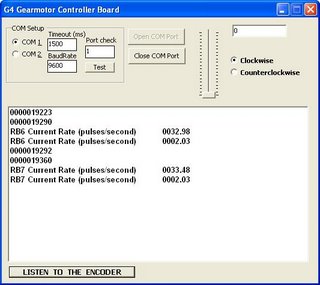
Once I did that the PIC simulator's results began to look like what the control board was giving me.
I've got both pin RB6 and pin RB7 passing pulse counts to my PC. Next is to get the direction and after that to go after Adrian's idea of feeding a speed and destination to to board and having the board do it. :-)

I got interrupt-driven sampling of the output off of the encoder chip going after a session with a much simpler test board revealed that what I was doing wrong with making interrupts work had nothing to do with my PIC programming but rather my soldering.
That last problem that cost me so much time was not remembering that I leave "unused" pins on the PIC socket dry on the stripboard. I'd built the board when I was trying to use PWM to control the rotational speed of the G4. When I soldered the dry joints on the new connections from the encoder chip things started working fine.
Once I did that the PIC simulator's results began to look like what the control board was giving me.
I've got both pin RB6 and pin RB7 passing pulse counts to my PC. Next is to get the direction and after that to go after Adrian's idea of feeding a speed and destination to to board and having the board do it. :-)
![]()