Monday, January 30, 2006
Torque Calculations for Vertical Power Screws
The vertical axis is another matter, however. In my own design the vertical axis steppers must lift not only the extruder but also the positioning systems, structural parts and guide rods for the horizontal axes. In other designs being developed the whole working surface plus whatever it is that is being fabricated wants lifting.
After I acquired the high torque NEMA 17 steppers I noticed that the 24 volt power supplies that they needed for achieving their peak torque performance were considerably more expensive than the much more ubiquitous 12 bolt supplies for a given watt rating. Checking with the manufacturer I learned that while there was no real problem with using 12 volt supplies with them I could expect their torque performance to drop off by roughly half with the halving of the voltage supply. I then began to wonder whether the four NEMA 17's operated with 12 volt power were up to the job of moving the vertical axis loads on my very large, heavy RepRap design.
I was able to quickly establish from load tables on screw jacks that they ought to do the job. Shortly afterwards I found a little paper giving a methodology for calculating such torque requirements. I've reworked the methodology therein into the attached paper which you might want to use if you have similar worries about stepper loading.
http://reprapdoc.voodoo.co.nz/pub/Main/FAQ/TorqueCalculations.pdf
I ran several examples and the results agree fairly well with the screw jack tables on the web. There is a worked example at the end of the paper for a 3/8-24 threaded rod. That is a shade bigger than the 8 mm threaded rods that several of you are using but still very similar.
In using this methodology please keep in mind that I make no claims for it's robustness. It has been nearly 40 years since I took dynamics in engineering school and there were several problems in derivations in the source paper that I was able to see that I tried to work around. It might give you an idea whether a stepper's lifting capacity is up to scratch in extreme cases like mine though. I always try to use a 100-250% safety factor when I design things.
If our blogs have any dynamics boffin readers I would appreciate any suggestions or criticisms of what I have cobbled together here.
One last thing, the header rather cheekily refers to the paper as "A Scientific Report". I make no such claims. That is an artifact of the Scientific Notebook template that I used when I put the paper together. I've not yet got sophisticated enough in using the text editing aspect of Scientific Notebook to figure out how to turn that header into something more appropriate.
RepRap at LCA2006
Everything worked very well indeed after a bit of run-around trying to
sort out clamp stands, hotplates, close-up cameras and so forth.
I have assembled the linear stage, and with the exception of the linkage
(redesign in progress) it works well. I have reduced the component count
to 42 components (every nut, bolt and washer) of which 5 are FDM'd and
no component modification is required other than cutting to length. I
need to taper a recess, add limit switch mountings, reduce the volume of
plastic needed and then I'll try a Mk 2. The axes will stack to
make an X-Y table. If Simon can get code to drive 2 steppers off one
PIC, it'll make for a very tight little unit.
Fortunately Suz came to the conference shortly after me, armed with a box of goodies from the Stratasys. I Assembled the Mk 1 stage from the parts that night, with no modification needed that one couldn't do without a penknife. Here is the beast:

The star-shaped holes allow standard bolts to be used as accurate
self-tappers (saving on nuts), and grip smooth shafts well. They should
allow us to eliminate some of the clamps and their attendant nuts &
bolts - also some of the more ungainly support material.
The presentation itself went flawlessly, with the TIP-based extruder
extruding nicely in front of the close-up camera. For a Polymorph demo,
I turned a hard Polymorph pancake into an amorphous mass, then into an
apple-piercing dagger. Wood's metal was demonstrated by casting shapes
in nothing stronger than filter paper.
After the presentation I was swamped by a rush of geeks, wielding
cameras and wanting to know if it was OK to photograph the mechanism :)
I actually ended up on national TV, but sadly the RepRap was not
mentioned. Linux was a hard enough concept for the news team to get
their heads around.
I spoke to MIT's Jim Gettys of the One Laptop Per Child project, who is
sympathetic to our cause but has other problems to deal with right now.
The good news for us is that he plans to release a "Hacker" version of
the OLPC which comes without case and with access to built-in ports that
the OLPC is not otherwise interested in.
I also spoke to Dr Wayne Piekarski from the the University of South
Australia who is well-known for his work on virtual and augmented
reality systems. Some of his students are developing a CAD/CAM system
and would like to get hold of one of our extrusion heads for it. Wayne
got a "Best Of" slot last year.
In all an extremely satisfying and totally knackering week.
Vik :v)
Friday, January 27, 2006
Steppers vs. Servos

At the RepRap project we have a never-ending discussion about the relative merits of stepper motors (simple, implicitly digital, but low torque and expensive) and DC motors (more complicated to control, but high-torque and cheap). This small discussion mirrors a much larger one that has been going on for years in the machine tool and robotics industries. It hasn't been resolved there, so we probably won't arrive at a definitive answer either.
To start with, RepRap will most likely use steppers, as we don't need a lot of torque (additive manufacturing is inherently very low force) and their simplicity of control cuts down on electronics - a big bonus.However, I though I'd see if I could make a very cheap and simple DC digital servomotor using rapid prototyping. It's depicted above. I've put preliminary details on the RepRap Wiki.
Wednesday, January 25, 2006
Capturing OpenGL data for prototyping
Recently, we had a blog about an open source 3D scanner. Here is another opportunity in that area. A lot of 3D information banging around the internet is in OpenGL format. Now you can grab 3D descriptions out of those visualisations for prototyping and other uses.
OGLE (i.e. OpenGLExtractor) is a software package by Eyebeam R&D that allows for the capture and re-use of 3D geometry data from 3D graphics applications running on Microsoft Windows. It works by observing the data flowing between 3D applications and the system's OpenGL library, and recording that data in a standard 3D file format. In other words, a 'screen grab' or 'view source' operation for 3D data.
The primary motivation for developing OGLE is to make available for re-use the 3D forms we see and interact with in our favorite 3D applications. Video gamers have a certain love affair with characters from their favorite games; animators may wish to reuse environments or objects from other applications or animations which don't provide data-level access; architects could use this to bring 3D forms into their proposals and renderings; and digital fabrication technologies make it possible to automatically instantiate 3D objects in the real world.
http://ogle.eyebeamresearch.org/
Tuesday, January 24, 2006
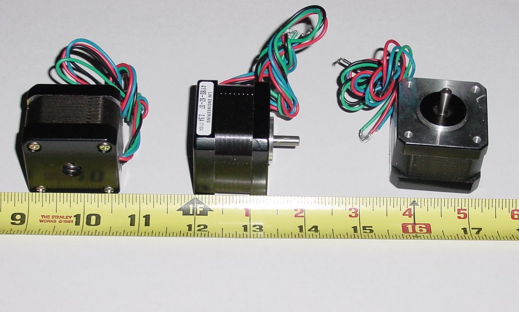
Steppers for Africa!

I'll be transhipping part of the order to Vik and Simon as soon as I get the address for Vik's US maildrop.
Here is a closeup with a rule so that you can get the scale of them. They're NEMA 17's and can be found on Lin Engineering's web catalog at...
http://www.linengineering.com//site/products/4118.html
They're 4118S's and weigh in at 0.4 lbs (182 g) each. They draw 2.5 amps at 24 volts and put out 45 oz-in's (3240 g-cm). For Simon, they've got four leads. I hope they do the job.
Monday, January 23, 2006
Concrete ideas
The part would need to have built-in keys to ensure the filler remained in place, and cross-bracing to ensure it did not bulge when filled.
Vik :v)
High Temperature Materials
http://www.azom.com/details.asp?ArticleID=1458
http://www.mkt-intl.com/ceramics/machinable.html
and
http://www.cotronics.com/vo/cotr/pdf/onepg700.pdf
The last is about castable materials, and of course RepRap should be able to make moulds with no problem at all.
Update on the Gingery filament extruder...
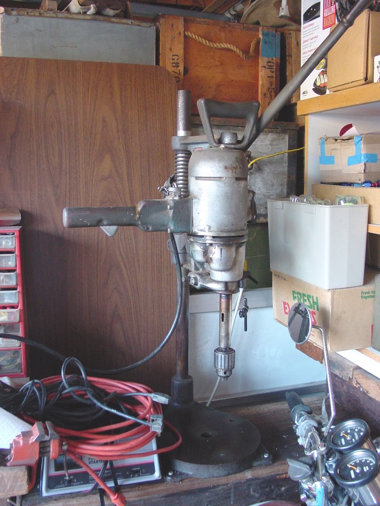
 I finally learned what to call the little positioning table (a cross-slide vise) on a drill press, something my WWII era Black and Decker navy drill press doesn't have. Once I had the name I was able to find a deal on a good machinist's cross-slide vise for US$25.99 on the web. With that installed I will be able to operate the drill press by myself and take on tasks like converting brass bolts to extruder barrels without the fear and loathing that such tasks had previously for me.
It finally stopped raining and dried out this weekend so I packed up the Gingery extruder and drove out to my sister and brother-in-law's place to learn how to weld. I spent a very frustrating hour learning how to strike an arc. After that things moved along and I got the welding on the extruder frame done. I think that I must qualify for some prize for ugly welds, but they are strong and a grinder forgives many sins. My US$65 Chinese welding machine seems to do the job quite nicely. :-)
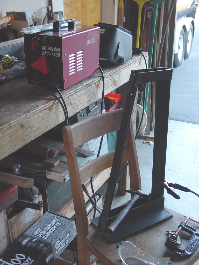
I took some pictures of the welded frame so that I could share the shame of my ugly welds with the team.
Friday, January 20, 2006
Axis controller & extruder prototype boards

There are no comms on it yet, but it has manual controls for stepping backwards/forwards. The red dot on the PIC indicates that I've blown up the serial interface on this chip. The whole thing cost about NZ$20 to build using stock parts from Dick Smith Electronics - our local hobbyist electronics store.
The extruder controller below was also assembled from DSE parts at a similar cost. It differs from Adrian's design in that it used TIP31 transistors to control the motor and heating element. The one strapped to the sheet of aluminium controls the heater.

I've put the MAX233 RS232 converter on this board too, but it can be hacked off once development is complete. As you can see, both boards are relatively simple. What you can't see is that no tracks need to be cut for construction.
Vik :v)
Wednesday, January 18, 2006
Make your own plastic for RepRap
http://www.chemsoc.org/networks/learnnet/green/docs/plastics.pdf
The one we're considering is polymerising lactic acid, as that can be made by fermenting starch from biomass (which is self-replicating, like RepRap...).
Closing in on Godzilla...
 It's big... it's ugly... it uses seven steppers... but I think it will work. Work space is about 750x750x300 mm. It can fabricate something with a 1000 mm maximum dimension. It has a theoretical resolution of .01 mm.
The design has several advantages. It's scalable and the steppers don't have to be very big. I swapped around the axes so that the z axis, which has four steppers, also requires the most torque. The vast majority of the stepper usage will be limited to three steppers rather than five, as it was in the first design iteration.
I've specified NEMA 17's, which are probably overkill. I can get them for US$9.95/unit, though. If Simon's experiment is successful I'll be able to run this with a 120-150 watt power supply and three controllers.
There is also no reason whatsoever why we can't use it to fabricate a stepper-powered lazy suzan that we can centre in the work space and use the reprap along one centred axis to make radial objects like gears and such not till the sun goes cold.
I haven't shown cross-bracing.
Monday, January 16, 2006
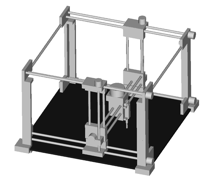
Fourth Round Dieting...
I shifted the design over to DC encoded motors from steppers from standard steppers. I also fixed the threaded rods and made them do double duty as structural members. This entailed moving the motors out onto the moving platforms, a move that will require some bit of coiled power cord which wasn't required before.
Please note that cross-bracing isn't shown.
The net result was that the design shed nearly 22 kg of expensive steel rods and several kilograms of polymer.
The quantity survey takeoff on the design is now...
Polymer - 9.5 kg
Steel - 10.3 kg
Glass - 21 kg
The design specifies 16 mm threaded steel rods. It is possible that smaller diameter rods may work or that we can thread tubing. Losing half of the rods mass out of the middle of the cross section would lower the rod's strength only about 10% if memory serves.
Friday, January 13, 2006
Third Round
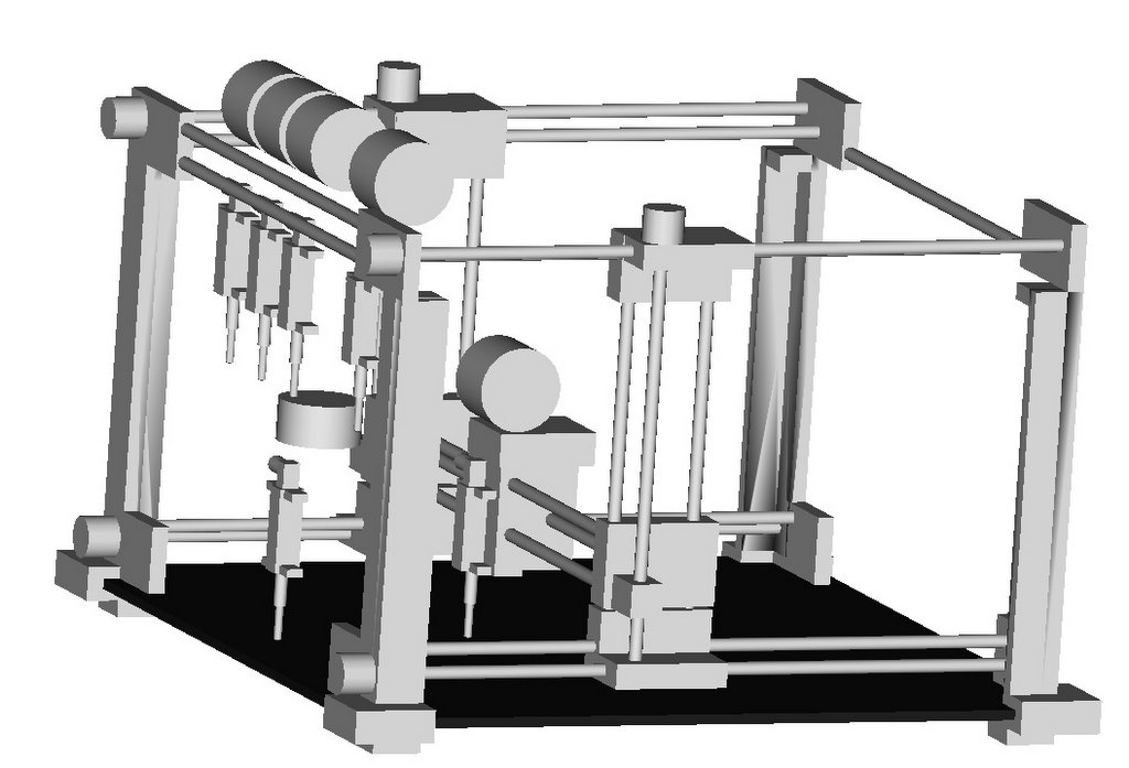 I did a quick volumetric study last night and this morning to explore the issues implicit in docking MK2 extruders in my godzilla reprap design. Not to many problems popped up.
The design accomodated 5 MK2's in a row or 10 in two rows if you sized the filament can down slightly and turned it on its side. One of the big cans will give us 50-60 hours of continuous operation. If you had two extruders of the same specification you could insure pretty much uninterrupted operation.
It seems most reasonable to have the dock use spring steel clips and put a servo driven coupling device in the 3D positioning head.
Thursday, January 12, 2006
PCB production
Instead use electrochemical machining. I put a blank PCB in a bath of concentrated salt (NaCl) solution and connected it as an anode to a 12v supply. I used a soft-iron lead from a resistor as the cathode and held it a very short (0.5mm? I didn't measure it) distance from the copper of the PCB. The cathode had plastic sleeving round it in an attempt to cut out extraneous "sideways" currents. I set up a little fish-tank pump to circulate the solution and squirt it directly at the cathode to stop local build-up in solution of reaction products.
When I turned on the current (about 200 mA according to the meter) it punched a hole through the copper pretty quickly (about a minute). But the hole was about 2mm in diameter, which was a bit big.
I'll do some more experiments and blog some pictures soon.
If it can be made to work you could have an array of cathodes, each switched on and off as the array is scanned over the copper surface in X and Y to remove the copper in the pixel pattern of the PCB you want. If the scan happens from one edge of the board to the other, there is always going to be continuous copper on the unscanned side to ensure that islands (that cannot be removed as no current gets to them) don't occur.
Wednesday, January 11, 2006
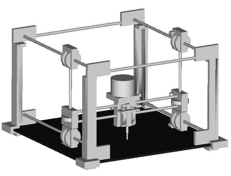
Second Round
 The more I looked at this weekend's design the less I liked it. It just lacks elegance. I hate designs that degenerate into more patches than design.
Last night I had a small epiphany and threw out the geared vertical axis drive and decided to do the whole thing with threaded rod drives. This design emerged from that restriction.
I think that this one is stable enough to use for an anvil. It looks to me to be an intrinsically stable design, which my last effort was not.
It has seven steppers. I am pretty sure that I could reduce that to four, though that would mean adding some material to the design, something I hesitate to do. I would rather use a lot of small steppers working in tandem than fewer, larger ones.
I will probably hate this one tomorrow, too... ...but that is what doing design charrettes is all about, hey? :-)
Tuesday, January 10, 2006
Weekend Design Charrette

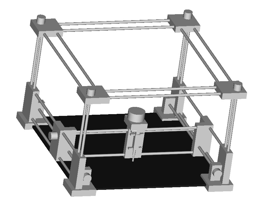
I spent the weekend using AoI to explore the volumetric aspects of using existing design approaches to create a Cartesian reprap machine. The chief difference between the machine designed and existing efforts is that the extruder rather than the working surface is moved along the vertical axis.
A 12 mm plate of tempered float glass is used for the working surface. The machine's footprint is roughly 90x90x60 cm. The working volume for the design is about 70x70x36 cm.
Saturday, January 07, 2006
Duplicate Extruder Mechanism Mk2 Operational
The nozzle exit hole was 0.5mm diameter and the outflowing Polymorph between 1.5 and 1.4mm in diameter - somewhat more than expected. Our average nozzle temperature was 105C.
I've put a page up in the Wiki on this one because it uses halved washers and Polymorph to make the half-round bearings called for in the design.
Vik :v)
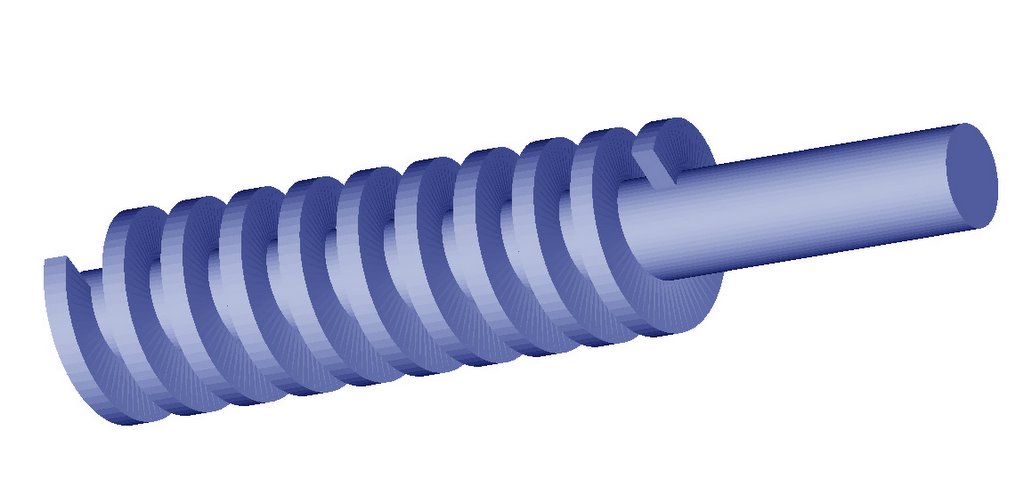
And finally the auger...
Which lets me get on with modeling the version 2 filament extruder.
Friday, January 06, 2006
Pulley accuracy test rig
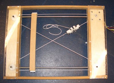
Results on the nylon cord will follow next week.
eD
Thursday, January 05, 2006
Threaded Rod Object done...
 Okay, the routine that creates threaded rods in Wavefront Object format for AoI is pretty much done. I've got it creating a bound solid that works with AoI's boolean feature, though what comes out of the boolean operations can be a bit wierd at times. I'm not sure whether this sort of object is simply too complex for AoI's boolean operator routine or if the routine requires something like a right hand rule for outward facing polygons. I may have some problems with the polygon loop descriptions and got a few of them backwards.
Now I've got to throw in some parameters to dictate the pitch and depth of the threads. You can already control the number of turns of the thread and the resolution of the object.
Anybody who needs one or more of these Wavefront Objects for presentation work in AoI let me know your requirements and I will try to grind them out for you. After I get those extra parameters put in I will be going on to create an auger object for my version 2.0 filament extruder design project.
Wednesday, January 04, 2006
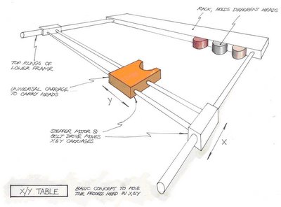
What eD's doing
I'm devloping a mechanical 3D rig, simlar to Vik's. The top tray will be a bog standard carriage assembly:
 The trick to these things seems to be in the z-axis. Whereas Vik is using studding and a spider to move the z-axis, I'm exploring the possibility of using string. Here's the general concept:
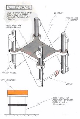
I'm currently working on how feasible the idea by building an accuracy test rig. Will keep you posted...
eD
Monday, January 02, 2006
Additional primitives for AoI?

Our rainy season has arrived with the consequent floods, landslides, cold and humidity making staying in the workshop a very unpleasant experience. Rather than waste the time I've started getting acquainted with AoI indoors in the warm.
While I am awestruck with the capabilities of AoI, the paucity of primitives has made many modeling tasks tedious and others downright impossible. It seemed that AoI would be a lot more useful if a few extra primitives like cones, hexagonal prisms and helixes were added. In that AoI allows for the importing and exporting of Wavefront object files I have begun writing a few simple programmes to generate some of the forms I need directly instead of building them up within AoI using boolean operators and curves. My projects right now are to describe an auger and a threaded rod.
As you see, so far I've generated the helix necessary to building both of those two forms and I've got a start on the threaded rod.

If anybody has any pet peeves with AoI that would be ameliorated with an imported object file not easily buildable with the existing primitives or two let me know and I will see what I can do. I am thinking that it might be nice if I made the specification and building of such objects accessable over the web and intend to do that for a few shapes as soon as my son gets the ASP specification working on Apache in our server.
Simple 3D Scanner
![]()