Saturday, May 14, 2005
The Icing on the Cake
- You can work at room temperature,
- You can get any viscosity you like by changing the sugar/water ratio (mix in a little glycerin too),
- It is completely benign,
- It holds its shape perfectly when you lay it down,
- Fine strands set very quickly because they have a high area:volume ratio for water evaporation (especially if you hit them with a few seconds from a hair dryer...), and
- It sets like a rock.
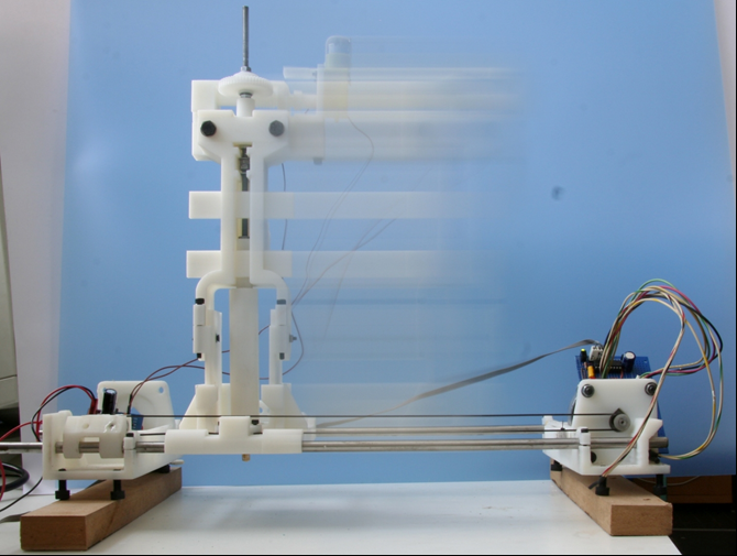
So I dug an old Cartesian robot out of a cupboard at the University (it was made in the 1980s...), upgraded its electronics so they were the size of a dictionary, not a suitcase, and put one of our syringe pump heads on it (the pump contains the first part out of AoI Vik mentions below). The pump has one of our heating jackets round it, but I didn't use that for these experiments - hence the unconnected angled hole at its front. Here it is (with the head enlarged top right):

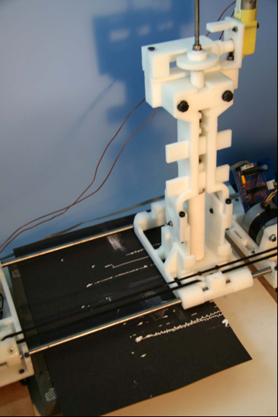
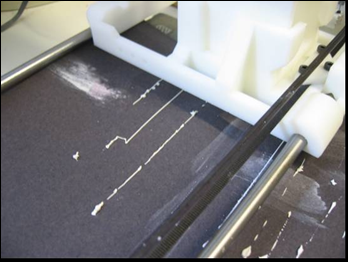
I filled the pump with icing sugar and set it scribbling. It quickly became obvious that the secret is flow control (note panic button added as an afterthought to the syringe pump...). By adjusting the pump voltage, however, it was quite easy to get a good consistent track:

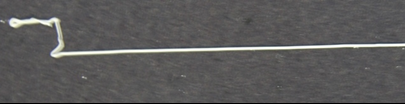
The good track is actually two, one laid on top of the other after the first dried. They stack well, and are about 1mm wide. This is too fat because I used too fat a hypodermic needle, but the process actually seems to work better the finer you go. However, like any good cook, you have to avoid lumps when you mix the icing sugar - sieve it first... To get the good track I had to anticipate the starts and ends with the panic button, making the motor run before the robot started its movement, and reversing it for a few seconds before the end to avoid blobbing. The problem is the elasticity of the syringe-pump components, which store pressure energy and cause the flow to continue after the pump motor stops.
So finally I made a crude valve on the end of the syringe by interpolating a 2cm length of silicone tube between the syringe and the needle. The result would no longer fit in the syringe pump nor on the robot, so I just pressurized the syringe permanently using a spring, and clamped the silicone tube in a pair of long-nosed pliers. This gave perfect control, and you can sign your name with the thing.
So. We may be able to replace the syringe pump with something much simpler:

On the left is a micropipette tip. This has a hole in the end with a diameter of 0.4mm, which is about the same extrusion diameter as commercial FDM machines. It is a throw-away item costing pence, and for RepRap may represent a better bet than syringe needles as its tapering form offers less flow resistance. In the middle is the cut-off end of the tip in a silicone tube, with a diagram showing a pressurized reservoir of deposition material and a simple clamp (A). The clamp is all that is needed to make a very effective valve. This could be opened and closed with a solenoid, or maybe a radio-control servo (right).
The rule in the picture is not really bent - that's the wide angle macro setting on my camera...
A simple string-weight-and-pully experiment (below) shows that the force needed to shut off flow in the tube is 13N, though this may be a bit higher if the upstream pressure is greater than the 300mm water head that you can see in the picture, and a bit lower if the tube were to be squashed using a sharp edge instead of the flat face of a pair of pliers.

For other materials (polymorph, Wood's metal) the pipette tip can withstand temperatures of about 100 degrees C (maybe higher, that's just as far as I got), and the silicone tube is happy up there too.


Tuesday, May 16, 2006
Support material extruder

All the parts (except the nuts, bolts, threaded bar, nozzle and worm and wheel) were manufactured using the Stratasys Dimension RP machine.
The motorised syringe was integrated onto Ed's axis and it allowed straight line deposits to be made.
The current deposition rate is 4.49mm3/s with the 50:1 gear ratio (12V power), however the deposition rate can be significantly increased (or decreased). The plumbing pipe is 100mm in length and stores 18ml of Polyfiller.
 Desposit of Polyfiller using the motorised syringe.
Some work is needed on controlling the start and finish of deposits, but this is just a matter of starting the syringe before the axis and timing the deposition and movement correctly, something easily done with a few further tests.
It is also possible to utilise copper plumbing pipe should heating of the pipe contents be required.
Thursday, May 26, 2005
The FDM'd brackets arrived and are fine, except for a user malfunction that resulted in the holes being designed precisely 1mm too narrow. Expect an update to the AOI files in the near future.
Samples of magnetic rotation counters - which will be impervious to dust and other deposited crud - have been approved by Allegro, and dispatch is expected shortly. These are sensitive enough to detect individual teeth on a ferrous gearwheel rotating at 1,000+ RPM. They are designed for automotive applications, and so should ultimately be available from car spares suppliers.
Vik :v)
Wednesday, March 23, 2005
RepRap
This blog has a threefold purpose:
1. To solicit and to acknowledge contributions to the RepRap project from other researchers,
2. To get project ideas into the public domain as soon as possible, to ensure that they are unpatentable, and
3. To act as a project diary.
As a consequence of Item 2, in particular, some items are a bit scrappy and provisional.
If you have something to contribute, please get in touch. But understand that all solutions offered must be open-source and free (as in not costing anything, as well as in freedom...).
Software
We may be using the results of the OpenRP project as a way of storing and transmitting RP designs. (Thanks to Sven Johnson for drawing OpenRP to our attention.) Check out that link for details.
Likewise, the RepRap RP machine will probably be using the software from the LinuxCNC project for its control. (Thanks to Josh Storrs Hall for drawing LinuxCNC to our attention.) Check out that link for details.
One thing we need is an open-source 3D CAD system that can output OpenRP format or STL files; we'd give it away with the machine. Our own Svlis geometric modeller is too experimental (i.e. fancy, but buggy...), so we're looking at BRL-CAD, which is a robust geometry engine. But its user-interface needs a lot of work... Another possibility is VTK (thanks to Deelip Menezes of the OpenRP project for the suggestion), and another is Blender and BlenderCAD (thanks to Michael van der Linden for that one).
We probably don't need anything with very complicated geometry (we're unlikely to need NURBS surfaces, for example). We could probably manage with just planes, spheres, cylinders, cones, helices, and tori. Those, together with sketch-and-extrude and sketch-and-revolve functions, and the ordinary CSG operators should just about do.
We might also look at the various Povray scene editors that there are out there. One piece of software (thanks to Vik Olliver for the suggestion) is Art of Illusion; we'll look into this.
Click here if you have another solution to our CAD problem.
Our current intention for RepRap is to put a microcontroller in the machine itself (probably a PIC) to control motors, temperatures, and timings, and to have all the smart stuff happening on the USB-connected PC. The code will be open-source, of course. And, though we'll almost certainly do all our development under Linux (probably in C++ or Java), we acknowledge that realistically it'll have to run on Windows as well.
Materials
We may use thermoset polymers, or thermoplastics. The big problem with thermosets is recycling (see Background to the Bath RepRap Project) , as they need a lot of energy to break down back into a monomer because you have to bust lots of covalent bonds. Thermoplastics are much easier, because they can be dissolved or melted and (more or less) you only have to overcome van der Waals forces. So we have a strong long-term incentive to go for the latter. However, the short-term get-the-thing-working incentive is towards the former...
For electrical conductors we may use Wood's metal, or conducting fillers in polymers.
Something that looks particularly promising is a mixture of bis-phenol-2 bis(2-hydroxypropyl) methacrylate [Bis GMA] and tri(ethylene glycol) dimethacrylate [TEGDMA] monomers with a camphoroquinone photoinitiator and a tertiary amine as a reducing agent . Added to that would be a filler (probably glass particles of a few microns in size). All this is a fancy way of saying dentists' white filling material, and it has the following advantages:
1. It is benign - dentists put it in your mouth...
2. It is dimensionally stable - it doesn't change volume when it sets
3. It is stiff - when laid down it retains its shape against gravity
4. It can be polymerised with light from blue LEDs - see this link
5. It is tough and hard-wearing.
We have an RP design for a syringe pump - see below - and this would be ideal for applying this material. We suspect that, if we use dendritic silver as an alternative filler, it will make a good electrical conductor too.
Other materials we are looking at are ABS, PVA (which is water soluble), and DuPont's Elvamide nylon multipolymer resin (which is soluble in alcohols).
Of course, if we decide to go with thermoplastics, we also get thermosets for free, as we can use RepRap to make a thermoplastic mould in which to cast the thermoset (or plaster, or ceramic slip...). All these latter can go up to high temperatures if need be, unlike the thermoplastic.
Hardware
The vast majority of existing rapid prototyping machines work using Cartesian X, Y, Z coordinate axes. This is an obvious way to do things, but we think that it may be better to make a polar machine that has a radial arm, a turntable, and movement along the axis of the turntable. This would have a number of advantages, the two principal ones being that it would be easier to make the machine itself accurately, and that - when working - it would manufacture much higher-quality rotationally-symmetric parts. It is no accident that the lathe was invented before the milling machine...
At the moment we are looking at the possibility of such a machine that will build by depositing a thin stream of material from a syringe pump, creating the design up layer by layer. We will actually have two streams - one an electrical insulator, the other a conductor, plus possibly a third for support material for overhangs.

An alternative to the support material is to use the build material itself as a support, which then gives the problem of separating the two. One way to do this is geometrically - we would have the computer ensure that the points where the support touched the built object were thin and weak, and so it would break away easily. Another it to have a third deposition head that puts down a very thin layer of release agent on the top of any support, so the build doesn't stick to it. We suspect vegetable oil will work well for this.
Moving away from syringe-metered deposition, and slightly crazily, there's also the possibility of wiping a flat thin layer of thermoset paste over the entire build area, then polymerising the shapes needed in the whole layer at once by shining a (UV or visible) light through an image on a data-projector LCD to project that image on the layer. This would be very fast. Then we'd add the next layer, and so on. Problem is: the machine couldn't make a (doubtless expensive) LCD to replicate itself. We are happy to include cheap widely-available bought-in parts (screws, washers, microelectronic chips, and the odd electric motor), but not expensive ones.
P.S. 26 March 2005: There is such a machine already. The machine is pretty neat, and also low cost. Check it out at Envisiontec, who use a mirror chip (like the ones in cinema projectors) rather than an LCD.
A possible variation on this is to deposit a thermoset paste film, to set it by scanning a blue/UV LED over it, to wash away the un-polymerised paste, and then to go on to the next layer.
As to the base on which the build starts, the current plan is to have a perforated flat plate with a partial vacuum behind it holding down a sheet of ordinary kitchen aluminium foil upon which the build will be initiated. No need for a vacuum pump, of course - just attach a venturi to a water tap as chemists have been doing for centuries.
Measurement an calibration - we are confident that we can rapid prototype repeatable (if not accurate) linear axes. The repeatability means that - if we can calibrate them - the computer can keep a map, and thus make them accurate as well. But we need a cheap way to get a digital readout to 0.1mm (or better) of displacement over a range of at least 300mm. We are currently experimenting with Moire fringes (which one can print easily on an inkjet printer), with a modified design of an LVDT that we came up with in response to the problem, and the capacitively-linked "comb" patterns that are used in digital measuring callipers (**CHEAT WARNING** these are now so cheap - check here - that we may be tempted to use them in the first version of the machine...). But if you can think of a better way, that would be most welcome.
What's the LVDT idea? Well, conventional LVDTs are wonderfully accurate (and linear - hence the L...), and it's pretty easy to make one. But they take up much more room than the displacement they measure. Ideally, we need something not much more than 300 mm long to measure 300mm. So the idea is to take the LVDT core out and wrap it round the outside instead, and to have multiple coils instead of just three, switched in sequence by the controlling electronics. It would go something like this:

You could keep adding alternate excitation and sensor coils on the right-hand end to cover any length you like. Note that all the wires come out the left end, meaning that it's easy to assemble into a design because the right hand end is always free. When it's switched on, the microcontroller in charge can find the cylinder (which is the thing having its movement measured) simply by energising each excitation coil in turn. The whole device then acts like a chain of LVDTs that's as long as you like. Each separate section would probably need different calibration data, but remembering that sort of stuff is what computers are for. It may even be possible to wire it up simply without switching electronics and still pick up position accurately:

Click here if you have another solution to our measurement and calibration problem.
Friday, January 29, 2010
Paste Extruder - The first test


Friday, February 20, 2009
Stepper pinch-wheel extruder building
RepRap stepper extruder working from Adrian Bowyer on Vimeo.
Here's the prototype stepper pinch-wheel extruder building the coat hook. As Nophead has always rightly maintained, good control of the polymer flow gives the best quality results. This one came out as good as the ones he makes on Hydraraptor. And the slow-running-stepper lights are pretty...
It may also be possible to use a pinch-wheel extruder to drive a syringe - simply put a plastic-coated metal shaft through it, and use that to push/pull the plunger. But because of the large diameter of any useful syringe, the stepper may have to be running so slowly that the output would be a bit jerky. Microstepping may solve that, of course.
Monday, June 19, 2006
Peristaltic Polyfilla
Time for an experiment:

I stole an old peristaltic pump (temporarily) from colleagues in Biology & Biochemistry, filled a syringe with the same Polyfilla that James used for his experiments, and set it running. Here's a (slightly out-of-focus) close-up:
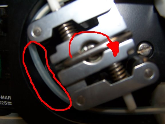
The direction of rotation was as the red arrow indicates, and you can see a void behind the roller ringed in red. The suction created caused some of the liquid in the Polyfilla to vapourise. Unsurprisingly, the stream out was very intermittent.
Then I put a pressure on the syringe (in a real design, this could easily be done with a weight):

The result was a smooth flow with no interruptions. The soft tube did tend to drift round the pump in the direction of rotation, but in a real design it should be easy to anchor.
So. Off to design an RP peristaltic pump...
Friday, March 03, 2006
New RepRap Member
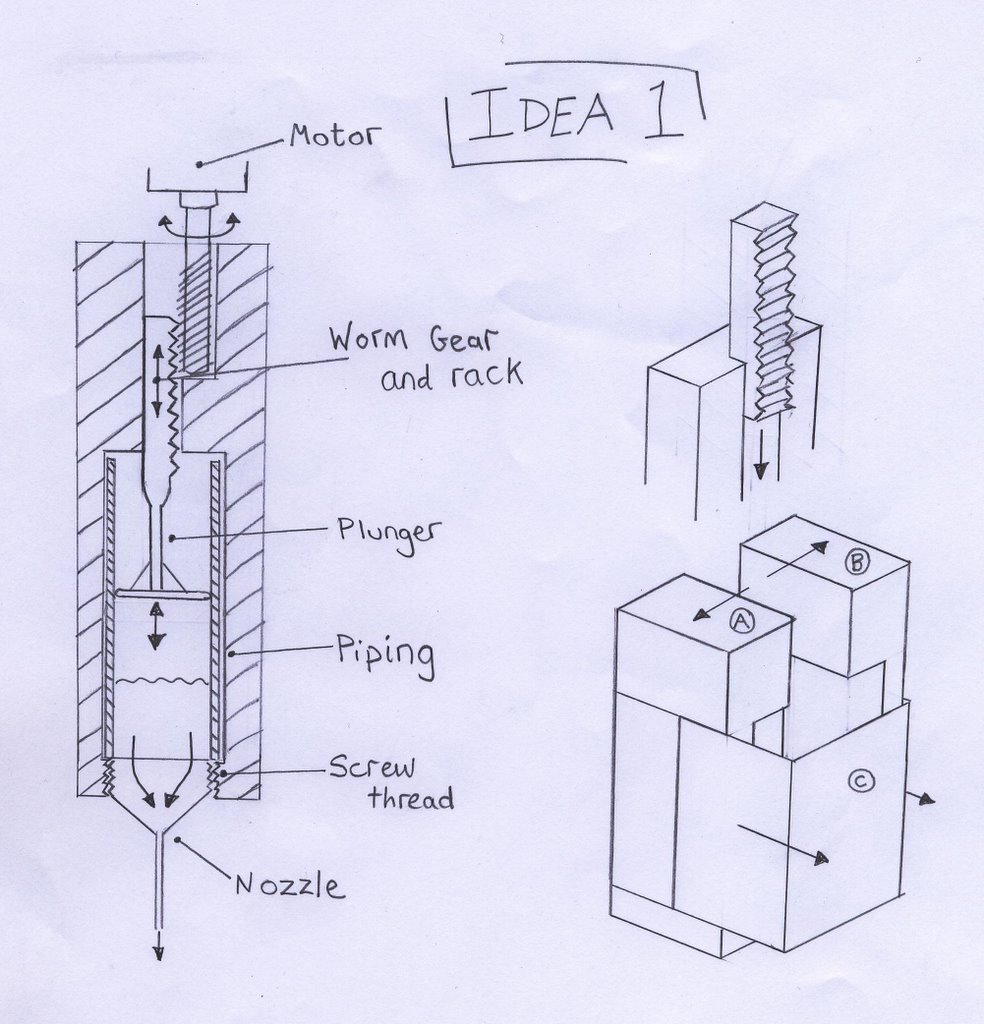
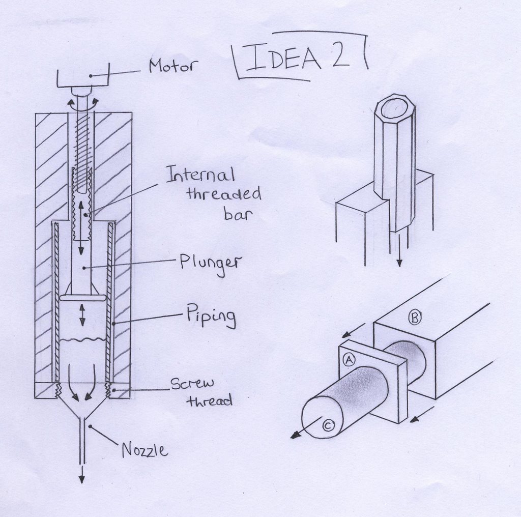
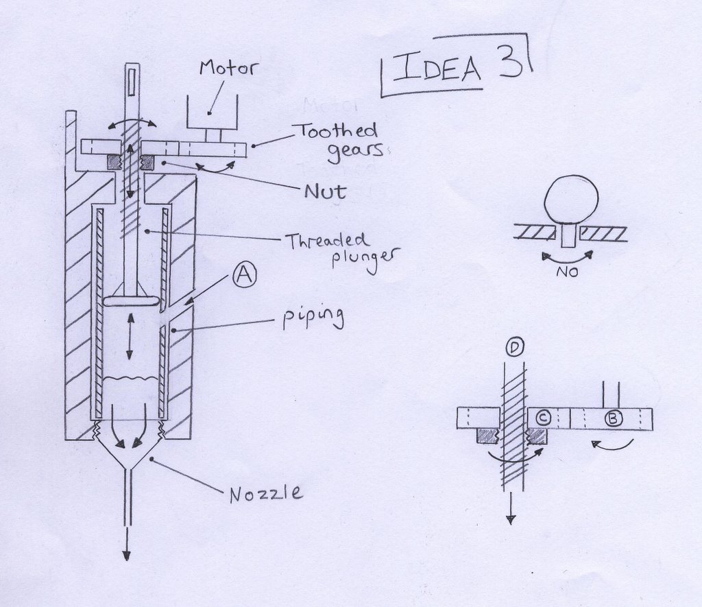
Of the three, I have decided to continue with idea 2 since it seemed the simplest and most reliable design. So now I have begun finalising the design, and will post an update when a prototype has been made and can be seen working.
Sunday, June 22, 2025
Prototype Micron Gripper (printed at macro scale)
We're starting to approach the point where it's worth considering practical things to make. Using the Blacksmith analogy, the first thing should be a micron scale gripper - essentially a pair of tongs to hold your work with.
I went for something totally minimalist. The prototype here uses a syringe body 6.5mm in diameter as a sleeve, and an actuator shaft of 4mm dia. The jaw spacing is 3mm. Here is the prototype on a 10mm grid in the open and closed configurations:

This is an ad hoc prototype so things are a bit scrappy, please excuse. The sleeve acts on the sloping arms at the base of the gripper, and a single flexure pair bends to allow the jaws to meet. By changing the length of the jaws, I can vary the range of motion.
This was printed on a Prusa Mk4. When printed on a RepRapMicron, I would use a blunt 0.5mm hypodermic needle as the sleeve, and a 0.24mm stainless steel wire as the actuator. I'm sure I'll change dimensions, but just a quick comparison. Scaling down by a factor of (6.5/0.5) 13, this would result in a gripper approximately 1.5 mm x 1.2mm which we know the μRepRap is capable of making with an accuracy of better than 50μm worst case (though the precise layer height is TBA).
The jaw spacing would be about 230μm, which is a bit small for the present capabilities IMHO but this is just an example.
Current concept is to mount it on the probe holder with a micro hobby servo to do the actuating so I don't have to put my shaky hands on it. Some support infrastructure is obviously needed but I'm nowhere near designing that yet.
To attach the gripper to the actuator wire, I would give it a light coating of UV resin before putting it in contact with the printed gripper. When it's in the right location, the resin is cured. Probably needs more contact area for the bond, and a bit more room to prevent the resin blob contacting the sleeve. This also gives a handy way to keep hold of the part when I separate it from the print bed.
Blacksmiths don't just use one pair of tongs - they have dozens. Consequently I'd expect there to be a variety of grippers. Apart from anything else I can foresee a number of them pinging off the end of the actuator wire into the universe beyond forever...
Friday, September 14, 2007
More on the granule extruder

And here it is (with the original drill) after being cut out of the mould:

I probably won't use a drill as the master finally (it's pitch is too coarse, and you have to turn it anti-clockwise, which tends to loosen things), but this shows that you can cast from virtually any helical shape to get what you want.
Labels: extruder design
Tuesday, March 06, 2007
Sebastien's polyethylene glycol

Sebastien mailed me a couple of kilos of polyethylene glycol. This is a water-soluble wax-like polymer that melts around 70oC. We have been thinking of using it as a support material.
I've been playing with it, and on its own it's much too fluid when molten - it has a viscosity similar to water. It thickens as it cools, but in order to get an extruded filament that way one would need far too fine a temperature control.
So I melted some and mixed it (2:3 by weight) with icing sugar. That makes a paste which is the ideal consistency. And it sets to a material that is like candle wax, but is water soluble (because both the sugar and the polyethylene glycol are).
I used the same trick as I used the other day to make a 3mm rod of Wood's metal - squirting it from a syringe down a 3mm silicone tube, letting it freeze, then splitting that off with a scalpel. It's a bit brittle (as you can see its broken in two). This is good for support material removal, but for other tasks it would help if it was more flexible.
I tried miking it with glycerin as a plasticiser (medically, polyethylene glycol is often mixed with glycerin), but it seemed to react with the sugar to curdle and form lumps. This itself was interesting, but not quite what I wanted. so I'll see if I can find another compound that will make it more pliable. If I can do that it will definitely go through the standard extruder.
Saturday, July 17, 2010
Mendel & multiple materials
It has always been the intention to fit a head changer to Mendel, I've had a go myself on several occasions but always ran into the same problem i.e. I haven't been able to do so without substantial modifications to the core frame of the machine unless there is a substantial loss of build volume (...I once had a design that ended up having a maximum build height of 2cm.very practical:D). Moreover, it’s more difficult to have a head changer for extruders whose designs are still in the early stages (such as the paste extruder). The main problem I suffered with is that regular designs of extruders are just too bulky without increasing the overall size of the machine, which incidentally I think is the perfect size as it is. Any bigger, and I would find it too big to find houseroom for!
Thankfully, eD had the idea of bowden extruders some time ago, which quite a few people seem have gotten work. Thus I think way forward for the time being is to implement a carriage for multiple bowden style extruders. Although this is almost certainly going to reduce build quality slightly. Some have already designed multiple bowden extruder carriages; here is my take on it:

The main differences are:
1. Support for three extruders, either bowden or paste. (limited syringe size of 10cc).
2. All the multiple head machines I've seen rely on the extruders being exactly the same height in order to get the bed clearance just right to produce good builds. I've always found getting adjusting bed clearance is tricky enough just for one extruder, and I think it's likely that there will always be a build up of tolerances that extruder heights will always change by significant magnitudes. Even still, with warping and so on in the carriage, it may still be difficult even if the extruders were identical. Thus, the carriage treats each extruder clearance like pretty much everything else on Mendel, by allowing for adjustment. All extruders are attached to a mounting plate, of which on the underside are of series three captive nuts for each extruder arranged in an equilateral triangle. Three compression springs are then placed between the plate and the extruders, and cap screws are used to adjust the compression of each spring independently. (In the picture above I’ve only used the springs on the left hand extruder, it makes sense to fix the main extruder and adjust the other two to match it)
3. In the same style as the mini carriage, the bearings are all located within the carriage itself. Having the bearings located on the outside surfaces of the carriage( like the standard Mendel design) ensures that the walls of the carriage must lie between the bearings and any extruders, eating into the working volume. However this does result in quite a wide carriage.
4. I needed to make some compromises, neither of which I'm particularly happy with, so that I don’t have to redesign the whole x-axis. Firstly the belt travels through the carriage itself on the 360 side, and secondly the belt is clamped from the inside out.
5. Finally its NOT makerbotable (its about 115 x 95mm), but it should be a fairly easy redesign to allow for only two extruders. . Even still, if you have a RepRap I'd recommend printing in PLA or using a heated bed or you'll probably run into trouble
Anyway, I’ve heavily modified the Paste Extruder, and used it in parallel with a bowden extruder I designed that based on Erik’s design but using a worm gear to do the driving (Designs to be on the SVN/thingiverse shortly). Gerrit Wyen (an intern at the RepRap Lab @ Bath Uni) created a simple script to take account of the offsets between the extruders and modify the GCode accordingly. Also Adrian has done so much I’ve forgotten exactly what he’s done, but its a lot:D. Here is a video one of the first prints; it’s a cube using PLA for the outline and top and bottom layers, and silicone sealant for the interior infill:
Whilst I did reverse the extruder to prevent ooze, and this is sufficient during a "normal build", its sat there for such a long time doing nothing whilst the paste extruder is working it still oozes horribly. For this reason I built little barrier to collect the ooze from hitting the part, but I think we may need to lower the extruder temperature a little when not in use. Anyway, here is the final part, which came out surprisingly well:

There are some more photos of the test setup and some other less successful prints here.
Labels: Bowden Extruder, extruder, multiple materials, paste extruder, x carriage
Sunday, April 06, 2008
Granule extruder
 click the pic to get one big enough to see...
A couple of days ago Zach and Nophead independently came up with two important insights. Zach's was that, in order to make a granule extruder, you don't need a complicated auger to move the granules forward; you can just use a piston, like a syringe. Nophead's was that, if you want a tube that's hot at one end and cold at the other and strong you could use stainless steel (which has a very low thermal conductivity for a metal) and slap a heatsink on it at the point where you want it to go from hot to cold.
This prompted me to sketch out the above design for a granule extruder. The extrude nozzle is on the left, made out of a brass fitting screwed to the 8mm I.D. stainless tube. We wrap nichrome heater wire round that and that end of the tube to cook them up (there would also be heat insulation round this section - not shown).
A bit to the right is the heatsink, which gives the transition from hot to cold. Around here the polymer should go from a melt to granules. This phase boundary is important, because it is here that air bubbles get more-or-less automatically excluded.
If we can easily get 8mm internal diameter stainless tube (anyone know where?), we can just use a length of the standard 8mm studding that forms Darwin's frame as the piston. The piston stays cold at all times; when it gets near the melt region (detected by an optoswitch - not shown) it is retracted and a new charge of granules falls in front of it from the hopper.
Recently Ian measured the force needed to push polymer through our standard 3mm filament extruder - it was about 10 N. This means that this device should need about 70 N to give the same pressure. The drive is a worm gear turning an M8 nut against a force transducer that measures that force.
Flow has to be controlled by force rather than the distance the piston moves, because the melting of the granules into the melt is an unpredictable process. [Also one potential problem with this design may be overrun: even when you take the pressure off, the nozzle may continue to extrude for a while.]
At the right hand end is a nut running in a hexagonal channel. This is soldered on the end of the M8 studding and stops it rotating.
I think the whole thing needs to be horizontal rather than vertical (which might be mechanically simpler) because my earlier granule extrusion experiments showed that the mere convection of heat up the tube was enough to melt the polymer all the way up. But a simple experment with a heated tube and heatsink full of non-moving granules should show if it really does need to be horizontal.
I'm off to the Go Open 2008 Conference in Oslo in a few hours to spread the RepRap word. I'm back next weekend, when - unless anyone can think of a good reason why this won't work - I might try to put one together.
I'm also experimenting with a very very simple design for a field's metal extruder for electrical circuitry that's waiting for the transatlantic postman to lay some insulated nichrome wire on me from the RRRF Store.
Watch this space for news on both when I get back.
Monday, October 23, 2006
The 'Fab @ Home' project
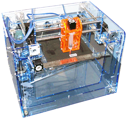
Evan Malone and Hod Lipson at Cornell have done some nice work;
They've got a syringe-based 3D printer, with full plans, up at:
http://128.253.249.235/wiki/index.php?title=Main_Page
It doesn't make copies of itself or work with thermoplastic but it's quite
impressive. The printer is made from laser cut acrylic sheet. "Approx.
$1500 RP system", according to a person who saw a talk by them.
It might be worth talking to these fellows and seeing if they would like to work together with us. I'm curious what license they're going to release his work under, what precision they're working at, and so on. They know about our project - they mention RepRap in their overview.
I think it would be extremely worthwhile to merge some of our work with
theirs, if we can sort out architectures, GPL, and so on. What do you guys think? At the very least we could use their system as a RepStrap, similar to Vik's flat-pack-RepStrap idea.
Saturday, July 08, 2006
Peristaltic pump go after all!

Gave up too soon (see blog right below)...
Jonored's neat idea (see the comments on that blog entry) prompted another experiment. Instead of having the extruder nozzle right after the pump, I put a length of the flexible tubing after it. That acts as a pressure reservoir, and evens out the flow beautifully. (The beaker of water is just so I can park the nozzle in it, turn everything off, and go for coffee without it clogging; on a RepRap machine it would probably be a piece of damp felt in the write head's parking place.)
Now, of course, turning the pump on and off doesn't turn the flow on and off - there is a huge time delay that would be impossible to allow for in software. But I already have a really simple solenoid valve design that works by pinching a soft tube like the one in the peristaltic pump. All I need to do is to install that just before the nozzle and use that to control the flow.
The soft tube swells perceptibly under the pressure. This, of course, gives a really simple way to switch the peristaltic pump on and off - just use the swelling to trip a microswitch. No computer needed...
I'm extruding "Fine Surface Polycell Polyfilla" which seems to have near-perfect characteristics for this (including being really cheap and being available at every DIY shop). Many thanks to my Final Year student James Low for all his work on that, which is really paying dividends. The syringe at the top of the picture is the reservoir of Polyfilla. An obvious design change is to junk this and just to run the peristaltic tube to the screw-on cap of the Polyfilla tube (which is like a giant tootpase tube).
Here is a shot of the bits of the pump.
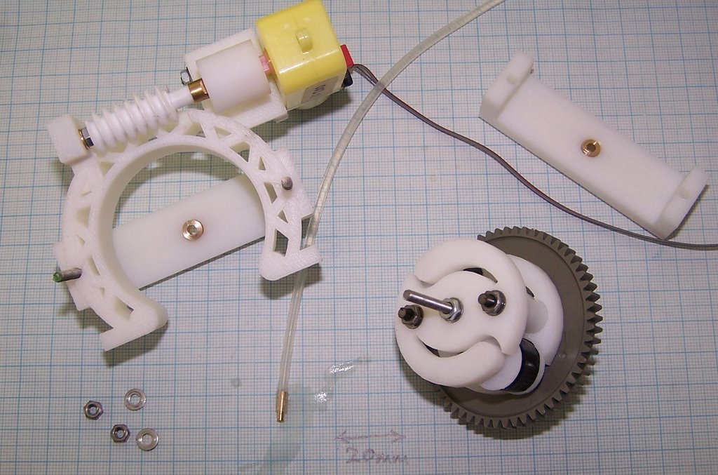
The gears are two that I happened to have lying around. But now that Vik and Forrest have sorted out how to RP gears (see here) they should be easy to replace. The nozzle is made from brass in just the same way as the bigger one on the Polymorph Extruder. Apart from those the only non-RP parts are the motor, a couple of brass bushes, and some lengths of threaded M3 bar.
It has the ability to take one or two tubes. Two tubes could be used, for example, to carry an epoxy and its catalyst. They would be mixed in the nozzle. If two different diameters of tube are used it's easy to change the volume ratio of the mix.
The nozzle could be disposable - the first thing the RepRap machine would do at the start of a build would be to make one or two new nozzles for next time...
Peristaltic pump no go
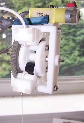
The peristaltic feeder pump for cold pastes (like Polyfilla) has a fundamental problem. Here it is working, and you can see that it produces a clean stream of paste (about 0.5 mm in diameter) at the bottom of the picture.
But the tube that forms the pump has to be flexible. This means that, when a pinch wheel goes out of contact with it, pressure is released and the back pressure from the nozzle causes the paste to rush back up the tube (which expands a little to accomodate it). So the device produces an intermittent stream - it's off half the time, and on half the time. The problem could be reduced by having more pinch wheels (my design uses two), but can never be eliminated as far as I can see. A bit of a pity, because the pump is compact and easy to make.
Back to James's driven syringe (which works...).
Tuesday, May 16, 2006
Refill of the syringe
The plumbing pipe is fixed into a carriage, and held in place with two plastic rectangular traps (which go into the two holes seen in the side of the body). The whole mechanism is allowed to swing away from the body, enabling the plunger to be removed from the piping and the piping contents (i.e. support material in the form of Polyfiller) to be replaced or refilled quickly.
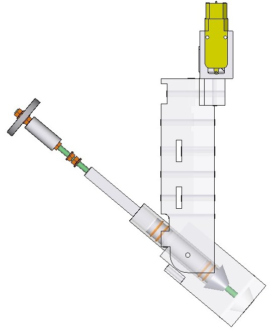
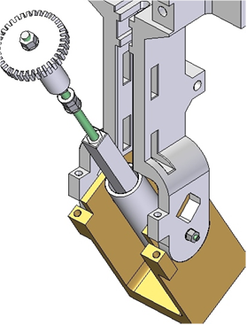

Then the mechanism is placed back into the carriage, which is locked up and the two traps slid back in place. All done in under a minute.
Support material conclusions
Having had icing sugar proposed to me as an idea I quickly found that it was unable to be deposited at 0.5mm resolution and that it took a long time to set (over 1hour).
However, Polyfiller was the perfect substance. I was able to deposit Polycell Fine Surface Polyfiller from a 0.5mm nozzle, creating a perfectly consistent line, which set hard within 2 minutes.
 An initial problem was that Polyfiller, once set, would not fully remove from the surface of an ABS part(although it would remove from the syringe nozzle if placed in warm, soapy water within an hour or so of exposure). But Adrian's use of vegetable oil as a releasing agent on the ABS cude (Blogged in April 2005) resulted in using it (veg oil) to see if it would aid Polyfiller's removal from ABS parts, which it did perfectly.
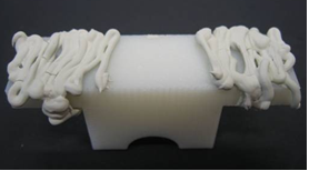 ABS part (previously coated in veg oil) covered in Polyfiller.
 The same part after the Polyfiller had been removed.
The vegetable oil was deposited as a thin layer using a brush, and it was also possible to separate Polyfiller layers from themselves. It could be best to deposit the oil from a felt tip pen, replacing the ink with oil, which could then be simply deposited as a thin layer in the FDM process.
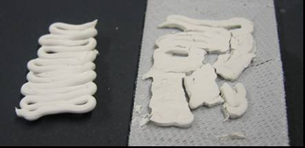
Ignore the cracked layer (it was cracked before the layers were separated).
The pictures and information regarding the deposition mechanism for the Polyfiller will be added soon (next few hours).
Monday, July 25, 2005
It is an ex-glue gun. It has ceased to be.

It is not pining for the fjords, and it wouldn't go voom if you put ... hang on, it did go >FOOOOM!< at 220V. No lab personel were injured in the explosion, though nearby an unrelated syringe was shot dead by armed police.
Vik :v)
Wednesday, June 08, 2005
Nozzle made of solder

Tests with a syringe show it squirts water in a straight, true jet. If it works with Polymorph, it'll be a very simple way of making nozzles of varying sizes. This first one will be incorporated in a Polymorph extrusion nozzle similar to the one Adrian just made, and we'll see how well it ejects Polymorph.
