Sunday, April 30, 2006
More work with the z-axis
Simon spent a bunch of time with me this afternoon getting his java stepper exerciser code working on Godzilla. It's a lot nicer than the old exerciser, loads more torque from the stepper and adjustable, too.
As mentioned in the documentation the slider for stepper speed is VERY nonlinear. From 0-240 you go up to about 1 rps. For every step above about 250 though, the stepper tries to get a LOT faster. It's kind of sad because the speeds we'd like to use run from 250-255, which means we don't have a lot of resolution. :-(
As mentioned in the documentation the slider for stepper speed is VERY nonlinear. From 0-240 you go up to about 1 rps. For every step above about 250 though, the stepper tries to get a LOT faster. It's kind of sad because the speeds we'd like to use run from 250-255, which means we don't have a lot of resolution. :-(
Thursday, April 27, 2006
Full translation on the z-axis...
I ran one of the z-axes on Godzilla for it's full range of motion, approximately 660 mm. Not as smooth or fast as I'd like, but I think I can tweak that for better performance without a lot of trouble.
Now that I have it working after a fashion some of the weight loss ideas I had for the system a few months back when I was doing design charrettes came back to me.
First off, if we fixed the threaded rod and rotated the thrust collar (nut) we could lose both the bearings and the inertia of turning the whole rod. I suspect that that would greatly reduce the torque required to move the vertical y-axis tower.
Second, if we used a cheap metal ruler on one of the z-axis stages to provide lateral stability for the y-axis towers we could lose about 75-80% of the volume of polymer needed to produce Godzilla's z-axes.
Similarly, if we used a couple of cheap metal rulers held together with reprapped clips and mountings we could provide for both lateral and vertical stability on the x-axis that is suspended between the two y-axis towers. That would drop about 75-80% of the volume of polymer needed in the x-axis.
If I went in that direction the replication time for Godzilla would drop by well over half.
Wednesday, April 26, 2006
Godzilla y-axis tower moves...
A little while ago I took a break from training neural networks to fiddle with Godzilla. I seem to be having a good day in creating ad hoc ways to make things work. A scrap of poplar wood, a C-clamp and a piece of duct tape made a workable drive nut housing for the y-axis (vertical) tower being postioned by the z-axis.
At a controller set point of 240 the tower moves very smoothly at 0.6 mm/sec with the single 754410 controller board that Simon designed. It needs to be moving 7 times faster than that for the Mk II Extruder, but never mind for now... as Galileo said, "But it does move!" :-D
The z-axis in Godzilla has far and away the highest torque requirement in the design so it looks like the NEMA 17's are going to be adequate for running Godzilla. That's a major relief!
Godzilla z-axis turns properly...
I haven't had time in some days to work at debugging the bigger NEMA 17 controller board prototype due to pressure of billable hour work.
That said, my sister was dropping by this morning and hadn't seen a NEMA 17 actually running so I cranked up the single 754410 chip board and set it to running for her. No problems.
After she left, I left it on. After a while it developed a bit of a whine with a period of about a second. It was laying on my worktable and vibrating, no big deal. The NEMA was near the back end of the z-axis stage where the threaded drive rod protrudes so I idly just let the coupling that I'd made some time ago just thread itself onto the rod and begin to turn it. At a setting of 250 (just over 1 rps) it happily turned the rod while I held the motor in my hand... for a while until the bearings got out of alignment. I tightened the bearings onto the rod and noticed that the motor nestled nicely onto the baseboard of the housing for the rear of the z-axis and at a setting of 240 ran the drive rod happily.
What I had was what amounted to a floating motor mount, something that I've been trying to design in my head for the better part of a month. The drive rod alignment is determined by the lock nuts set on the bearings. I'd been trying to create a rigid stepper mounting system and, because of my crude fabrication capabilities with the hand tools I have wasn't able to get the tolerances close enough to make things work properly.
Turns out that I didn't need close tolerances. :-D
The NEMA has about 2 degrees float in the motor mounting. With the 24 threads/inch drive rods that I'm using that means that the motor float introduces about .005 mm of periodic inaccuracy into z-axis
I think that I can live with that. :-)
I tested the thrust that the NEMA put into the drive rod by hanging onto one of the nuts I'd threaded onto it. It appears that there should be enough thrust to move the vertical y-axis stage back and forth across the work table.
I think that if I shim the threaded drive rod into the bearings with some electrical tape I should be able to get rid of most of the 2 degree float. The holes in the 3/8-in bearings are slightly bigger than 3/8-inch.
I'll try to see if I can kluge up a housing on the y-axis stage to hold the z-axis thrust nut this evening. Wish me luck.
Monday, April 24, 2006
Extruder updates
Oh, did I mention the extruder firmware problem is fixed? :) It was actually a wiring problem in my electronics, but I have discovered several other issues that I have fixed and committed.
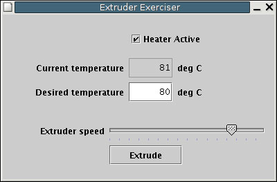 I have also committed to CVS some more work on the java drivers for the extruder. There is also a test application for extruders that you can access from the Tools menu of the RepRap application. It lets you specify a temperature and the extruder will automatically maintain that temperature. You can also drive the extruder motor.
The PIC firmware supports both "chop-chop" and dynamic heating. Chop-chop heating results in a temperature that wobbles around the target temperature while dynamic heating gives much more precise and stable heating. Currently the Java code only supports the chop-chop heating because it's a bit simpler. You need a little bit of a thermal model to make the dynamic heating work properly, so we can get to that later. The chop-chop heating doesn't seem too terrible anyway judging from my experiments with it today.
There are new preferences settings for specifying the two thermistor parameters that are needed to determine the thermistor temperature. I have also put a page on the Wiki that describes how to measure the parameters for a thermistor if they are unknown (as mine were) and how to calculate the other figure needed for the RepRap preferences (R at 0C). For more, see
http://reprapdoc.voodoo.co.nz/bin/view/Main/MeasuringThermistorBeta
Sunday, April 23, 2006
It drew a square for real!
My, how quickly I've fallen back into the swing of things after my holiday. By dangling a pen over paper on the Da Witch prototype's stage, the RepRap is now producing squares, octagons and whathaveyou quite happily and repeatably in 2D. The pen lines go over one another without deviating, so relative accuracy appears good even if absolute accuracy might need a little in the way of callibration. No photos - you know what squares look like :)
Da Witch currently constists of 3 screw-driven linear axis assemblies all made from FDM-fabricated parts: Long horizontal, vertical and a horizontal stage - no Meccano anymore. These are all driven by unipolar steppers, using a mix of 2803 and 2559 driver boards. Due to the modualrity of design, this should work just as well with the bipolar motors and 754410 driver boards - Simon plans to put a stage or two together based on those over the next week or so.
I've used "poke" scripts so far as this gives a lot of debug output when prototyping, but I will now concentrate on getting the Java code going on my setup. Once the SDCC problem in the extruder firmware is sorted, we should be up to actually making something for real. Yeah!
Vik :v)
Tuesday, April 18, 2006
RepRap application
 Adrian and I made some inroads towards merging bits of code.
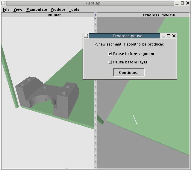
This is the current RepRap application, showing both the construction view and the production progress window. The progress area optionally allows you pause the process so you can inspect what is being printed. Throughout this time, both panels can still be fully manipulated and inspected.
What's especially fun about this is that it is all talking to the hardware now too, so you can watch the motors whirling away, changing direction, etc. as the model builds up. If only I had a frame to put it all on :)
Without the hardware installed, you can select the null device in the preferences screen and still emulate the process.
There's still plenty to do of course. As you can see, what is being produced on that screen doesn't actually match the scene on the left, and that's some of the magic that Adrian is part way through.
Sunday, April 16, 2006
RepRap Control Software
Simon and I are obviously thinking along the same lines, even though 12,000 km of molten rock and iron separate us...
I've just finished the first version of the RepRap front end that allows one to load and arrange STL files into the machine preparatory to building them. Here's a screenshot:
There are more details on the RepRap wiki here. The driver backend is being written, so when you ask the program to build the objects you've loaded it just gives an optimistic message at the moment. But I'd welcome comments on the look-and-feel.
Obviously Simon and I need to integrate his stuff described immediately below and this.
3D Progress Previewer
 While sitting in front of bad TV tonight, I had a bit of a toy with Java 3D. It's not too awful, and I ended up building a 3D progress preview window.
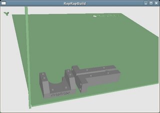
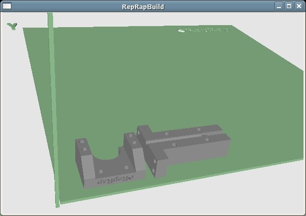
This doesn't do anything that the component Adrian is working on does, it just shows you what is printing as it prints. You can rotate, zoom and pan around the object to see it is all going as expected. More usefully, if you edit the reprap.properties file and set the geometry to "nullcartesian" it creates a dummy reprap object. This means you can fully test things without a real reprap plugged in, and it's much faster. This should be really useful for debugging. Adrian, this might be quite useful for testing the stuff you're working on too.
It's very simple to use. Here's a complete application that produced the screenshot here. This is the same 7mm square as before, rotated 45 degrees.
package org.reprap;

import org.reprap.gui.PreviewWindow;
import org.reprap.machines.MachineFactory;

public class SquareTest {

  public static void main(String[] args) throws Exception {

    Printer reprap = MachineFactory.create();

    // Comment out the following three
    // lines if you don't have java3d or don't want to preview
    PreviewWindow preview = new PreviewWindow();
    preview.setVisible(true);
    reprap.setPreviewer(preview);

    reprap.calibrate();
    reprap.selectMaterial(0);
    reprap.setSpeed(248);
    reprap.setExtruderSpeed(180);

    // Print a square, rotated 45 degrees
    reprap.moveTo(20, 5, 0);
    reprap.printTo(15, 10, 0);
    reprap.printTo(20, 15, 0);
    reprap.printTo(25, 10, 0);
    reprap.printTo(20, 5, 0);

    reprap.terminate();
  }
}
Friday, April 14, 2006
The Godzilla stepper controller board takes shape...
I got past a consulting deadline yesterday so after a good night's sleep I decided to kick back for a few hours and see if I could put together the "big board" stepper controller that I'd been thinking about. It's designed around a bus that runs across the centre of the board with the controller and comms connections in the upper right quadrant and the SN754410's in the other three quadrants.
So far I've installed two of the Sn754410's to drive one of the NEMA 17's. I plan to debug the design before trying to install the other two.
Monday, April 10, 2006
Stage now moving under Java control
I've finally got my repaired PC to run javacomm and have got the stepper exerciser running. It just drives the stage module at the moment, though I plan to add the rest on tonight. This puts the hardware only a whisker away from being capable of producing a plotted circuit board, provided the hardware actually checks out.
The stepper driver being used is the ULN2803-based design, driving a unipolar stepper motor. I'll work on the updated instructions over Easter when I'm not allowed in the workshop...
The 754410-based extruder controller design is also communicating, and can control the motor and read values from the thermistor. A glitch in the driver code (possibly a compiler issue) is currently preventing the use of the heater controller, but as I have a working thermostat from the prototyping stage this is not a show-stopper.
Vik :v)
Sunday, April 09, 2006
ARNIE Mk1 first build
So this is what he looks like in the flesh!
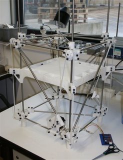
It's very satisfying to point out that everything white is RP. But annoying to note that he doesn't quite work yet. He'll go down beautifully. But not up. But that was the very first impatient test without bothering to align the bearings properly, so I'm keeping my well and truely fingers crossed for next week.

It's very satisfying to point out that everything white is RP. But annoying to note that he doesn't quite work yet. He'll go down beautifully. But not up. But that was the very first impatient test without bothering to align the bearings properly, so I'm keeping my well and truely fingers crossed for next week.
Stripboard extruder controller

I thought I better build one of these since my previous versions have only been on breadboards. This is a slightly more compact layout than the one on the wiki (the variation is in CVS). It's probably better in general to stick to the larger design on the Wiki, but I'm fussy and don't like big boards.
All working nicely so far. Now that I have a real one I should do some more work on the Java drivers for it.
Saturday, April 08, 2006
Still Life With Stepper Controller Board and Stepper Motor....
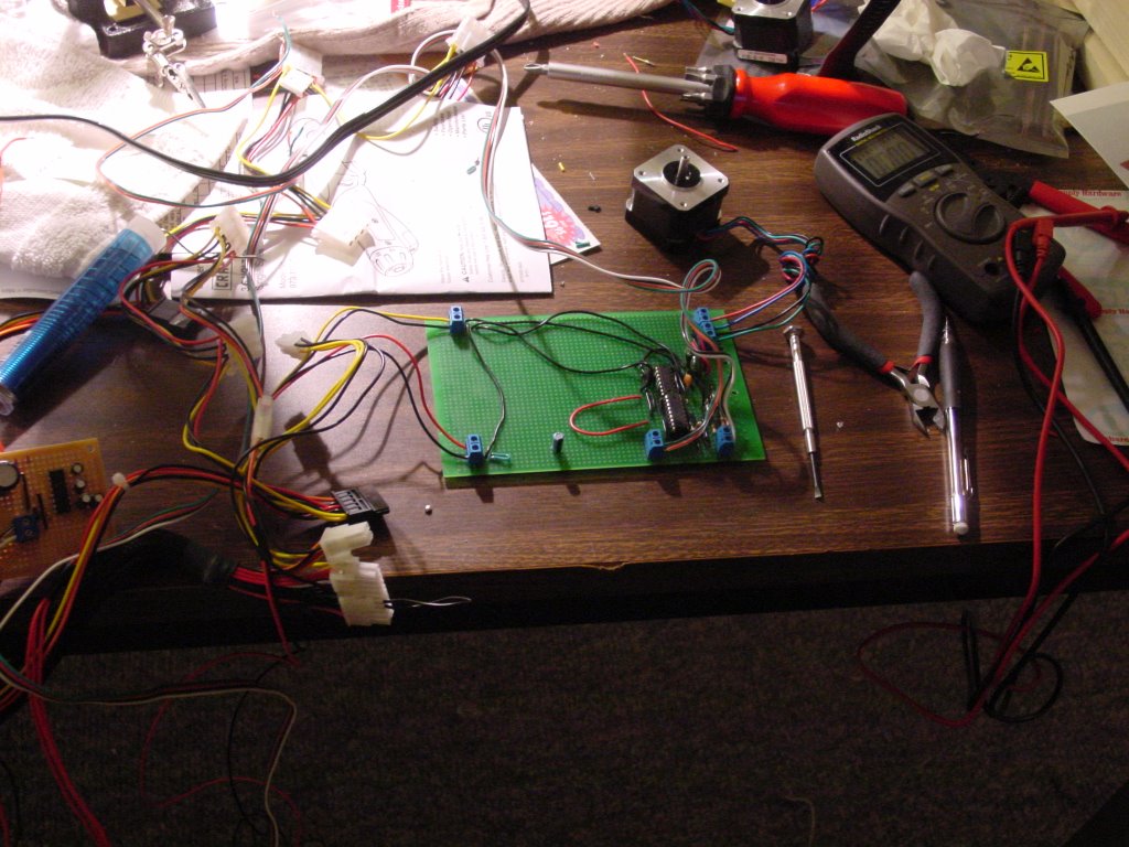 It works now...
After Simon published the debugging protocol in the wiki I decided that I had better regularise my handling of connections to the stepper motor. To that end I installed two screw terminals to handle the connections rather than the direct to motor soldering that I had done earlier.
I was a good boy and walked through Simon's test series for voltages before trying to run a stepper motor. Everything checked out perfectly with ~10.75v being sent to the stepper motor.
Just for luck I hooked up a different NEMA 17 than I had used earlier for the test. That stepper motor turned quite nicely. That SN754410 chip doesn't get half hot! You could cook breakfast on it! :-o
I tested the board for speed and direction and it seemed to respond perfectly.
After satisfying myself that the board worked properly, I swapped stepper motors for the old one. After doing that the whole system froze. It stayed frozen when I disconnected the stepper motor and restarted the exerciser programme. At that point I decided that hot swapping the stepper motors was a bad idea and that I must have fried the board doing that.
I disconnected the stepper board and hot wired the token ring on the comms board and still not even that worked. Hyperterminal wouldn't even echo. It struck me that I couldn't have fried the comms board too so I crawled under my worktable and checked the serial connector and discovered that the pin 3 comms line had broken free.
I resoldered that and resolved to put a housing on the connector in the morning and then went back and checked out both the first and second stepper motors on the comms board after extablishing that both comms board and the stepper board weren't misbehaving in any way.
Both ran nicely.
As hot as that SN754410 chip got I wonder about the sense of stacking them. It also strikes me that on a practical board they need to be spaced out away from the PIC16F628 and from each other and good heat sinks glued to them if we are going to run steppers driving a reprap for long periods of time.
Those are details, though. That's just tweaking, something that I am in a good position to do now that I have a working design. Many thanks go to Simon and Vik for the design and realisation of the bipolar stepper controller board and associated firmware. Well done, guys!
Customisable addresses etc

I have added a settings screen to the main RepRap application. This now lets you set addresses for each of the motors as well as the current limits. You can set the serial port in here too, so no need to edit properties files manually any more. It's kinda minimal but handy.
The next cool thing to do will be to integrate what Adrian is doing into the main app.
Tuesday, April 04, 2006
First try at a stepper controller for Godzilla...
LOL! Well, once again I begin to strongly suspect that there must have been fine jewelry makers in both Vik and Simon's ancestry while my own must have been lucky to hang onto a hammer with both hands. :-s
Last night I began trying to build Simon's beautiful, tiny stepper layout on a euroboard. I figured that it would be easy enough to just lay his slave board further down the euroboard instead of using that nice amp connector which I don't have in-hand. The remainder of the evening and early morning here was punctuated by a series of dimunitions in my expectations for how far along I expected to get. :-(
My first downgrade in expectations occurred when I had a close look at the pic of the master board where Simon had stacked two 754410's. I had always been a bit suspicious about whether stacking chips like that was a good idea. Looking closely at the quality of soldering of the two chips' pins together put a whole new light on the matter, however. Not to put too fine a point on it, Simon's usually beautiful soldering work looked nasty on that particular bit of the master board. It didn't take a great stretch of imagination for me to draw the conclusion that if Simon's usual impeccable soldering work suffered that badly on that kind of stacking that my own would be so bad as to make the task totally impossible. :-(
Okay, not a problem. So my first attempt at a stepper board would have two, unstacked 754410's instead of four 754410's stacked in two modules. Who knows, maybe Godzilla wouldn't require the torque that four would allow. :-D Mind, I'd already halved the torque by going for 12v and halved it again by having the 754410's. Not to worry, though. The exercise could be a concept proving one rather than an end product. I'd have learned a lot about stepper boards even if I didn't get a finished product the first time out. These are early days for repraps, after all. :-)
The next expectation to fall by the wayside was putting the slave board on the euroboard first time out. It wasn't impossible, mind, given my modest skills. It was just adding complication and expense to an exercise that was going to be hard enough for me to accomplish in the first place.
As I began to lay out that minor mare's nest of jumpers that looked so reasonable in Simon's pics I began to realise that I was in the middle of another JDM programmer board nightmare. The clearances and tolerances for those jumper paths were simply more than my poor motor control skills and fingers could cope with. I didn't want to junk the board though and get a bigger one for this exercise like I did with the JDM board. Simon's design looked considerably less difficult that the JDM in a lot of ways, so I soldiered on.
One thing that made things easier was dropping the self-imposed requirement that connecting jumpers had to be flat with the board's surface. That made making the connections much, much easier and sped the work up dramatically.
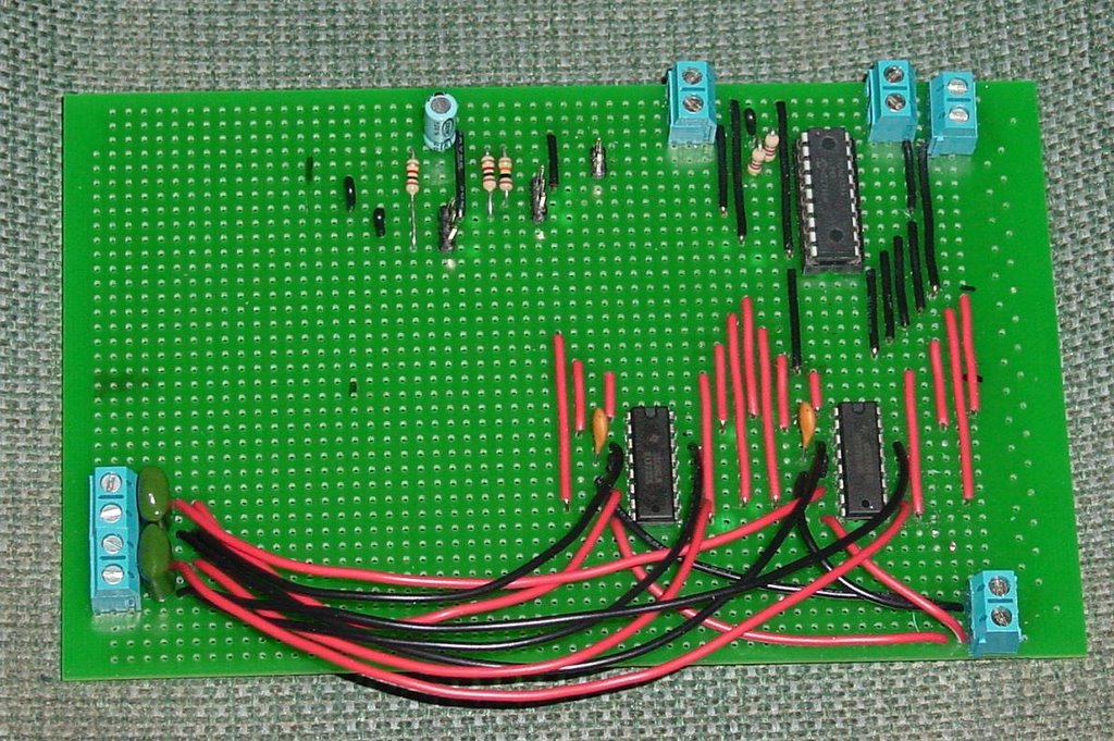
Right now, the stepper board is done except for the wireout to the NEMA 17, seating the PIC16F628 and that capacitor between ground and the 5v power supply that isn't shown thus far on the schematics that keeps the electromagnetic noise from the steppers running from getting into the control circuitry.
I'm staying with the two pin screw terminals approach that separates power from communications. The serial comms ports are the two terminals on the top, left hand edge of the board.
The 5v supply is at the top, right of the board with ground at the top and 5v at the bottom side of ther terminal. The 12v supply is at the bottom, right of the board with ground at the top side of the terminal and 12v at the bottom.
I've run jumpers directly from the 12v supply to the ground and 12v power supply points on the 754410 rather than depending on the strips to carry that current. I also ran a jumper from the ground on the 12v supply to the ground on the 5v supply. I've still got to put a jumper to connect up the power and comms grounds.
With a little luck this board should allow me to get a NEMA 17 running without a lot of drama. Then I can work up to more complexity form there. :-)
Last night I began trying to build Simon's beautiful, tiny stepper layout on a euroboard. I figured that it would be easy enough to just lay his slave board further down the euroboard instead of using that nice amp connector which I don't have in-hand. The remainder of the evening and early morning here was punctuated by a series of dimunitions in my expectations for how far along I expected to get. :-(
My first downgrade in expectations occurred when I had a close look at the pic of the master board where Simon had stacked two 754410's. I had always been a bit suspicious about whether stacking chips like that was a good idea. Looking closely at the quality of soldering of the two chips' pins together put a whole new light on the matter, however. Not to put too fine a point on it, Simon's usually beautiful soldering work looked nasty on that particular bit of the master board. It didn't take a great stretch of imagination for me to draw the conclusion that if Simon's usual impeccable soldering work suffered that badly on that kind of stacking that my own would be so bad as to make the task totally impossible. :-(
Okay, not a problem. So my first attempt at a stepper board would have two, unstacked 754410's instead of four 754410's stacked in two modules. Who knows, maybe Godzilla wouldn't require the torque that four would allow. :-D Mind, I'd already halved the torque by going for 12v and halved it again by having the 754410's. Not to worry, though. The exercise could be a concept proving one rather than an end product. I'd have learned a lot about stepper boards even if I didn't get a finished product the first time out. These are early days for repraps, after all. :-)
The next expectation to fall by the wayside was putting the slave board on the euroboard first time out. It wasn't impossible, mind, given my modest skills. It was just adding complication and expense to an exercise that was going to be hard enough for me to accomplish in the first place.
As I began to lay out that minor mare's nest of jumpers that looked so reasonable in Simon's pics I began to realise that I was in the middle of another JDM programmer board nightmare. The clearances and tolerances for those jumper paths were simply more than my poor motor control skills and fingers could cope with. I didn't want to junk the board though and get a bigger one for this exercise like I did with the JDM board. Simon's design looked considerably less difficult that the JDM in a lot of ways, so I soldiered on.
One thing that made things easier was dropping the self-imposed requirement that connecting jumpers had to be flat with the board's surface. That made making the connections much, much easier and sped the work up dramatically.
Right now, the stepper board is done except for the wireout to the NEMA 17, seating the PIC16F628 and that capacitor between ground and the 5v power supply that isn't shown thus far on the schematics that keeps the electromagnetic noise from the steppers running from getting into the control circuitry.

I'm staying with the two pin screw terminals approach that separates power from communications. The serial comms ports are the two terminals on the top, left hand edge of the board.
The 5v supply is at the top, right of the board with ground at the top and 5v at the bottom side of ther terminal. The 12v supply is at the bottom, right of the board with ground at the top side of the terminal and 12v at the bottom.
I've run jumpers directly from the 12v supply to the ground and 12v power supply points on the 754410 rather than depending on the strips to carry that current. I also ran a jumper from the ground on the 12v supply to the ground on the 5v supply. I've still got to put a jumper to connect up the power and comms grounds.
With a little luck this board should allow me to get a NEMA 17 running without a lot of drama. Then I can work up to more complexity form there. :-)
STL files and polygons
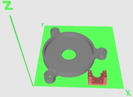
Thanks to Daniel Selman's Java3d book I have got a program working that will load STL files and allow one to zoom, pan and rotate them on the screen. It has a stylised view of the working volume of the RepRap machine (green), into which one can load objects to be made (Vik's spider - grey; and my extruder motor holder - pink). The working volume is represented by an STL file too, so we can make it look like anything we like (and animate bits of it if we really need to). The parts for manufacture are all grey at the start; the pink is just me testing if my code to pick them with the mouse works.
I now need to write the code that allows one to move the picked object about on the green square of the build-base to position it where you want it made, and to do collision detection to make sure objects don't touch.
I also have polygon infill working for laying down CAPA by the extrude head. One would outline a part slice with polymer extrudate, then offset that shape inwards by the width of the extrudate and hatch fill it like this (this is not one of the parts above):
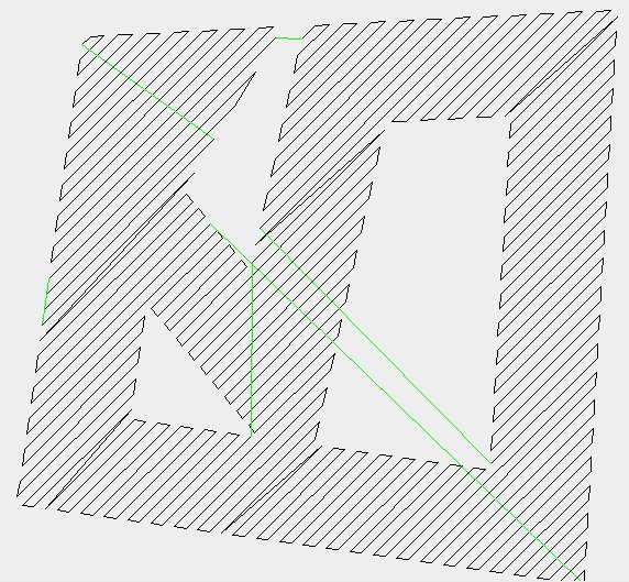
The black lines are fill; the green ones are jumps. The slightly odd diagonal lines between adjacent passes will go when I have the next stage working (they are caused by the algorithm's absolute refusal to put material where there should be air, even if it's within the tolarance of a surface).
I need to get set-regularization working for the polygons (lots of coincident surfaces get unioned when an object has vertical sides), then put the 3D stuff and the polygons together...
Monday, April 03, 2006
Godzilla comms board is operational...
After a few false starts this morning I got the comms card for Godzilla working. It is echoing properly both with hyperterminal and the VB.NET serial comms test programme.
The board takes on 5v power directly from the power supply and does not have any 12v current moving on the board.
Connections with the rest of the system are via 2 pin screw terminals. No power is carried in the comms cable. The PC serial port connection is wired directly into the board.
Now I can start building up a stepper controller with confidence that I have something to connect it to. :-)
Sunday, April 02, 2006
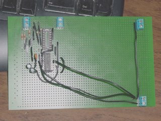
Slave board built
This is what the stripboard bipolar controller slave board currently looks like. The larger of the two boards is the master controller. Each board drives one motor, and these can be chained together as needed for the number of motors required. This is used in cases where multiple motors must be driven for the same axis in exact synchronisation.

Also note the stacked/piggybacked 754410's on the master (click for close-up image). The slave doesn't have the extra 754410 yet because I've run out. I still have to add heatsinks to both too.
More details on the wiki
Also note the stacked/piggybacked 754410's on the master (click for close-up image). The slave doesn't have the extra 754410 yet because I've run out. I still have to add heatsinks to both too.
More details on the wiki
![]()