Tuesday, April 04, 2006
First try at a stepper controller for Godzilla...
LOL! Well, once again I begin to strongly suspect that there must have been fine jewelry makers in both Vik and Simon's ancestry while my own must have been lucky to hang onto a hammer with both hands. :-s
Last night I began trying to build Simon's beautiful, tiny stepper layout on a euroboard. I figured that it would be easy enough to just lay his slave board further down the euroboard instead of using that nice amp connector which I don't have in-hand. The remainder of the evening and early morning here was punctuated by a series of dimunitions in my expectations for how far along I expected to get. :-(
My first downgrade in expectations occurred when I had a close look at the pic of the master board where Simon had stacked two 754410's. I had always been a bit suspicious about whether stacking chips like that was a good idea. Looking closely at the quality of soldering of the two chips' pins together put a whole new light on the matter, however. Not to put too fine a point on it, Simon's usually beautiful soldering work looked nasty on that particular bit of the master board. It didn't take a great stretch of imagination for me to draw the conclusion that if Simon's usual impeccable soldering work suffered that badly on that kind of stacking that my own would be so bad as to make the task totally impossible. :-(
Okay, not a problem. So my first attempt at a stepper board would have two, unstacked 754410's instead of four 754410's stacked in two modules. Who knows, maybe Godzilla wouldn't require the torque that four would allow. :-D Mind, I'd already halved the torque by going for 12v and halved it again by having the 754410's. Not to worry, though. The exercise could be a concept proving one rather than an end product. I'd have learned a lot about stepper boards even if I didn't get a finished product the first time out. These are early days for repraps, after all. :-)
The next expectation to fall by the wayside was putting the slave board on the euroboard first time out. It wasn't impossible, mind, given my modest skills. It was just adding complication and expense to an exercise that was going to be hard enough for me to accomplish in the first place.
As I began to lay out that minor mare's nest of jumpers that looked so reasonable in Simon's pics I began to realise that I was in the middle of another JDM programmer board nightmare. The clearances and tolerances for those jumper paths were simply more than my poor motor control skills and fingers could cope with. I didn't want to junk the board though and get a bigger one for this exercise like I did with the JDM board. Simon's design looked considerably less difficult that the JDM in a lot of ways, so I soldiered on.
One thing that made things easier was dropping the self-imposed requirement that connecting jumpers had to be flat with the board's surface. That made making the connections much, much easier and sped the work up dramatically.
Right now, the stepper board is done except for the wireout to the NEMA 17, seating the PIC16F628 and that capacitor between ground and the 5v power supply that isn't shown thus far on the schematics that keeps the electromagnetic noise from the steppers running from getting into the control circuitry.
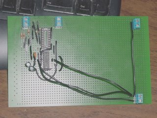
I'm staying with the two pin screw terminals approach that separates power from communications. The serial comms ports are the two terminals on the top, left hand edge of the board.
The 5v supply is at the top, right of the board with ground at the top and 5v at the bottom side of ther terminal. The 12v supply is at the bottom, right of the board with ground at the top side of the terminal and 12v at the bottom.
I've run jumpers directly from the 12v supply to the ground and 12v power supply points on the 754410 rather than depending on the strips to carry that current. I also ran a jumper from the ground on the 12v supply to the ground on the 5v supply. I've still got to put a jumper to connect up the power and comms grounds.
With a little luck this board should allow me to get a NEMA 17 running without a lot of drama. Then I can work up to more complexity form there. :-)
![]()