Thursday, December 29, 2005
Welding Rig Arrives!
My cheap Chinese 120 amp welding rig arrived today. The mask was the worse for wear so I acquired a new one locally along with 2 mm welding rods so that I can get a decent duty cycle out of the dinky thing and leather gauntlets. I plan on doing some practice welds tomorrow before working on the extruder frame. Wish me luck.
Wednesday, December 28, 2005
3D Cartesian axis, take 1
With a fair bit of help from Ash, I've combined the Meccano, FDM and bolts approaches to come up with a functional 3D Cartesian axis. No end-stops yet, and haven't powered all motors simultaneously yet. But definitely all headed in the right direction. The top stage sits on 4x M6 150mm bright plated bolts and there's quite a bit of polycaprolactone involved:

Please excuse the mess in the background. We're still recovering from giftmass and my Brother-in-law seems to have neglected to take Rebecca or Laura back with him. They are taking an interest in Uncle Vik's experiments and are making references to "Dexter's Lab", whatever that might be. For reasons I fail to understand this involves them stealthily turning the machine on while vital parts are not in place, or are hardwired to inopportune settings.
Vik :v)
Friday, December 23, 2005
Polymer needed
Something that the RepRap project could do with is a thermoset resin that will go up
to 200 - 250 C. That way we'd be able to create moulds by RepRap for
high-temperature parts and make them at room temp. But all the everyday (i.e.
cheap...) thermosets that I can find flake out around 170 C.
Does anyone have any suggestions?
to 200 - 250 C. That way we'd be able to create moulds by RepRap for
high-temperature parts and make them at room temp. But all the everyday (i.e.
cheap...) thermosets that I can find flake out around 170 C.
Does anyone have any suggestions?
Vertical platform successful test - 500g+
I'm pleased to report that the vertical axis is performing well in the testbed, and can carry a load in excess of 500g smoothly up and down. When things quieten down a bit - I've got the family around - I'll get cracking on the stage axis.
But now I sign off for the next few days of Christmas fun, and wish all a Merry Christmas, Frohe Weihnachten, or whatever variant of the solstice festival lights your festive candle.
Vik :v)
But now I sign off for the next few days of Christmas fun, and wish all a Merry Christmas, Frohe Weihnachten, or whatever variant of the solstice festival lights your festive candle.
Vik :v)
Tuesday, December 20, 2005
Heat Testing the Extruder Assembly...
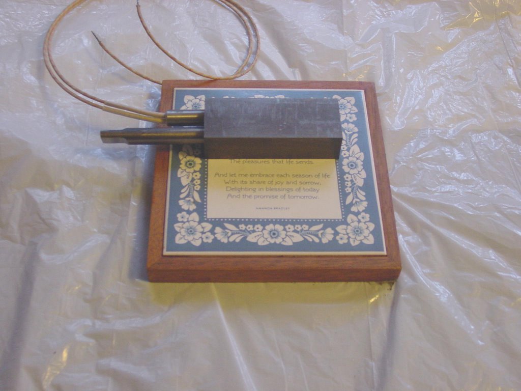 I looked after several small but important jobs on the filament extruder today with the grinder. First was prepping the end of my bar of 1x1-1/2 inch cross-section bar so that I can cut a new guide block for the extruder piston.
More importantly, I ground down the end of the piston as you can see in the photo so that it can be attached to the injector handle of the system. I got it to .001 inch tolerance which is not so bad with a grinding wheel.
Finally, I heat tested the assembly to 220 degrees Celsius to see if expansion was going to cause binding in either the piston or the cartridge heater. Although the piston fits quite tightly in the extruder cylinder there was no heat expansion binding and the cold cartridge heater was readily able to fit into its slot.
There are a few extra bits of assembly to be done but I will be putting those off until my welding rig arrives. After that all that remains is to wire up the heating circuit and we are good to go.
Monday, December 19, 2005
Progress on the filament extruder...
Just to keep everybody in the loop on the filament extruder project, the heavens opened yesterday and we got about 75 mm of rain so I stayed in for Sunday rather than trekking out to my brother-in-law's workshop in Carmel Valley. I also found myself facing the old maxim that says that the first 90% of a project takes 90% of the time and the last 10% takes 90% of the time.
I have to cut a new piston alignment block, buy a rat-tailed file to sort out a bolt connection hole in the frame that slipped while I was drilling it with the drill press and finally make another expedition to the hardware store to get a few drills and threading taps that I hadn't bought before.
A trek to the electronics supply shop across the peninsula to buy some ceramic wire nuts, a circuit fuse holder, an indicator light, a length of power cord and a plug is also on today's schedule. This thing has a lot of bits.
I will also be buying a half-inch threading tap to see if it is feasable to use a brass plumbing plug for the extruder die. That will mean that I can screw into the extruder block rather than brazing it in as per the plans. If that works I can swap out extruder dies instead of having to make a new block and heater cartridge for each time I want to make a different diameter filament. After having drilled one of those blocks I am not anxious to have to make them as a regular occupation with the WWII era Navy drill press that I have.
Meccano on steroids...
Doing some web searching I ran across this little company in southern California...
http://smi4motion.com
They sell bits, subassemblies and complete positioning systems. Their catalog...
http://smi4motion.com/2Products/PDF/SMI_General_Catalog_1.02.03.pdf
...is a fun read. As is their price list.
http://smi4motion.com/price_book.htm
http://smi4motion.com
They sell bits, subassemblies and complete positioning systems. Their catalog...
http://smi4motion.com/2Products/PDF/SMI_General_Catalog_1.02.03.pdf
...is a fun read. As is their price list.
http://smi4motion.com/price_book.htm
Sunday, December 18, 2005
Central core of vertical axis ready
I've assembled the central core of the vertical axis. The 4mm bracing was needed, and stabilises the design beautifully:

All we need now are the electronics to drive the stepper motor (currently on a breadboard) and the carriage FDM component. Then the vertical axis can join the linear axis.
For those pondering how it works, the four inner rods are just bracing. The three outer rods are connected to the large gear wheels like this:

When the motor goes round, a pinion gear on it drives the big gear wheels. These rotate the 3 larger threaded rods. The whole assembly is suspended from the three nuts on those rods. The nuts are held still, and the whole mechanism moves up or down depending on which way the 3 rods are rotated.
A turntable or stage will be attached to the top of this assembly.
Vik :v)
All we need now are the electronics to drive the stepper motor (currently on a breadboard) and the carriage FDM component. Then the vertical axis can join the linear axis.
For those pondering how it works, the four inner rods are just bracing. The three outer rods are connected to the large gear wheels like this:
When the motor goes round, a pinion gear on it drives the big gear wheels. These rotate the 3 larger threaded rods. The whole assembly is suspended from the three nuts on those rods. The nuts are held still, and the whole mechanism moves up or down depending on which way the 3 rods are rotated.
A turntable or stage will be attached to the top of this assembly.
Vik :v)
Saturday, December 17, 2005
Ready for the drill press...
The Gingery design has detailed instructions about where you have to drill holes so that the steel parts can be bolted together. Fortunately, I remembered a little trick my father, who used to run an ordinance and repair depot for the Army, once told me about. Simply said, you use c-clamps to assemble the parts into their final form and then put the assembly under the drill press, removing one clamp at a time and drilling the holes for the connecting bolts through both members at the same time. Doing that is about ten times faster and a lot less error prone than drilling and afterwards assembling the parts.
I am also going to take a first run at drilling the extruder block for the piston and heater cartridge. Wish me luck on that. I've never tried to drill an accurate hole through four inches of hard steel in a close tolerance situation.
Friday, December 16, 2005
Screw-driven axis self-callibrates
Here is the fabricated screw-driven axis, with the old Meccano carriage sitting on it. I've put the spider on top of the carriage so you can see roughly where things are going to sit:

The limit switch is not fitted in this photo - I need to drill a couple of small holes when I figure out exactly where they need to be - but when it is taped in place the carriage self-callibrates and returns to its default position.
The axis itself has 23 components, including every nut, bolt and washer.
Vik :v)
Jigging the Filament Extruder Frame...


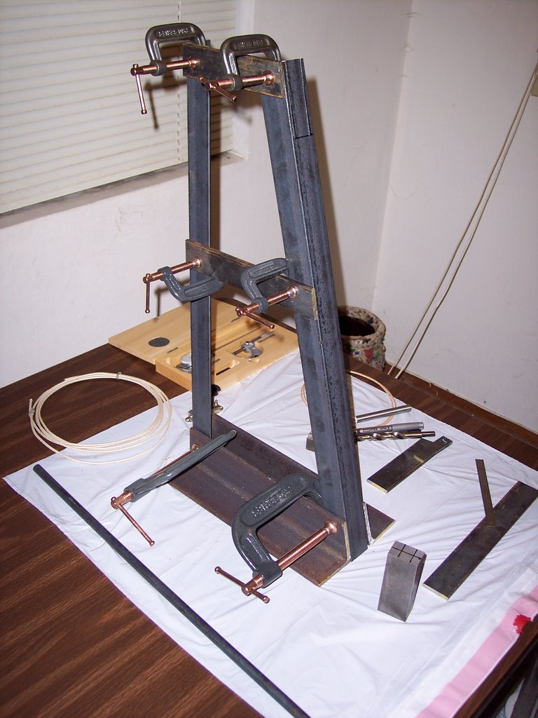
I bought a couple of C-clamps this morning and began to jig the frame parts together. There is still quite a bit of cutting to do but the device is beginning to take shape. The big question now is whether I should just buy a half dozen smaller C-clamps and weld everything together save the extruder or stick to the Gingery design and use both bolts and welds. I suppose that if I want to tear it down and salvage the steel later the bolts plus welding would be the best bet.
Sawing off the extruder block proved to be less of a challenge than I had originally thought. I am going to drill it out this weekend. The drill press I have has no positioning vice so I have cobbled together a frame from some 3/16x2-1/2x2-1/2 angle iron and my C-clamps which should stabilise it on the drilling table quite nicely. I was worried that selecting a 1/2 inch diameter cartridge heater would cause me to have to realign the injector chamber. That has not proved to have been a problem, however.
Thursday, December 15, 2005
Strange Economics...
The Gingery design for the filament extruder depends on about 10 centimetres of arc welding rather than crossbracing to keep its frame rigid. I called a tool rental agency and discovered that renting a light welding rig for a day would cost me about $100. Using Froogle I discovered that I could buy a complete light duty rig with accessories for $85, shipping included. It will arrive either Saturday or Monday. My brother-in-law said that it can live at his house.
Screw-driven axis under construction
Here's a shot showing the bearing assembly under construction. The large rectangular part is the rail clamp for the screw-driven linear axis:

I got this rotating smoothly last night, but I've had an idea on how to simplify it further so no complete photos yet.
Also in the image are the spiders and gears. They're only held in place with bolts at the moment so I could check the spacing on the gears. It looks good.
The rail clamp itself is probably best split into 2 parts to simplify construction, the bolt holes need shaping so they are RepRap friendly, and the clamp surfaces could probably be about 0.2mm further appart. Other than that (and the hole I poked in my finger with a chisel) I'm very happy with the results so far. Next, I eagerly await the carriage component. Once we find out how much loading this can take in the real world, we'll have an idea on how large a mechanism we can fit on top of the vertical axis.
Oh, Austria Microsystems supplied 4096-step magnetic rotation sensor samples, including a prototyping board. These folks really know how to provide sample kits - I'm very impressed. If anyone wants to work in interfacing these to a PIC, do speak up:
http://www.austriamicrosystems.com/03products/products_detail/AS5045/description_AS5045.htm
Vik :v)
Wednesday, December 14, 2005
Cartridge heater arrives!
The 120 volt, 300 watt cartridge heater that will be seated in the extruder block arrived just now. You would easily mistake it for a blasting cap except that the lead wires are too heavy duty. Everything needed to make the filament extruder is either on my worktable or in the nuts and bolts section of my local hardware store.
Building the filament extruder version 1.0


We collected the steel for the extruder too late to do anything with it yesterday. This morning I acquired a small mitre box and some fresh hacksaw blades and spent the rest of the day cutting the big chunks of steel bar and angles into smaller ones as per the design specifications. Tomorrow, after cutting the few remaining bits save the extruder block, I will round off the edges and corners with a grinder and, with a bit of luck, drill the holes for the bolts used to put it all together.
I also discovered that you do most definitely not put steel fresh from the steel yard onto a carpet.
Tuesday, December 13, 2005
Clamps & spider arrive
The FDM'd clamps and spider turned up in the post. I spent last night picking the support material out from the gaps - I'll have to refine the clamp design, as there are a lot of fiddly nooks and crannies filled with support material. Still, the holes are the right size and in the right places.
I found the best tool for extracting the material from big, flat areas was a 1 inch wood chisel, flat side against the plastic you want to keep. It fairly rips through. Pokes deep holes in fingers too, damnit.
For slots, a craft knife works well, and for awkward areas I used a cobbler's awl. To clear out bolt holes. I "wood-pecker" drilled using a Dremmel with a 2.5mm bit, then punched out the remains with a screwdriver. My original plan of using a router bit on the Dremmel was a compete non-starter and my water-blaster won't shift the support material at all.
If there's one thing I've learned so far, it's not to design intricate little crevices that get filled with support material.
Vik :v)
Tuesday, December 06, 2005
Polymorph and polycaprolactone
I have now obtained a sample of polycaprolactone granules and used it in place of Polymorph. It works perfectly to make rods for the RepRap extruder. I used granules of CAPA 6800 polycaprolactone (2-Oxepanone, homopolymer; molecular weight 80,000, CAS number: 24980-41-4) from
 Solvay Interox Ltd.
Baronet Works
Lower Walton
Warrington WA4 6HB
U.K.

+44 (0) 1925 643210
The Solvay website is here. CAPA 6800 is supplied by the company in 20 kg paper sacks, or 500 kg bags.
There is a more complete write-up on polymorph on the RepRap Wiki.Thursday, December 01, 2005
Our Carriage Awaits.
Here's a model of the carriage assembly that works on a piece of M5 studding. This will carry the gear assembly, in turn held by an orange spider at the top and bottom:

I'm uploading the AoI source files to the Wiki now.
Vik :v)
I'm uploading the AoI source files to the Wiki now.
Vik :v)
![]()