Thursday, June 26, 2008
RepRap At OSCON 2008

The RepRap Child is heading for OSCON in Portland, Oregon (yes, I'm off to the US of A again). I'm presenting in the last session on Thursday afternoon and will probably set up an impromptu display in the foyer if I can get away with it, so pop in and say "Hi" if you're in the neighbourhood.
Vik :v)
Wednesday, June 25, 2008
Measuring extruder temperature using Adrian's circuit
I prototyped and tested Adrian's proposed circuit for using the resistance of the Nichrome 60 heater on Tommelise's extruder barrel to measure its temperature... read more
Friday, June 20, 2008
New Board: Opto Isolator v1.0
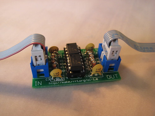
I'm proud to announce a new board today, the Opto Isolator v1.0. The opto isolator board is an accessory board that will make your electronics safer, contain less noise, and more reliable. An opto isolator is something that isolates 2 circuits electronically, while allowing you to pass signals through. It can protect against power spikes, as well as preventing noise (say from a motor) from passing through to your Arduino. The circuit itself is based on 2 of the HCPL2631 chips providing a 4-channel opto isolator capable of up 2.5kv of isolation, and 10Mbit/sec data transmission. Plus, its a beautiful and symmetric board, not to mention our first RepRap board to use super-awesome IDC headers. Yay!
Check out the full-on documentation today, or pick up a kit from the RRRF.
Wednesday, June 18, 2008
Line buffering in the Arduino
Arduino line buffering from Adrian Bowyer on Vimeo.
I have implemented a poly-line buffer in the Arduino code. This means that, when the host software wants to plot a polygon, it doesn't have to wait till one line segment is finished before sending the next. It can just blast them at the Arduino as fast as it likes (it gets stopped when the buffer is full...) and, more importantly, the Arduino always has a line ready to plot so there is no dwell between one line and the next.
The video shows it working. As you can see, the movements are much smoother with fewer and shorter pauses (unless your broadband is a bit narrow, when any jerkiness will be download delays...).
There are still some tweaks that need to be made to the host Java software (this upgrade has very temporarily killed temperature polling, for example...). We'll do that over the next few days.
Meanwhile, if you want to experiment, the host software is here, and the Arduino code is here.
For it to work you have to set the properties variable Extruder0_PauseBetweenSegments to false.
Labels: arduino, buffering, firmware
Saturday, June 14, 2008
Unsupported!
It is surprising what can be built without support material. Kyle Corbitt has designed a RepRapable solar collector described here.

The structure is made up from a triangular lattice like this : -

The risers only overhang 30°C, so they are no problem but the horizontal beam looks like it should need support material. Kyle asked me to try building it without, so I gave it a go. Here is what it looked like after it was made: -

Very hairy but basically sound. This is it after being cleaned up with a scalpel: -

It took about 45 minutes to make and used only 7g of ABS, not including the raft. Head travel while not extruding was about 42% of the filament length but as I move twice as fast as I extrude that was only 21% of the time.
Despite the risers only being about 3.7mm thick it is very strong and rigid. I loaded the centre of the beam to 1.5Kg and it showed no sign of breaking. I also loaded one end to 6Kg with no sign of movement, so the beam could easily support 10Kg and possibly a lot more.
At the top of the base beams the triangular section goes down to zero width. The top four layers are only one filament wide so are very fragile. I don't think they add much to the strength so it would be better to truncate the top of the triangle. Interesting though because it is the first time I tried to make something this thin (0.6mm) in ABS.
Enrique added an option to make the infill go along the length of bridges but it is not actually needed for this shape. The top beam has an inverted triangular section so the first layer of it is just two parallel outlines which span the gap. The rest of the beam builds out from this at 30° so it does not matter which way the infill goes. The first few layers did sag a bit but the top of the beam is flat. An inter layer pause may have reduced the sagging.
So this looks like a good way to make large structures that are light and quick to build, but still strong.
Another example of getting away without support here.
Friday, June 13, 2008
Intermediate Java release
A couple of weeks ago I released RepRap host 0.9. This was an intermediate release as some people wanted some of the new functionality that we're building into the system. That is mainly a single control panel to allow you to move the RepRap machine about, run the extruders, and so on. This works, but it is not yet finished.
Sorry for the lateness of this post; things got a bit buried under the attention for our hitting our first replication...
Sorry for the lateness of this post; things got a bit buried under the attention for our hitting our first replication...
Labels: file releases, Java release
PIC file release
I've just done release v1.2 of the PIC firmware. Get it here.
There are three files in this release:
reprap-firmware-fullstep-all-20080613.zip
reprap-firmware-halfstep-all-20080613.zip
reprap-firmware-halfstepXY-fullstepZ-20080613.zip
These do as they say - you can either half-step or full-step the
motors. Half stepping is more precise, but slower; full the opposite.
There is a problem with integer overflow for tall objects (> ~50mm) if
you half-step the Z motors. The third file allows precise XY, and
also allows Z to go to about 100 mm. Precision is not needed for Z as
it uses a screw drive anyway.
This version of the firmware will drive a solenoid valve in addition
to the heater, extruder motor and cooling fan.
THE FAN NOW WORKS OFF RB6, not the spare channel of the L298. That
channel is used to drive the solenoid.
To drive the fan, wire in a TIP110 to ALT 2 (or ALT 1), connect in the
end of the 220 ohm resistor that goes to the base of that transistor,
but connect the other end to hole 4 on the 7-hole connector by the
Max/Empty connector. This goes to RB6. It's probably a good idea to
wire a diode across connector P7 so that it's reverse biased (stripe
to the +12v line, in other words); that'll take care of any back EMF
from the fan motor.
The code is now compatible with the Arduino, and the latest Java host
software is set up to drive it too.
As we are now switching to the Arduino, this is probably the last PIC file release that we will do.
Labels: file release, microcontroller, PIC
Tuesday, June 10, 2008
Sensing temperature with no temperature sensor

As always, apologies to whoever first suggested this causing it to sink into my unconscious and then re-emerge months later as my own idea...
Above is how we drive the heater in the polymer extruder. The microcontroller feeds a PWM signal into the darlington, and that puts a biggish current through the heating coil - typically about 1.5 A.
Ages ago Vik suggested using the change in the resistance of the heating coil to measure its own temperature by passing the current through a sensing resistor. But there are two problems with this:
- That sensing resistor would get hot too, and so not give a stable indication of the current, and
- The sensing resistor would waste some of the power.
Here's a way round that:
 You leave the PWM/darlington circuit exactly as it is. But you add a parallel darlington and sense resistor too. Then, every second or so, in the middle of the period when the PWM signal is at ground, you turn on the other darlington at "Temp" for a few microseconds and measure the voltage at "Sense". That way the sensing resistor doesn't have time to get hot, and you don't waste power through it in normal operation.
I've put the value of R3 as 1, but one wants to choose a value that will give about 3V at "Sense" when the heater is cold - probably about 3R3 - because the microcontroller A->D has a full range of 5V. The "Sense" voltage will drop as the heater gets hot and its resistance increases.
Labels: temperature, thermistor, thermocouple
Monday, June 09, 2008
RepRap at the Cheltenham Science Fest

Here is the RepRap stand at the Cheltenham Science Festival, with Nophead, Ian, Vik and Adrian (taking the picture) running out of vocal chords explaining what it's all about. Ed gets an honourable mention for helping to set up, and for manning the stand on the last day. In between he was slightly indisposed owing to his having taken a drink from a stream while on a hike without dropping in a little pill first...
We had both the parent machine (on the left) and the child machine made by the parent (behind Vik) working side by side, the first time this has been done in public.
We were the talk of the show - we lost count of the people who came up saying, "My friend said I'd got to see this," and, "We saw you on TV/in New Scientist and had to come to look." Also we were the stand that all the other staff on the other stands wanted to see.
And finally. Here's a video of a vacuum pump that we designed and built at the exhibition using the RepRap Child machine.
Vik's Venturi Vacuum from Adrian Bowyer on Vimeo.
A big thanks to all reprappers everywhere for making it all so possible so quickly.
Adrian & Vik
Labels: Cheltenham Science Festival
Thursday, June 05, 2008
Full Electronics Kit Now Available
 Not only has RepRap achieved a major milestone, but the not-for-profit RepRap Research Foundation has also reached a major milestone: we are now offering a complete kit that contains all the electronics you need to build your own RepRap machine. We've come a long way since starting the Foundation in in May 2007 and have managed to create a business that is useful and awesome.
Looking forward, now that we have achieved replication, 2008 is going to be focused on moving the RepRap technology out of the lab and into production. Our goal is to have printed RepRap parts available for purchase by the Christmas 2008. Soon, anyone who wants access to a cheap, open source, awesome, self-replicating 3D printer will have it!
Tuesday, June 03, 2008
RepRap achieves replication!

Adrian (left) and Vik (right) with a parent RepRap machine, made on a conventional rapid prototyper, and the first complete working child RepRap machine, made by the RepRap on the left. The child machine made its first successful grandchild part at 14:00 hours UTC on 29 May 2008 at Bath University in the UK, a few minutes after it was assembled.
[Sorry this news is a few days late, RepRap fans. We had a press embargo on it till 4 June to coincide with the opening of the Cheltenham Festival (see above and below), and it wouldn't be very good practice to break our own embargo :-)]
Labels: replication achieved
Sunday, June 01, 2008
ABS coat hook
I made Adrian's coat hook in ABS for an exhibit at Cheltenham. The only problem is that my machine broke and it took me a week to get it working again. See hydraraptor.blogspot.com/2008/06/catalogue-of-disasters

This was designed by Adrian, sliced by Enrique's software, extruded though a nozzle made by Adrian. It took about 40 minutes and used about 8g of ABS costing $0.16.

This was designed by Adrian, sliced by Enrique's software, extruded though a nozzle made by Adrian. It took about 40 minutes and used about 8g of ABS costing $0.16.
Labels: ABS
![]()