Sunday, March 29, 2009
Wedgewood Update - Z axis in place, X begins
 Here's Wedgewood with the Z axis components (minus the actual coupling for the X axis) in place and supporting the aluminium T-section that will serve as the X axis slide. Tests conducted by twiddling the vertical shafts by hand suggest that there is no need for guide rails on the Z axis, so that simplifies construction a bit.
Also, note that I've trapped the nuts for the Z axis between slabs of MDF. Another quick construction technique.
So far, all of the bits can either be reprapped or made from MDF and epoxy or CAPA.
Vik :v)
Monday, March 23, 2009
RRRF Prototyping Service Launched!
As part of the current RRRF transformation, I'm happy to officially announce what has been long-standing RRRF tradition. We are now opening up our prototyping services to the community and spelling out exactly what things we can do (PCB fab, lasercutting, 3D printing, etc) and how you can go about using us to help you make RepRap better.
Anyway, you can read all about it over on the RRRF info page. Essentially, we're can help RepRap developers improve the RepRap project by covering the costs and doing the gruntwork on getting PCBs made, prototypes lasercut, parts machined, etc, etc. We hope that providing this service to the community will help spur more rapid development of the various technologies associated with RepRap.
Cheers,
Zach Hoeken
Director, RRRF
Wire nozzle
Since Zach’s idea of using a stepper shaft to drive the extruder, the design’s got a lot simpler. We’re now at a point where we’ve only got one non-standard mechanical component in the whole design which needs custom, precision machining: the nozzle.
I had an idea which might get round that: is the Nichrome wire (the heating element) flexible enough to form the nozzle itself? By wrapping the wire around a former, then setting it in an insulating material the wire creates the working profile for the nozzle:

Here JB Weld acts as the insulator. This approach requires no lathe as the former can be made out of ABS filament. The former can be removed by simply turning on the power (ABS melts at 105°C, JB weld decomposes at 200°C) and pulling it out when molten.
Potential advantages for this design:
• No machining needed.
• Direct heating from the element to the polymer (no thermal inertia in the nozzle design).
• Compact.
• One less part.
• Opportunity to alter the draft angles to optimise fluid flow.
The completed nozzle was set in a PEEK cylinder with more JB weld.
Results:
Problems:
• Extrudate was quite fat (~1mm) due to orifice size. This was the first one off though, so will experiment with a former which incorporates a needle to get a tighter wrap at the tip.
• JB Weld decomposes at 200°C which doesn’t leave much of a margin. Will experiment with fire cement instead.
• Wire coming from top of helix is close to the orifice. Will experiment with double helix element so that the wire enters and exits at the 3mm end of the nozzle.
• Potential for non-insulted Nichrome to short circuit if helix is not accurately wound. Will experiment with insulated Nichrome (though fluffy glass insulator is not ideal as a fluid surface and is likely to wear quickly). Note: with a bit of programming, the Cartesian bot might be able to help with the winding.
Saturday, March 21, 2009
Thermoplast Extruder Version 2.0 Released

The Thermoplast Extruder Version 2.0 - the new pinch-wheel design - has been released. It has these advantages:
- It can be driven faster than the older screw-driven extruder
- It has fewer parts (both reprapped and added from outside)
- It is easier to make
- It can be controlled more precisely and simply
- It can be reloaded while it is working without interrupting a build
- It should be more reliable (only time will tell...)
Labels: extruders
Tuesday, March 17, 2009
Wedgewood Update - Z Axis Begins
 I've been away for much of the weekend, and crook yesterday so I've not had much time to work on RepRap. Next weekend is a 2 day chainsaw course, so I'm working on Wedgewood whenever I can. Here you can see the beginnings of the Z axis mounting scheme, using the PLA bearing holders I printed earlier to anchor the Z axis studding (one on the top that's hidden from view, and one on the bottom). I've removed the deposition bed so you can see the bearing holder.
The two nuts in the middle of the studding will be held captive by the X axis mountings. Given the weight of the head and X axis, it is unlikely that I'll need any anti-backlashing but it can be done if need be.
For the moment I'll use 2 tin can stepper motors to drive the Z axis, which neatly eliminates the need for a chain or driveshaft to link the two halves and gives me more torque where it is needed most. I've only got 2 of the Jaycar YM2751 steppers as the depot ran out of stock, so we'll see if they get stock before I can finish the Z axis.
The object of the exercise? To see if the Z axis on a Wedge design is going to need guide rails or not.
Vik :v)
Monday, March 16, 2009
Announcing MakerBot Industries

If you've been wondering why I've been so quiet lately, then wonder no more! For the past couple of months, I've been working on getting a RepRap based company off the ground with the help of my friends Bre Pettis and Adam Mayer. The name of the company is MakerBot Industries and we make robots that make things.
Our first major project is a RepStrap design called CupCake CNC. We set out to create a simple, low-cost 3D printer that is easy to assemble, and capable of printing the vast majority if things that one would print with a RepRap machine. We've also made it essentially 100% compatible with the reprap design, and it is controlled by the RepRap electronics and software.
The idea behind CupCake CNC and MakerBot in general is that we love 3D printing, and digital fabrication in general. Our dream is for everyone in the world to have cheap, easy access to these cool technologies. For us, that means that we should provide them as cheaply as possible, and make them as easy to use as possible. For now, the easiest way for us to do that is to build RepStrap machines with our laser cutter. We're hoping that as the RepRap technology matures, we will be able to use that to produce our machines and lower the cost even more. As a core developer of the RepRap project for 4 years now, I'm a firm believer that is what is going to happen.
The CupCake CNC idea was mainly Bre's. His original idea was to build a cupcake frosting machine, and we have a prototype frosting extruder aka Frostruder that does exactly that. However, we also realized that the vast majority of RepRap parts, and indeed the vast majority of parts that one can reasonably print on a RepRap machine are about the size of a cupcake. Thus, Cupcake CNC was born. We borrowed some of the best ideas from a few of the other open source 3D printer designs: a lasercut box from Fab@Home, electronics, software, and extruder designs from RepRap and combined them into something that is uniquely ours.
The result is a nice, tidy machine with very few external parts that prints very nicely. The setup is actually inverted from a standard RepRap machine. On ours, it is the build platform that moves in the X/Y plane, and the extruder is stationary on the Z platform which raises it up and down. Since the various extruders tend to be a bit heavier than the things it is building, we opted to switch it up a bit. The X/Y platform is belt-driven and uses cheaper, smaller NEMA 17 motors. We use pulleys from SDP-SI which give it a resolution of 0.085mm/step. When the new, smaller pulleys arrive, we'll improve that resolution to 0.075mm/step. The Z-axis uses standard M8 threaded rod which gives insanely high accuracy. We've also used standard 608 skate bearings throughout the design to give it a butter-smooth operation. It has a build area of approximately 100mm x 100mm x 100mm (~4 inches on a side).
Anyway, we're excited to expand the number of options available for cheap 3D printing and look forward to releasing many new and exciting developments in the coming weeks, months, and years. We have a few super-rad surprises that we'll be unveiling in the next couple of weeks, so stay tuned.
Obviously, the vast majority of things we do will be totally open source. We firmly believe and trust in the open source hardware movement and look forward to building an awesome future together.
If you want to keep an eye on us, you can check out our website, subscribe to our blog, follow us on Twitter, join the Facebook group, hack on our wiki, check out our subversion repository, or browse through our online store.
Of course, if you'd like to pre-order a CupCake CNC, its $750 for *everything* you need to build and start printing. We'll be putting the finishing touches on the design and thoroughly documenting the machine in the next weeks, and pre-orders will ship on or before April 15th.
Oh, and here's a little video we made:
Makerbot Industries - Cupcake CNC from MakerBot Industries on Vimeo.
Sunday, March 15, 2009
Drink Bottle Feedstock

Over on the Builder's Blog Paul Midgley had the brilliant idea of cutting polyethylene terephthalate (PET) drink bottles into helical strips and using them as a RepRap extruder feedstock. I thought of folding the strip in half to make it stiffer (and hence easier to push into the melt zone).
So. Time for an experiment. I took my old screw-drive extruder (now replaced by the rapidly coming-together pinch-wheel design), clamped it to the bench, cut a very crude strip of PET from a drink bottle about 6mm wide, folded it in half, and pushed it into the nozzle by hand.
It extruded well at about 230 oC. It behaved in very similar way to polylactic acid, though that will extrude at about 180 oC.
Cutting the strip in production should be fairly straightforward using a blade held 6mm from a barrier, and simply pulling on the forming strip. The pull could even come from the extruder. The pinch-wheel design could both generate the pull, and - with a small redesign of the polymer channel - automatically start the fold, which would then be completed by the pinch wheel.
When it was cooling, I pulled it back out to see what had happened:

As you would expect, the strip had concertinaed in the wider nozzle channel (top of this picture). This didn't stop the device working at all, but in a real extruder it would lead to a lack of controllability because of the springiness of the zig-zag. This would be easy to fix simply by designing the channel to be the thickness of the folded strip.
The PET at the tip set cloudy, when the original was clear. I suspect that this means that it's become semi-crystaline as opposed to amorphous (see the PET Wikipedia entry). What this means for objects built from PET remains to be seen.
The filament created is at the bottom of this picture, incidentally.
Saturday, March 14, 2009
Direct drive turns out to be the best

Wednesday, March 11, 2009
Kitty Warning!

When testing stepper motors out by sticking some paper tape to the axle and firing up a test program, do not allow kittens on the bench. My rescue-kitty "Mitre" saw the little flag going round and round - and ate it.
Oh, he used my keyboard as a springboard en route. He's not one to pass up an opportunity. His next exploit appears to be to put PLA in his litter tray via his digestive tract. I know it is bio-compatible, but that's not the point.
I think its time kitty left the workshop.
No Mitre! Not the keyboard cab
Tuesday, March 10, 2009
Abandoning the conventional approach
In which your narrator discovers that the convention way of running a lead screw drive isn't going to work properly... do you want to read more?
Monday, March 09, 2009
A small milestone

In which your narrator cuts a power transmission gear out of 3/8" inch HDPE, the thickest milling job yet... do you want to hear more?
Labels: "Clanking Replicator", capa belt gear polymorph darwin reprap, Darwin 2.0, involute profile gears, tin can steppers, Tommelise 3.0
Saturday, March 07, 2009
Powering the tin can stepper lead screw
In which your narrator knocks off a unipolar driver board using I2C comms with the MCU in a very few hours... do you want to hear more? {SEE LATER UPDATE AT BOTTOM OF THE BLOG ENTRY SHOWING THE BOARD LAYOUT}
Labels: "Clanking Replicator", "Tommelise 2.0", 512-HUFA76419P3, I2C, MCU, PCF8574, reprap
Thursday, March 05, 2009
Vitamins and minerals

In which your narrator takes a bit of a different direction vis a vis the question of replication... do you want to hear more?
Wednesday, March 04, 2009
Wedge Design Bracing
 I've been finding a few moments to cut & fit M8 bracing to the Wedge wooden prototype (The Wedgewoods were a good friend of Darwin BTW). Four lengths of 325mm (could probably go to 330mm) seem to make it stiff enough. I discovered that 5 holes in bits of MDF turns them into handy clamps that work at a variety of planar junctions. The top of the horizontal threaded bar is 305mm above the upper surface of the base, in case you want some scale.
I've roughly laid out where the vertical Z axis drive rods will go (like the reprap'd bearing holders?), and a possible place for mounting the Z motor - maybe a little closer to the horizontal crossbars though. For the moment I'll drive the 2 vertical shafts with printable Z gears as used in the Darwin Child, but might switch to a driveshaft or at least give one as an option to avoid buying chain. Using a driveshaft would require 2 more bearings, reprap'd gears and more threaded rod but I can see some people might want to do it.
Now which to do? I want to work on the paste extruder, the Wedge Y axis and the Wedge Z axis (which will have to evolve in parallel with the X axis and carriage). Place your votes while I go to First Responder training...
Vik :v)
Monday, March 02, 2009
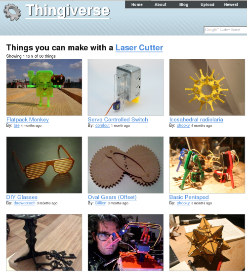
Thingiverse Tools System Released
I've been working on a new feature called Tools for Thingiverse lately which will make it much easier to find things to build and just make it a bit more tidy in general. For example, here is a page that lists things you can build with a RepRap machine.
If you want to know more, check out the Thingiverse blog post, or the newly discovered Tools Galaxy.
If you want to know more, check out the Thingiverse blog post, or the newly discovered Tools Galaxy.
For now we see through a glass, darkly...
In which your narrator's short-range IR radar set begins to return images... do you want to hear more?
Sunday, March 01, 2009
Wedge Design Proof Of Concept
 Ed has been discussing a proposal for a wedge-shaped version of the RepRap, using fewer components and being more easily manufactured than the existing box frame. One of the things we wanted to know was how badly it needed cross-bracing. So, I sliced & diced some MDF to give us an idea of how things might be spaced out, and to experiment with the bracing so I can have the rigidity and still maintain the same build volume as a Darwin.
Well, just 4 struts definitely isn't a stable design. Things wave about quite a bit under moderate load - which bodes badly for movement at just the wrong vibration frequency. Further mucking around revealed that this could be much reduced by bracing and I'm still fiddling with that to see how little I can get away with.
 Here's a shot showing the underside. Two of the X sliders are RepRapped by the way, and two are made from galvanised corner brackets and Polymorph. I thought it might be a good idea to make as many parts as possible in a way that could be replicated by hand if necessary.
I'd like to have the option of moving the axes with either motors & belts or threaded rod in the next design. In some parts of the world, high-quality steppers are unobtainable and so it makes sense to leave the path open to using current stepper/belt systems, develop DC-servo systems, and if all else fails drive it with a slow, old-fashioned threaded rod.
I'm not expecting this particular model to actually move properly, but if it does it'll be a really cheap way of putting RepRaps together.
Vik :v)
![]()