Monday, October 30, 2006
More thoughts on the Mk II...
I've been thinking some more about the Mk II. It's a great machine, but it's a little difficult for somebody with limited skills and tools to make up a few of the parts that aren't polymer.
After the nozzle, the threaded polymer pump is the biggest bother. The bushings are inset from the ends of the studding which means that you have to have split bushings, which are also a pest to make.

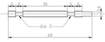
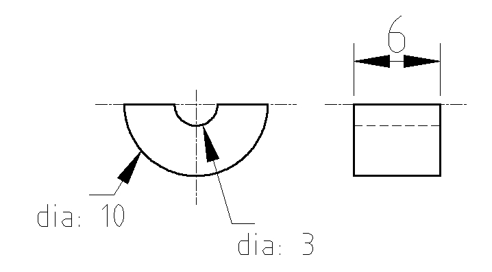
What would happen if you placed a bushing that seated at the lower end of the studding, which you'd turn down and another that slipped over the upper end as a sleeve. If you did that you could prepare the studding polymer pump in an ordinary electric drill with a metal file. You'd only have one threaded length instead of three, which would make seating bushings a lot easier.
As well, you could make the bushings out of square bar stock, probably brass. That you could secure in an ordinary vise with ease and drill with a hand-held electric drill or drill press if you had it and then saw the bushings off the bar after you'd drilled them.
It would also be nice if we shifted the drive motor over to a GM3 which has a short stub shaft coming out of the top of the gear box. That would let us install an AS5035 chip on top of the drive shaft and monitor filament feed rates and detect jams in real-time.
That takes me back to Vik's original drawing.
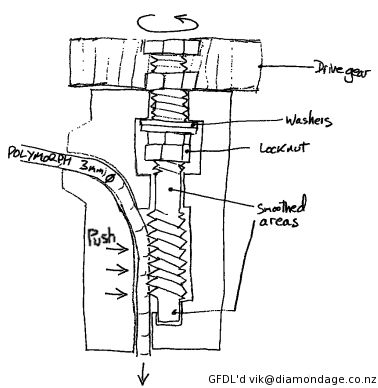 Note how Vik feeds the filament in from the side. I've wondered what is to stop us from making the pumped filament exit the pump along a radius, too. That would let us avoid the bottom bushing with the emerging filament. It would also let us put the polymer pump at a 90 degree angle or some other angle to the line of the extruder barrel. That would let us reduce the height of the overall assembly of the Mk II and make our overall machine a bit more compact and maybe use less material in the structure of the reprap.
Comments? Ideas? Rotten tomatoes? :-D

After the nozzle, the threaded polymer pump is the biggest bother. The bushings are inset from the ends of the studding which means that you have to have split bushings, which are also a pest to make.
What would happen if you placed a bushing that seated at the lower end of the studding, which you'd turn down and another that slipped over the upper end as a sleeve. If you did that you could prepare the studding polymer pump in an ordinary electric drill with a metal file. You'd only have one threaded length instead of three, which would make seating bushings a lot easier.
As well, you could make the bushings out of square bar stock, probably brass. That you could secure in an ordinary vise with ease and drill with a hand-held electric drill or drill press if you had it and then saw the bushings off the bar after you'd drilled them.
It would also be nice if we shifted the drive motor over to a GM3 which has a short stub shaft coming out of the top of the gear box. That would let us install an AS5035 chip on top of the drive shaft and monitor filament feed rates and detect jams in real-time.
That takes me back to Vik's original drawing.
 Note how Vik feeds the filament in from the side. I've wondered what is to stop us from making the pumped filament exit the pump along a radius, too. That would let us avoid the bottom bushing with the emerging filament. It would also let us put the polymer pump at a 90 degree angle or some other angle to the line of the extruder barrel. That would let us reduce the height of the overall assembly of the Mk II and make our overall machine a bit more compact and maybe use less material in the structure of the reprap.
Comments? Ideas? Rotten tomatoes? :-D
Friday, October 27, 2006
More on filament and threaded rods...
I took off a few days this week and drove down the coast to visit a few potential outfits that could potentially make parts and supplies for reprap.
Noll, Inc. down in San Luis Obispo offers a good range of Acme threaded rods and associated parts like thrust collars and bushings in a size range that would suit our reprap developments. The advantage of using acme rods are that they are accurate in the micron range, unlike the studding that we have been using.
The Acme thread rods are done in stainless steel and run in the range of $10-15/foot in the diameters and thread pitch ranges that we could use. They also offer thrust collars in anti-backlash designs for about $30. This stuff isn't cheap. Overall, however, it might be more cost-effective that studding in that we are having to do all sorts of things to force studding to do what we want that we could avoid having to do if we just went straight to Acme threaded rod.
Here are some details that I didn't know about before, though.
I feel that it will be a good idea to develop relationships with several suppliers of filament rather than dealing with one exclusively so that we will have some flexibility on delivery schedules and quantities as the demand for filament picks up in the next year or so.
Noll, Inc. down in San Luis Obispo offers a good range of Acme threaded rods and associated parts like thrust collars and bushings in a size range that would suit our reprap developments. The advantage of using acme rods are that they are accurate in the micron range, unlike the studding that we have been using.
The Acme thread rods are done in stainless steel and run in the range of $10-15/foot in the diameters and thread pitch ranges that we could use. They also offer thrust collars in anti-backlash designs for about $30. This stuff isn't cheap. Overall, however, it might be more cost-effective that studding in that we are having to do all sorts of things to force studding to do what we want that we could avoid having to do if we just went straight to Acme threaded rod.
Here are some details that I didn't know about before, though.
- the stuff comes in standard 6 foot lengths
- you can either pay them to mill the ends to fit bushings and motor couplings or do it yourself, which means that you will either have to have a precision lathe if you are going to make use of the accuracy of their acme threads or you will have to print your own polymer fittings to use on unmilled ends of this stuff
I feel that it will be a good idea to develop relationships with several suppliers of filament rather than dealing with one exclusively so that we will have some flexibility on delivery schedules and quantities as the demand for filament picks up in the next year or so.
Monday, October 23, 2006
objects.reprap.org
Just to let everyone know:
I've set up a MediaWiki at http://209.59.209.105/mediawiki/index.php/Main_Page. We'll be using this for our object file library site, objects.reprap.org . Currently "objects.reprap.org" doesn't point at the server, 209.59.209.105, but I have every expectation we'll sort that out shortly.
You are welcome to log onto it, upload files onto it, try to break it, etc. I'm going to be working on it quite a bit, but it should be fairly stable. Features, bug fixes, etc, will be in no small part community-driven, so please email me if it doesn't do what you want. Also email me at (penguin at supermeta dot I-hate-spam-too-so-delete-this-bit dot com) if you want administrator access or an ssh account on the server.
Edit: If you want to help work on the site, let me know - the more the merrier!
The 'Fab @ Home' project
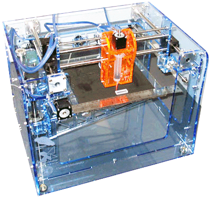
Evan Malone and Hod Lipson at Cornell have done some nice work;
They've got a syringe-based 3D printer, with full plans, up at:
http://128.253.249.235/wiki/index.php?title=Main_Page
It doesn't make copies of itself or work with thermoplastic but it's quite
impressive. The printer is made from laser cut acrylic sheet. "Approx.
$1500 RP system", according to a person who saw a talk by them.
It might be worth talking to these fellows and seeing if they would like to work together with us. I'm curious what license they're going to release his work under, what precision they're working at, and so on. They know about our project - they mention RepRap in their overview.
I think it would be extremely worthwhile to merge some of our work with
theirs, if we can sort out architectures, GPL, and so on. What do you guys think? At the very least we could use their system as a RepStrap, similar to Vik's flat-pack-RepStrap idea.
Polyethylene glycol as a potential water-soluble support mechanism.
I just stumbled across Polyethylene glycol (PEG)
http://en.wikipedia.org/wiki/Polyethylene_glycol
and have been thinking about picking some up and trying to use it as a potential water-soluble support mechanism. PEG is a flexible, non-toxic water-soluble wax-like polymer, used in cosmetics, toothpaste, and Dr. Pepper, along with who-knows-what else.
Jesse Brennan pointed out that Lee Valley sells PEG 1000 and PEG 1450 for CAD$6/lb (USD$11.25/kg). PEG 1000 melts at 37C, PEG 1450 melts at 43C. (PEG x means PEG with a molecular weight of x). Lee Valley is an expensive but high-quality Canadian woodworking tool store. They sell the PEG as a "green wood stabilizer".
via a random MSDS, http://www.jtbaker.com/msds/englishhtml/p5029.htm
"Melting Point:
Melting point increases as molecular weight increases: PEG 400 = 4-8C (39-46F) PEG 600 = 20-25C (68-77F) PEG1500 = 44-48C (111-118F) PEG 4000 = 54-58C (129-136F) PEG 6000 = 56-63C (133-145F) "
I do not know if we will be able to shape this stuff into filaments, but aside from that, it might work well for us.
Tuesday, October 17, 2006
Rethinking the Mk II heater nozzle...
We know the Mk II works. It has been the major breakthrough that makes the rest of RepRap possible.
I'm currently making a serious effort to get a Mk II going. As usual I can't ever seem to leave well-enough alone, though. :-(
The heater nozzle assembly of the Mk II has always been the most fraught for me.
It has always struck me that for something that is supposed to be made in the wilds of Africa that part of the assembly seems remarkably sophisticated.
First off, you really need a lathe to make the brass heater nozzle. You might as well need a lathe to run a straight hole through several inches of PTFE rod.
 I've tried it a number of times both freehand and with a drill press with a cross slide vise. I finally had to drill a hole in a block of wood and slide the PTFE rod into that to even hope to get the job done properly. It's a real pain for a retard like me.
One thing that bothers me about that heater nozzle, aside from the fact that it's a bugger to make, is that it has a lot of material in it and as a result has a considerable time constant.
As designed by Adrian the thing has just over a cubic centimetre of brass in it.
Depending on the brass you use that's about 8.5 grammes.
In order to make it easier to unjam Vik has added a nut onto the end of it. That's handy but it adds more mass onto the nozzle and thus increases the time constant.
That seems to have become the standard heater nozzle design for right now. Here's a neat one done by TylerM.
Okay, so we have a way to do it. Problem with the one we have is that it seems to be a fairly finicky thing to make. You also need to screw it into that PTFE rod.
In practice Vik has discovered that he has to periodically park the extruder and also needs to keep a fan on it to make it work right.
I got to wondering if you couldn't somehow make one somewhat more easily. This evening I took a shot at doing a mockup of one that I could make in the wilds of Africa if I needed to.
I've been eyeing some 5/32" hard copper tube in the hardware for some weeks. A foot of it costs US$0.75. This afternoon I took my micrometer and a piece of the CAPA filament that Jim sent along to see if would fit.
Sure enough the CAPA filament fit wonderfully into the hard copper tube. The inside diameter is spot on at 3.05 mm. Unlike the ones we are making now, however, the wall thickness of this premade tube is only 0.47 mm instead of 1.5 mm in the original lathe-made heater nozzle.
The whole diameter of this 3 mm ID tube is only about 3.94 mm. An equivalent length of this stuff weighs only 2.54 grammes as opposed to just at 8.5 for the original design. That's about 70% lighter than the original design and the good Lord only knows how much lighter than the one that has a nut on the end.
I had some 25x25 mm PTFE block lying around from some earlier work with the auger bit extruder I designed months ago. I had bought it to give strength to the 1/2 inch rod that I used to separate the auger pump from the heater barrel. I'd discovered that when you pressurize PTFE when it's hot it bulges.
It struck me that that 25x25 mm cross section bar would be a heck of a lot easier to seat in a cross-slide vice on a drill press. As well, you could bolt it to the bottom of the Mk II's polymer pump instead of using that friction grip that Vik had noted tended to slip when you overpressured.
So, here's what I did. I didn't want to screw or friction fit the copper tube into the PTFE. I made a flaring mandrel out of a piece of scrap steel by drilling a 5/32 inch hole in it then countersinking a 1/4 inch hole into it to make a flaring die.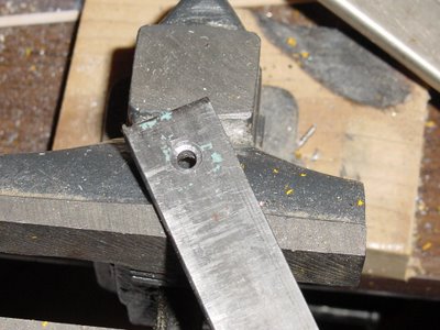
Once I'd made that I cut a 55 mm piece of the tube.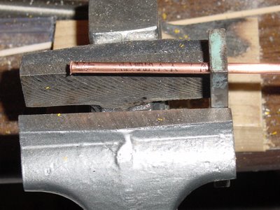
The die serves as a good way of gripping the tubing while you use a hacksaw on it.
I then used the 5/32 inch drill bit run backwards to create a lip on the end of the tube.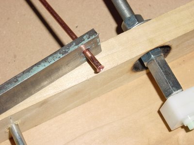
After that I cut a square washer for the flared nozzle out of 0.7 mm copper sheet (the kind you engrave stuff on for trophies or discreet business signs by office doors.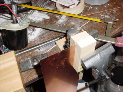 It's good to secure this stuff between two scraps of wood when you saw it so that you don't warp it.
After that you seat the heater nozzle in the washer. I set out to buy a 0.5 mm drill bit but was only able to get a 1 mm drill bit, so I used it for this exercise. What i did instead of drilling with it was to use it to form the extrusion orifice when I crushed the end of the copper tube down on the drill bit.
Afterwards I realised that any steel wire of the proper diameter would have done the job just as well.
I touched up the nozzle with my Dremel tool.
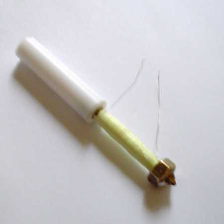
I was then ready to saw off a piece of 25x25 PTFE bar and drill it to seat the heater nozzle.
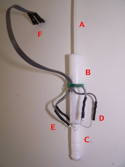
What you wind up with is quite a robust heater nozzle assembly.
Here you see it with a piece of CAPA filament fed into it.
You then make your PTFE filament guide and thermal barrier out of a 50 mm piece of 25x25 mm bar stock and drill the 3 mm hole through it's centre. You can then secure the heater nozzle assembly to the thermal barrier by drilling a hole at each corner of the bar stock and securing it to the polymer pump assembly with something like M3 studding and lock washers and nuts.
What I'm hoping I have here is a heater barrel and nozzle that is easier to make that can handle higher temperatures and heater barrel pressures so that we can try some other polymers like PLA, HDPE and polypropylene. With a little luck the smaller thermal time constant for the heater head will make it more quickly responsive to energy input changes and reduce the need for setting it aside occasionally.
I'm currently making a serious effort to get a Mk II going. As usual I can't ever seem to leave well-enough alone, though. :-(
The heater nozzle assembly of the Mk II has always been the most fraught for me.
It has always struck me that for something that is supposed to be made in the wilds of Africa that part of the assembly seems remarkably sophisticated.
First off, you really need a lathe to make the brass heater nozzle.
 You might as well need a lathe to run a straight hole through several inches of PTFE rod.
 I've tried it a number of times both freehand and with a drill press with a cross slide vise. I finally had to drill a hole in a block of wood and slide the PTFE rod into that to even hope to get the job done properly. It's a real pain for a retard like me.
One thing that bothers me about that heater nozzle, aside from the fact that it's a bugger to make, is that it has a lot of material in it and as a result has a considerable time constant.
As designed by Adrian the thing has just over a cubic centimetre of brass in it.
Depending on the brass you use that's about 8.5 grammes.
In order to make it easier to unjam Vik has added a nut onto the end of it.
 That's handy but it adds more mass onto the nozzle and thus increases the time constant.
That seems to have become the standard heater nozzle design for right now. Here's a neat one done by TylerM.
Okay, so we have a way to do it. Problem with the one we have is that it seems to be a fairly finicky thing to make. You also need to screw it into that PTFE rod.
In practice Vik has discovered that he has to periodically park the extruder and also needs to keep a fan on it to make it work right.
I got to wondering if you couldn't somehow make one somewhat more easily. This evening I took a shot at doing a mockup of one that I could make in the wilds of Africa if I needed to.
I've been eyeing some 5/32" hard copper tube in the hardware for some weeks. A foot of it costs US$0.75. This afternoon I took my micrometer and a piece of the CAPA filament that Jim sent along to see if would fit.
Sure enough the CAPA filament fit wonderfully into the hard copper tube. The inside diameter is spot on at 3.05 mm. Unlike the ones we are making now, however, the wall thickness of this premade tube is only 0.47 mm instead of 1.5 mm in the original lathe-made heater nozzle.
The whole diameter of this 3 mm ID tube is only about 3.94 mm. An equivalent length of this stuff weighs only 2.54 grammes as opposed to just at 8.5 for the original design. That's about 70% lighter than the original design and the good Lord only knows how much lighter than the one that has a nut on the end.
I had some 25x25 mm PTFE block lying around from some earlier work with the auger bit extruder I designed months ago. I had bought it to give strength to the 1/2 inch rod that I used to separate the auger pump from the heater barrel. I'd discovered that when you pressurize PTFE when it's hot it bulges.
It struck me that that 25x25 mm cross section bar would be a heck of a lot easier to seat in a cross-slide vice on a drill press. As well, you could bolt it to the bottom of the Mk II's polymer pump instead of using that friction grip that Vik had noted tended to slip when you overpressured.
So, here's what I did. I didn't want to screw or friction fit the copper tube into the PTFE. I made a flaring mandrel out of a piece of scrap steel by drilling a 5/32 inch hole in it then countersinking a 1/4 inch hole into it to make a flaring die.

Once I'd made that I cut a 55 mm piece of the tube.

The die serves as a good way of gripping the tubing while you use a hacksaw on it.
I then used the 5/32 inch drill bit run backwards to create a lip on the end of the tube.

After that I cut a square washer for the flared nozzle out of 0.7 mm copper sheet (the kind you engrave stuff on for trophies or discreet business signs by office doors.
 It's good to secure this stuff between two scraps of wood when you saw it so that you don't warp it.
After that you seat the heater nozzle in the washer.
 I set out to buy a 0.5 mm drill bit but was only able to get a 1 mm drill bit, so I used it for this exercise. What i did instead of drilling with it was to use it to form the extrusion orifice when I crushed the end of the copper tube down on the drill bit.
Afterwards I realised that any steel wire of the proper diameter would have done the job just as well.
I touched up the nozzle with my Dremel tool.
I was then ready to saw off a piece of 25x25 PTFE bar and drill it to seat the heater nozzle.
What you wind up with is quite a robust heater nozzle assembly.

Here you see it with a piece of CAPA filament fed into it.

You then make your PTFE filament guide and thermal barrier out of a 50 mm piece of 25x25 mm bar stock and drill the 3 mm hole through it's centre. You can then secure the heater nozzle assembly to the thermal barrier by drilling a hole at each corner of the bar stock and securing it to the polymer pump assembly with something like M3 studding and lock washers and nuts.
What I'm hoping I have here is a heater barrel and nozzle that is easier to make that can handle higher temperatures and heater barrel pressures so that we can try some other polymers like PLA, HDPE and polypropylene. With a little luck the smaller thermal time constant for the heater head will make it more quickly responsive to energy input changes and reduce the need for setting it aside occasionally.
Monday, October 16, 2006
CAPA filament arrives...
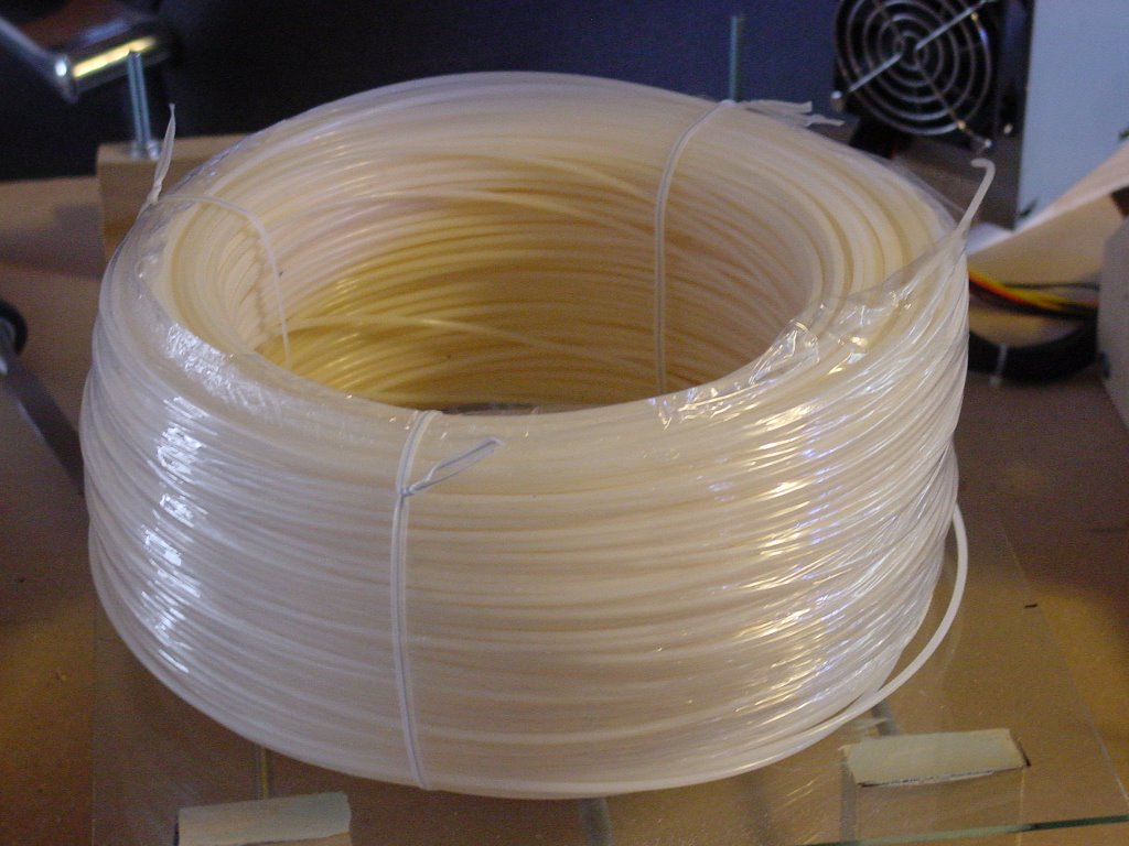
The CAPA filament that Image Plastics made up for us arrived a little while ago.
As you can see it looks beautiful.
I measured its diameter in about 5-6 places and on the downside it's running 2.8 mm +/- 0.009 which works out to 0.11 inches. A diameter of 3 mm works out to 0.11811 inches.
The consistency of the filament is what Jim said it would be but the filament itself is 0.2 mm too thin. I'm guessing that somebody' vernier is set in inches and somebody set the filament winder wrong. I'm going to talk to Jim about this in the morning and see if that's all the problem is.
Vik tells me that the Mk II will happily eat filament ranging from 2.7-3.0 mm so this batch isn't wasted. Perhaps we can put an initialisation datum of the effective filament diameter in to the Mk II controller programme so that we can keep track of mass flow very accurately.
Sunday, October 15, 2006
Bug fix on the Experimental Involute Profile Gear script...
Vik was testing the Experimental Involute Profile Gear script this weekend and discovered that I'd left an active print statement in the code. I've commented it out in the uploaded script that you can get here.
Tuesday, October 10, 2006
Upgraded AoI Involute Profile Gear script...
Okay campers, I got it done and tested for a first cut. My opinion of Java does not improve with acquaintance. I don't see how you guys can stand to work with that Sun "compiler". I won't say more than that.
Anyhow, you can get a copy of the new script which is called "Experimental Involute Profile Gear" to differentiate it from the older script that I wrote some months back. You can get a copy here.
I made a few screen grabs of some gear pairs that I did with the new script. I did Vik's 79 toothed gear and mated it with an 11 toothed gear.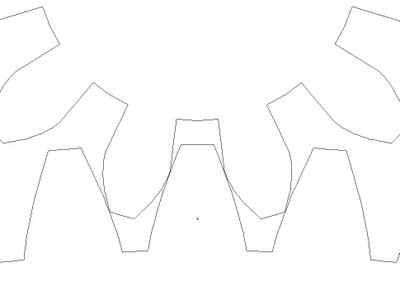
The pressure angle used was 20 degrees.
After I'd done that I decided to really test the robustness of the routine by pressing the envelope. Here is a 99:1200 ratio gear pair also done with a 20 degree pressure angle.
I then checked to see that I could triangle mesh the profiles and extrude them. There doesn't appear to be any problem. Here's Vik's example again.
 Don't run this script with pressure angles larger than 25 degrees, please. I don't want to have to debug any more #$#@##$ Java again for a few weeks, thank you so very much. :-/
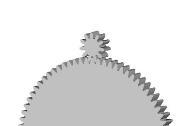
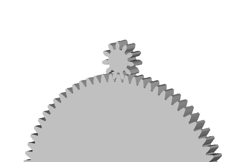
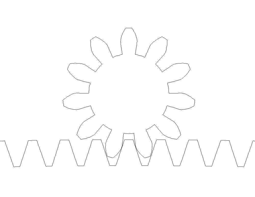
Finally, here is an example of what I am talking about when I speak of using the same code for both rack and pinion design.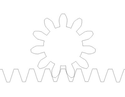
Here you have a 11:1201 ratio gear pair. The 1201 toothed gear for quite reasonable distances is very much a rack for the 11 toothed pinion gear.
Anyhow, you can get a copy of the new script which is called "Experimental Involute Profile Gear" to differentiate it from the older script that I wrote some months back. You can get a copy here.
I made a few screen grabs of some gear pairs that I did with the new script. I did Vik's 79 toothed gear and mated it with an 11 toothed gear.

The pressure angle used was 20 degrees.
After I'd done that I decided to really test the robustness of the routine by pressing the envelope.
 Here is a 99:1200 ratio gear pair also done with a 20 degree pressure angle.
I then checked to see that I could triangle mesh the profiles and extrude them. There doesn't appear to be any problem. Here's Vik's example again.
 Don't run this script with pressure angles larger than 25 degrees, please. I don't want to have to debug any more #$#@##$ Java again for a few weeks, thank you so very much. :-/
Finally, here is an example of what I am talking about when I speak of using the same code for both rack and pinion design.
Here you have a 11:1201 ratio gear pair. The 1201 toothed gear for quite reasonable distances is very much a rack for the 11 toothed pinion gear.
Upgrading the AoI Involute Profile Gear Script...
It appears that a decent fix for the too many teeth pathology in the involute profile gear script is to simply chop off anything that the script tries to draw that falls below the inner radius. I've written and tested the code for that in VB.NET 2005 and the results look good.
I've tested it up to a gear with a radius of 1000 and 360,000 teeth. The teeth are triangular with the top of the triangle chopped off at that resolution, but hey, what did you expect? :-) It very much looks like I can generate a rack with this coding by using a very large radius and then doing only a partial, very shallow arc.
Right now I'm translating the code into Java so that AoI will eat it. That task is about as much fun as getting an onlay at the dentist's on a rainy afternoon.
I'll publish some screen grabs from AoI and pass around the script as soon as I get it running.
The code appears to be robust as long as you don't specify a pressure angle higher than about 25 degrees. That shouldn't be a problem.
Sunday, October 08, 2006
Involute profile gear tooth script pathology.
Now I can see what's happening. After reviewing the Luleå Tekniska Universitet example and going back and working with the script that we are currently using I'm pretty sure I know what is causing the script pathology.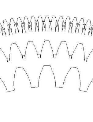
If you look at this screen grab pulled from AoI you can see pretty clearly what's happening.
I've run the script for three gears; 40 teeth with a radius of 1.5, 75 teeth with a radius of 1.75 and 200 teeth with a radius of 2.
The 40 toothed example works right. You can see the line that describes the bottom of the tooth which connects to a radial line that runs up to where the involute profile curve begins. That line at the bottom of the tooth should be an arc, but never mind that for now. In the script code it is called RI. The radius where the involute profile begins is called RB.
If you will look at the 75 toothed example (the next one up) you see that what has happened is that the value for RB has become less than the value for RI.
That is what is causing the pathology.
If you then look at the 200 toothed gear at the top you can see that RB has been driven down to a point where the two involute profile curves are actually overlapping. The gap between the teeth is actually higher than the crossing point.
It appears that what I need to do is make sure that the involute profile curve can never extend below the boundary defined by the radius RI.
I'll try to fix that now.
Here's the fascinating part, though. I was looking at that 200 toothed gear at a high magnification and realised that it is approximating a rack!
A rack can be considered to be nothing more than another involute profile gear with a extremely large radius and number of teeth. That may well let me use the same script for both rack and pinion!
Woo Hoo! :-D

If you look at this screen grab pulled from AoI you can see pretty clearly what's happening.
I've run the script for three gears; 40 teeth with a radius of 1.5, 75 teeth with a radius of 1.75 and 200 teeth with a radius of 2.
The 40 toothed example works right. You can see the line that describes the bottom of the tooth which connects to a radial line that runs up to where the involute profile curve begins. That line at the bottom of the tooth should be an arc, but never mind that for now. In the script code it is called RI. The radius where the involute profile begins is called RB.
If you will look at the 75 toothed example (the next one up) you see that what has happened is that the value for RB has become less than the value for RI.
That is what is causing the pathology.
If you then look at the 200 toothed gear at the top you can see that RB has been driven down to a point where the two involute profile curves are actually overlapping. The gap between the teeth is actually higher than the crossing point.
It appears that what I need to do is make sure that the involute profile curve can never extend below the boundary defined by the radius RI.
I'll try to fix that now.
Here's the fascinating part, though. I was looking at that 200 toothed gear at a high magnification and realised that it is approximating a rack!

A rack can be considered to be nothing more than another involute profile gear with a extremely large radius and number of teeth. That may well let me use the same script for both rack and pinion!
Woo Hoo! :-D
More work on the involute profile gear script for AoI
This morning I was cleaning loose papers from under my PC table and discovered the printout of the original example code for generating the gear profiles from Luleå Tekniska Universitet. I had neglected to download a copy and simply printed out the PDF file. After I'd got the AoI script going the printout slid off the back of my PC table into the drift of similar papers that collects back there. I'd been unable to get recover the link to the document via google since then.
Anyway, once I had the printout I googled a sentence out of the document and got the document back. You can link to it here. I also grabbed a copy and dumped it into the documents folder of the RepRap folder on my own server so that we will still have a copy of it if, for some reason, Luleå takes that document down. You can link to that copy here.
Some of you might want to keep copies of this rather vital document so that the RepRap project still has it regardless of server and disk crashes.
BTW, the example code begins on page 444 of that Swedish document (page 20 in the PDF).
There is also a copy of Cory Doctorow's short story "Printcrime" in there. :-D
I am going to spend some time going over the involute profile gear script for AoI again this morning to see if we actually have a coding problem in the original Swedish programme or perhaps a misinterpretation of what they meant when I translated their logic over to VB.NET and thence to Java.
![]()