Tuesday, May 31, 2005
Finned extruder
As you can see in the photo below, I've looked at the possibility of using fins to keep the entrance end of the Polymorph extruder cool. I got the idea off a gas-powered soldering iron pictured on the right. The 12mm aluminium cylinder has fins carved half-way through. These were made by rotating the cylinder in a power drill and hacking away with a large hacksaw.

Heating the cylinder up to 180C with a soldering iron resulted in a 10C temperature drop across the fins. Further experiments will use more fins, wider gaps between them, and some form of variable power supply for the soldering iron. We'll need at least 60C of temperature drop across the fins in order to reach the extrusion temperature of 120C Adrian was using without prematurely melting the incoming Polymorph.
The new AS5040 magnetic sensor samples from Austriamicrosystems arrived today, and let me say that these people really know how to provide sample kits. They even provided a small, battery-powered demonstration board with the samples and a little magnet. Vielen dank, guys!
Vik :v)
Sunday, May 29, 2005
Postscript to polymorph extrusion
On a whim, I put an M4 die in my lathe chuck, set the lathe on its slowest speed, and fed in one of the 4mm polymorph rods I made for the extrusion experiments described below. I held the free end with a pair of pliers to stop it from rotating. The result was an M4 thread right down the rod:

I put a nut on it and used that to push a tube with an i.d. of 4mm against a set of scales. It held to over 100N (then I had to stop pushing...). This gives an interesting way to feed the material into an extruder: thread it, then wind a nut against a stop to force it into a heating chamber. Here's a crude sketch:


I put a nut on it and used that to push a tube with an i.d. of 4mm against a set of scales. It held to over 100N (then I had to stop pushing...). This gives an interesting way to feed the material into an extruder: thread it, then wind a nut against a stop to force it into a heating chamber. Here's a crude sketch:

On these matters, Steve DeGroof e-mails to say: "Not sure if this would work but have you considered using airbrush nozzles? They typically come in 0.6mm, 0.4mm and 0.2mm sizes. You usually have to order the nozzle, needle and cap as a set but they should still be fairly inexpensive." This seems a neat idea to save people having to machine nozzles.
Polymorph moulding
Using some Wood's metal, I made a mould of the end gear on an HP printer motor; it's a toothed gear that engages directly with the drive belt. It took some effort to separate the mould from the original gear, and despite warming everything up with a hairdryer first, a large air bubble formed inside. You can see where some Polymorph got trapped in it in this photo:

Undaunted, I drilled out the hole left by the shaft to suit Meccano shafts, and tapped a shaft gently home with a large mallet. If I had been thinking, I would have sprayed a little oil in at this point, and anchored the shaft in the vertical position.
Hot Polymorph was pressed firmly into the hole around the shaft, and a 2-hole Meccano collar pushed in on top. One of the holes embedded itself nicely in the Ploymorph, and the other stuck out allowing me to attach the collar to the shaft with a grub screw. For a permanent fit, Adrian suggests puting a flat on the shaft.
Getting it out was a mission, as the Polymorph had invaded the cavity well. Consequently, the gear was slightly distorted after extraction, and mildly eccentric. This was fixed up with a hot knife, and re-centred after warming the shaft with a hair dryer.
The gear is now in use in the Meccano trolley prototype and will do until I can get a replacement FDM'd up. As it is on a collar with attachment grubscrew, I have been able to change my mind over the length of the shaft it is mounted on a couple of times. Emulating this in an FDM'd model will be fun!
Vik :v)
Turntable Scanner
I thought I'd better document an idea that I saw in O'Reily's "Make" blog while looking at postings about RepRap - I'm unable to find the original link. The concept was to use a rotating turntable and a moving laser pointer in conjunction with a video camera and some clever software to scan in and digitise an object.
Well, the Meccano turntable would both rotate and lower the object simultaneously so a static laser pointer could be used. As the method was already proved, it would appear that RepRap + laser pointer + video camera = 3D scanner.
Unfortunately I'm a bit busy making the fabricating side of things, but if anyone wishes to make a turntable-based scanner do let me know how you get on!
Vik :v)
Saturday, May 28, 2005
Extruding polymorph
Vik has succeeded in rolling accurate polymorph rods and putting them through a glue gun:

I decided to try some more extrusion experiments with it.
(Lest we all lose our sense of wonder, not - of course - at the RepRap project, but at the prodigious communication technology of the age, I'd just like to take a sentence to say how extraordinary it is to conduct experiments collaboratively with a person whom one has never met, never even talked to, and who is positioned antipodally as far away as it is possible to get and still be on the same planet; the results flash to and fro through light-fibres and a 12-hour time difference and appear instantly on a blog that is stored in a Google/blogger.com Linux box in San Francisco or Mountain View, CA; this again is about as far as it is possible to get from both of us... as Vik himself said, 'Fun this, innit?')
First I made a nozzle from an ordinary M4 screw:

I cut off all but a few mm of the thread, drilled out that thread from the back with a 1.5 mm drill almost but not quite to the top face of the head, then finished the hole with an 0.4mm drill (which is quite tricky to hold in a chuck, I can tell you...). Then I turned the head down to a shallow cone in a lathe.
Next I made an aluminium block with a 4mm hole almost all the way through, and tapped the last few mm at M4 for the nozzle.

I cut a slot in the block to fit the heater out of a glue gun. I greased a 4mm plastic rod with vaseline, put a tight-fit O-ring on it, and pushed it down the 4mm hole. In an oven set at 100 degrees C I cast a block of isocyanate/polyol thermoset round this to give a lead-in for the polymorph rod where it would be kept at a low enough temperature to maintain it as a solid. Here came a piece of serendipity: isocyanate+polyol normally needs to be cast in a vacuum to outgas it in order to get a decent result. But here the bubbles it generates as it sets became a positive advantage - they made the block weaker, but they lowered its thermal conductivity, keeping the right-end cool, even when the aluminium block was at full temperature. The isocyanate held the O-ring well, giving a good seal.
Not shown on the diagram above are 4 M3 screws. I drilled and tapped the aluminium block M3 where it would join to the thermoset and put four screws in with their heads protruding about 4 mm. These were to give a strong key for the thermoset to hold it onto the block.
Before I did all this I boiled up a scrap lump of isocyanate in cooking oil - it was stable and happy up to at least 180 degrees C. Here is the finished extrusion head together with a rolled length of polymorph. The hole bottom right is for a thermometer.

(Incidentally, glue gun heaters are really simple - they consist of a ceramic resistor sandwiched between two aluminium plates with a small spring plate to make the whole thing push-fit. The result is wrapped in a high-temperature polymer sheet for electrical insulation. The mains is connected across the aluminium plates. The resistor is about 800 ohms at 20 degrees, but this rises with temperature, giving an amount of negative feedback.)
As Vik found, the 4mm polymorph rods are very easy to make. You just put a lump of the stuff in boiling water to soften it, take it out, and roll it between two flat rigid plates using a 4mm diameter rod to get the thickness. You might imagine that you would get the best results with two such rods, one either side of the rolling polymorph, but it actually works better with just one. This gives a slightly undesized rod, as the plates are at a slight angle to each other. But the physics of the situation makes the polymorph roll immediately adjacent to the rod, so the reduction in diameter is very small. And, if you stop rolling before the polymorph fully sets it springs back a small amount, compensating for its reduced diameter.
I used polymorph granules from Maplin, but Vik also found a company (see below) making a similar material already in rod form: WFR / Aquaplast.
Finally I put the whole thing together, plugged in the heater, and pushed the polymorph rod through by hand. I would guess that I was using a force of about 70N.

The material extrudes well at around 120 to 130 degrees C. Note the change in colour as it sets. The final diameter was 0.5mm, indicating a small amount of die-swell, as would be expected.
I decided to try some more extrusion experiments with it.
(Lest we all lose our sense of wonder, not - of course - at the RepRap project, but at the prodigious communication technology of the age, I'd just like to take a sentence to say how extraordinary it is to conduct experiments collaboratively with a person whom one has never met, never even talked to, and who is positioned antipodally as far away as it is possible to get and still be on the same planet; the results flash to and fro through light-fibres and a 12-hour time difference and appear instantly on a blog that is stored in a Google/blogger.com Linux box in San Francisco or Mountain View, CA; this again is about as far as it is possible to get from both of us... as Vik himself said, 'Fun this, innit?')
First I made a nozzle from an ordinary M4 screw:
Next I made an aluminium block with a 4mm hole almost all the way through, and tapped the last few mm at M4 for the nozzle.
I cut a slot in the block to fit the heater out of a glue gun. I greased a 4mm plastic rod with vaseline, put a tight-fit O-ring on it, and pushed it down the 4mm hole. In an oven set at 100 degrees C I cast a block of isocyanate/polyol thermoset round this to give a lead-in for the polymorph rod where it would be kept at a low enough temperature to maintain it as a solid. Here came a piece of serendipity: isocyanate+polyol normally needs to be cast in a vacuum to outgas it in order to get a decent result. But here the bubbles it generates as it sets became a positive advantage - they made the block weaker, but they lowered its thermal conductivity, keeping the right-end cool, even when the aluminium block was at full temperature. The isocyanate held the O-ring well, giving a good seal.
Not shown on the diagram above are 4 M3 screws. I drilled and tapped the aluminium block M3 where it would join to the thermoset and put four screws in with their heads protruding about 4 mm. These were to give a strong key for the thermoset to hold it onto the block.
Before I did all this I boiled up a scrap lump of isocyanate in cooking oil - it was stable and happy up to at least 180 degrees C. Here is the finished extrusion head together with a rolled length of polymorph. The hole bottom right is for a thermometer.
(Incidentally, glue gun heaters are really simple - they consist of a ceramic resistor sandwiched between two aluminium plates with a small spring plate to make the whole thing push-fit. The result is wrapped in a high-temperature polymer sheet for electrical insulation. The mains is connected across the aluminium plates. The resistor is about 800 ohms at 20 degrees, but this rises with temperature, giving an amount of negative feedback.)
As Vik found, the 4mm polymorph rods are very easy to make. You just put a lump of the stuff in boiling water to soften it, take it out, and roll it between two flat rigid plates using a 4mm diameter rod to get the thickness. You might imagine that you would get the best results with two such rods, one either side of the rolling polymorph, but it actually works better with just one. This gives a slightly undesized rod, as the plates are at a slight angle to each other. But the physics of the situation makes the polymorph roll immediately adjacent to the rod, so the reduction in diameter is very small. And, if you stop rolling before the polymorph fully sets it springs back a small amount, compensating for its reduced diameter.
I used polymorph granules from Maplin, but Vik also found a company (see below) making a similar material already in rod form: WFR / Aquaplast.
Finally I put the whole thing together, plugged in the heater, and pushed the polymorph rod through by hand. I would guess that I was using a force of about 70N.
The material extrudes well at around 120 to 130 degrees C. Note the change in colour as it sets. The final diameter was 0.5mm, indicating a small amount of die-swell, as would be expected.
Thursday, May 26, 2005
Polymorph and similar materials
I've been dregding for information on Polymorph. Louis-Philippe Breton suggests Polymorph is a polymer known as Polycaprolactone(PCL). Unfortunately, it seems this may be biodegradable. Bad in engineering terms, and also bad for the environment. [Why? It limits the recycling and puts the carbon that was locked safely away back in circulation in the atmosphere.]
Similar materials to Polymorph appear to be:
Protoplast, sheet and pellets, various colours:
http://www.wfr-aquaplast.com/tmppcc_default.htm
http://www.wfr-aquaplast.com/pages/protosheets.html
Shapelock:
http://shapelock.com/
Friendly Plastic by Amoco, various colours and sticks:
http://www.sunshinecrafts.com/body_friendly_plastic.html
Hexcelite / X-lite / Vara-form:
http://www.runlite.com/varaform/index.html
Polymorph samples have now arrived in New Zealand and have already found a use as gripping pads for the drive belt. This will be fitted directly to the Meccano trolley for the test phase. An experiment was performed to see if simple centrifuging of a syringe of hot polymorph can drive out the air bubbles. It can, but unfortunately, the resulting polyblob cannot be extruded from the syringe, even when boiled. As the syringe is also somewhat pliable at this point, it can be squeezed, separating the hot polymorph from the side of the syringe barrel and rescuing the syringe.
The FDM'd brackets arrived and are fine, except for a user malfunction that resulted in the holes being designed precisely 1mm too narrow. Expect an update to the AOI files in the near future.
Samples of magnetic rotation counters - which will be impervious to dust and other deposited crud - have been approved by Allegro, and dispatch is expected shortly. These are sensitive enough to detect individual teeth on a ferrous gearwheel rotating at 1,000+ RPM. They are designed for automotive applications, and so should ultimately be available from car spares suppliers.
Vik :v)
Saturday, May 21, 2005
Axis Debut
I've made an axis (like the kind you'd find in a printer) which can deposit molten bend alloy into casting channels in a pre-manufactured component. The key thing is that the axis was desinged in-line with the self-replicating idea: most structural parts are made using RP technology, and most other parts are from the accepted parts list. There are a few exceptions to this, like linear bearings and a tooth belt, but that's OK for the first prototype.
On Friday the axis dripped its first drip! We put a test plate (with lots of straight channels in it) under the needle, fired up the stepper motor to move the carriage and started pumping the injector. The first few attempts were just about getting the co-ordination right, so don't pay too much attention to the lower channels, but if you check out the top channel you can see a 2 cm length of deposited alloy. On solidification the deposition was continuous and robust. And this was only the fourth attempt. The parameters had been a stab in the dark but the final carriage speed was approximately 5 mm/sec and injector motor had been at 10 Volts.
eD
PS> The report is on its way to the download section

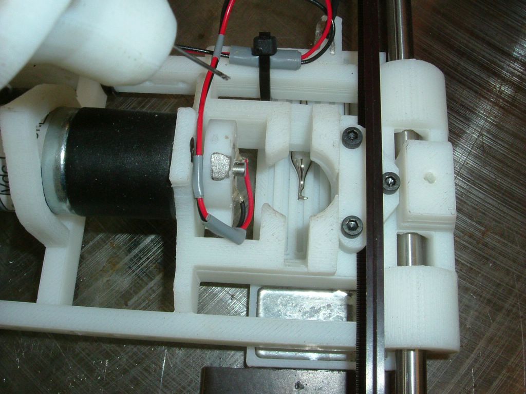
Injector lifted up immediately after doing a deposition run to show the testing plate which channels underneath the carriage

Test piece with bend alloy deposited (by the axis) into the channels. The first runs were about getting the co-ordination right. The final run (top channel) made a continuous deposition.
Friday, May 20, 2005
3-Axis Meccano Prototype
By sticking the auto-descending turntable on a linear carriage, I've turned the Meccano prototype into a 3-axis machine that only uses 2 motors for positional control. I've not fitted the carriage actuator yet, but here's the prototype:

Once a layer has been deposited, the stage will rotate through 360 degrees and thus lower by 0.25 mm automatically.
This simplifies the control hardware, though the software becomes more interesting.
More than one head can me implemented along the length of the carriage, so plastic/icing tests should be possible.
My PIC prototype board can be seen against the right edge of the photo.
Vik :v)
Wednesday, May 18, 2005
PIC Sofware Development Kits
For those using various varieties of PICs, this page is most useful for getting one up and running to build user-confidence. How to blink a light on umpteen different PICs:
http://www.voti.nl/blink/index_1.html
I have successfully used the ic-prog Windows software under the WINE Linux environment with a JDM-style "Silicon Chip 2003" PIC Programmer:
http://www.ic-prog.com
It was unhappy and believed the copy protect bit to be set until I turned the I/O Wait up to 17 in the hardware settings and picked "Windows API" to control the serial port. Now I can reliably program 16F628A's using hex files of my own creation that were compiled with sdcc.
[Sigh of relief]
Vik :v)
Sunday, May 15, 2005
Square eyes
Hello world (my first ever blog)
I'm the kid in the cellar trying to get a self replicating axis to work. My dissertation deadline on Friday prevents me seeing properly, so I'm not typing any more - here's a sneak preview of things to come instead...
I'm the kid in the cellar trying to get a self replicating axis to work. My dissertation deadline on Friday prevents me seeing properly, so I'm not typing any more - here's a sneak preview of things to come instead...
Saturday, May 14, 2005
The Icing on the Cake
Icing sugar turns out to be a wonderful material for doing extrusion experiments, because:
So I dug an old Cartesian robot out of a cupboard at the University (it was made in the 1980s...), upgraded its electronics so they were the size of a dictionary, not a suitcase, and put one of our syringe pump heads on it (the pump contains the first part out of AoI Vik mentions below). The pump has one of our heating jackets round it, but I didn't use that for these experiments - hence the unconnected angled hole at its front. Here it is (with the head enlarged top right):

I filled the pump with icing sugar and set it scribbling. It quickly became obvious that the secret is flow control (note panic button added as an afterthought to the syringe pump...). By adjusting the pump voltage, however, it was quite easy to get a good consistent track:

The good track is actually two, one laid on top of the other after the first dried. They stack well, and are about 1mm wide. This is too fat because I used too fat a hypodermic needle, but the process actually seems to work better the finer you go. However, like any good cook, you have to avoid lumps when you mix the icing sugar - sieve it first... To get the good track I had to anticipate the starts and ends with the panic button, making the motor run before the robot started its movement, and reversing it for a few seconds before the end to avoid blobbing. The problem is the elasticity of the syringe-pump components, which store pressure energy and cause the flow to continue after the pump motor stops.
So finally I made a crude valve on the end of the syringe by interpolating a 2cm length of silicone tube between the syringe and the needle. The result would no longer fit in the syringe pump nor on the robot, so I just pressurized the syringe permanently using a spring, and clamped the silicone tube in a pair of long-nosed pliers. This gave perfect control, and you can sign your name with the thing.
So. We may be able to replace the syringe pump with something much simpler:

On the left is a micropipette tip. This has a hole in the end with a diameter of 0.4mm, which is about the same extrusion diameter as commercial FDM machines. It is a throw-away item costing pence, and for RepRap may represent a better bet than syringe needles as its tapering form offers less flow resistance. In the middle is the cut-off end of the tip in a silicone tube, with a diagram showing a pressurized reservoir of deposition material and a simple clamp (A). The clamp is all that is needed to make a very effective valve. This could be opened and closed with a solenoid, or maybe a radio-control servo (right).
The rule in the picture is not really bent - that's the wide angle macro setting on my camera...
A simple string-weight-and-pully experiment (below) shows that the force needed to shut off flow in the tube is 13N, though this may be a bit higher if the upstream pressure is greater than the 300mm water head that you can see in the picture, and a bit lower if the tube were to be squashed using a sharp edge instead of the flat face of a pair of pliers.

For other materials (polymorph, Wood's metal) the pipette tip can withstand temperatures of about 100 degrees C (maybe higher, that's just as far as I got), and the silicone tube is happy up there too.
- You can work at room temperature,
- You can get any viscosity you like by changing the sugar/water ratio (mix in a little glycerin too),
- It is completely benign,
- It holds its shape perfectly when you lay it down,
- Fine strands set very quickly because they have a high area:volume ratio for water evaporation (especially if you hit them with a few seconds from a hair dryer...), and
- It sets like a rock.
So I dug an old Cartesian robot out of a cupboard at the University (it was made in the 1980s...), upgraded its electronics so they were the size of a dictionary, not a suitcase, and put one of our syringe pump heads on it (the pump contains the first part out of AoI Vik mentions below). The pump has one of our heating jackets round it, but I didn't use that for these experiments - hence the unconnected angled hole at its front. Here it is (with the head enlarged top right):
I filled the pump with icing sugar and set it scribbling. It quickly became obvious that the secret is flow control (note panic button added as an afterthought to the syringe pump...). By adjusting the pump voltage, however, it was quite easy to get a good consistent track:
The good track is actually two, one laid on top of the other after the first dried. They stack well, and are about 1mm wide. This is too fat because I used too fat a hypodermic needle, but the process actually seems to work better the finer you go. However, like any good cook, you have to avoid lumps when you mix the icing sugar - sieve it first... To get the good track I had to anticipate the starts and ends with the panic button, making the motor run before the robot started its movement, and reversing it for a few seconds before the end to avoid blobbing. The problem is the elasticity of the syringe-pump components, which store pressure energy and cause the flow to continue after the pump motor stops.
So finally I made a crude valve on the end of the syringe by interpolating a 2cm length of silicone tube between the syringe and the needle. The result would no longer fit in the syringe pump nor on the robot, so I just pressurized the syringe permanently using a spring, and clamped the silicone tube in a pair of long-nosed pliers. This gave perfect control, and you can sign your name with the thing.
So. We may be able to replace the syringe pump with something much simpler:
On the left is a micropipette tip. This has a hole in the end with a diameter of 0.4mm, which is about the same extrusion diameter as commercial FDM machines. It is a throw-away item costing pence, and for RepRap may represent a better bet than syringe needles as its tapering form offers less flow resistance. In the middle is the cut-off end of the tip in a silicone tube, with a diagram showing a pressurized reservoir of deposition material and a simple clamp (A). The clamp is all that is needed to make a very effective valve. This could be opened and closed with a solenoid, or maybe a radio-control servo (right).
The rule in the picture is not really bent - that's the wide angle macro setting on my camera...
A simple string-weight-and-pully experiment (below) shows that the force needed to shut off flow in the tube is 13N, though this may be a bit higher if the upstream pressure is greater than the 300mm water head that you can see in the picture, and a bit lower if the tube were to be squashed using a sharp edge instead of the flat face of a pair of pliers.
For other materials (polymorph, Wood's metal) the pipette tip can withstand temperatures of about 100 degrees C (maybe higher, that's just as far as I got), and the silicone tube is happy up there too.
First Physical Output From AoI
We've had a bit of a milestone in that Adrian has used the ArtOfIllusion package to output a solid object on the StrataSys FDM machine for the first time. This proves that we can now generate the STL using an Open Source toolchain. Picture is here.
I've been using stlview to examine STL output as a quick sanity check here in NZ. This viewer is cross-platform and GPL'd.
Additionally, the AoI team may be able to develop a way of creating output from their renderer in 'slices'. One neat feature of AoI is its ability to output rendering as a vector as well as a bitmap. A 'slice' of the model could be output in SVG, for example. This allows the definition of such tricky things as wall thickness and filling with crosshatch.
Some parts are being designed with 4mm holes on a 12.7mm (1/2 inch) pitch, so that they will interface easily with Meccano testbeds.
Friday, May 13, 2005
CAD System
I have been experimenting with Blender and AoI, as mentioned previously. They seem to have about the same functionality, but AoI has a much more intuitive user interface, so I think we should go with that. In addition the AoI guys have been really helpful responding to queries and suggestions. (There is no implication here that the Blender people were not - I simply had nothing I needed to ask them.)
Note that, if the RepRap project uses AoI and you want to use RepRap, you can design with any system you like. RepRap will still be compatible with what you do as long as you can create STL files. We have no desire, nor requirement, for others to use the same CAD system as we do.
Note that, if the RepRap project uses AoI and you want to use RepRap, you can design with any system you like. RepRap will still be compatible with what you do as long as you can create STL files. We have no desire, nor requirement, for others to use the same CAD system as we do.
Wednesday, May 11, 2005
Vik's chum Hayden has found a cool (stepper) motor driver chip - the SN754410 from TI. Also Bathsheba Grossman has called attention to the GNU Triangulated Surface Library
in an exchange on the rp-ml mailing list. This will probably turn out to be a very useful resource for RepRap.
in an exchange on the rp-ml mailing list. This will probably turn out to be a very useful resource for RepRap.
Monday, May 09, 2005
Vik's found a rather neat PIC project that does RS232 with 2 resistors and a diode. It might also make a good basis for a front control panel for the RepRap machine.
P.S. (12-V-2005): Tried the simple circuit on the Tx and Rx pins of an old 16F73 at a miserable 4800 baud. Didn't work, so back to the good old MAX232.
P.S. (12-V-2005): Tried the simple circuit on the Tx and Rx pins of an old 16F73 at a miserable 4800 baud. Didn't work, so back to the good old MAX232.
Thanks again to Vik, who has now completed his report on his EVA PCB idea that uses glue-gun polymer and silver paint to make up complete circuits. This would be very amenable to RP construction. The report is available from the RepRap project's Reports, results, and documentation page.
Many thanks to Dick Steffens, who has very kindly taken the time to review Varkon as a potential CAD system for the RepRap Project. He sent a report which I've put up on the RepRap site. Get it from the Reports, results, and documentation link. Here is his summary of the report:
In an e-mail, Adrian suggested that the two main criteria are:
I (Adrian) have been looking at Art of Illusion (recommended by Vik Olliver) and at Blender (recommended by Michael van der Linden). AoI is certainly the easier of the two to use, and seems pretty powerful. Neither is designed as a CAD system; they're for 3D graphics and animation. But both have STL output (slightly experimental in the case of AoI) and so RepRap can use them. Now I've got the hang of them I intend to use them in anger to design the same part (a screw feed for a polymer injector for the RepRap machine), and see how I get on.
In an e-mail, Adrian suggested that the two main criteria are:
- Ease of use for precise dimensioned mechanical design, and
- STL (or OPenRP) file output.
I (Adrian) have been looking at Art of Illusion (recommended by Vik Olliver) and at Blender (recommended by Michael van der Linden). AoI is certainly the easier of the two to use, and seems pretty powerful. Neither is designed as a CAD system; they're for 3D graphics and animation. But both have STL output (slightly experimental in the case of AoI) and so RepRap can use them. Now I've got the hang of them I intend to use them in anger to design the same part (a screw feed for a polymer injector for the RepRap machine), and see how I get on.
Sunday, May 08, 2005
PIC Sofware Development Kits
I've found a GPL'd 'C' compiler and a PIC simulator that we can give away with the project.
I have successfully used the GPL'd http://sdcc.sourceforge.net/ compiler and the GPL gpsim http://www.dattalo.com/gnupic/gpsim.html emulator to create and run PIC programs for a variety of target devices. Some - documented - fiddling is needed during install and I have joined the sdcc mailing list to try and eliminate this.
I'm running Linux, but the packages work on Windows too.
Vik :v)
Sucrose structures
Sucrose melts at 180C-190C, and so might have promise as a sturctural material for supporting overhangs during deposition. After construction is complete the sucrose can simply be washed away. I have a dishwasher and I'm not affraid to use it.
One could then use the RepRap to manufacture novelty confectionery, displays at weddings etc. Add a little more heat, sodium bicarbonate and a little tartaric acid for a tasty caramel honeycomb centre!
Vik :v)
One could then use the RepRap to manufacture novelty confectionery, displays at weddings etc. Add a little more heat, sodium bicarbonate and a little tartaric acid for a tasty caramel honeycomb centre!
Vik :v)
Tuesday, May 03, 2005
Test As You Go
By integrating test probes into the bed of the RepRap, and possibly using a wandering probe (single or multi-tip) attached to the deposition head, the assembled parts could be tested during the assembly process. Dud parts could then be either discarded or manually fixed.
PIC devices and similar could also be programmed in situ by the RepRap through these test connections rather than by first being placed in a programmer; the user need then only place the part once. A probe tip could also be used to break circuit links that are only required during the assembly process.
PIC devices and similar could also be programmed in situ by the RepRap through these test connections rather than by first being placed in a programmer; the user need then only place the part once. A probe tip could also be used to break circuit links that are only required during the assembly process.
Sunday, May 01, 2005
First Successful Silver Paint Circuit
The first working circuit has been constructed using technniques similar to PCB construction but with only EVA hot-melt glue and conductive silver paint as materials.
The circuit shown below (click here for a larger image) shows a working soil moisture detector; it is shown here detecting a moistened thumb. A report will appear on the http://reprap.org site in the near future.

The circuit shown below (click here for a larger image) shows a working soil moisture detector; it is shown here detecting a moistened thumb. A report will appear on the http://reprap.org site in the near future.
Indicator for manual intervention.
It might be beneficial to add a laser pointer arm to the setup so that the RepRap can point out locations that require user intervention such as component placement etc. If we use a blue LED for photosetting compounds this may suffice instead. Might also assist with alignment.
Of course, addding a camera as well that plugs into the PC would provide a 3D scanning platform.
Vik :v)
Of course, addding a camera as well that plugs into the PC would provide a 3D scanning platform.
Vik :v)
![]()