Tuesday, April 29, 2008
Gripping Stuff - The Extruder Clamp
 The extruder clamp was missing from my pile of parts in the "complete" RepRap, so I've remedied that. Took about 12 hours to print in PLA. As you can see, the clamp grabs a 16mm PTFE rod very well even without the clamping screws. There is also a channel in the clamp to take a 4mm self-tapping screw with which I intend to further secure the PTFE.
I was short a few diagonal bracing brackets, but those are no problem and shouldn't take more than a couple of days to run off.
I'm now also short an X-axis flag 'cos I put a bench vice down on top of it...
Vik :v)
Labels: clamp, extruder, reprap
Friday, April 25, 2008
Ball-chain update
 I've put a Z axis together using some ball-chain and 4 gears printed on my Darwin in PLA - I needed to fit a new motor anyway for testing with Arduino code. It appears that "4.5mm ball-chain" is a standard of some kind. It's a bit bigger than that normally used for keychains and biro bondage at the bank, but is I believe widely used by makers of window blinds and vents.
I have put the experimental ball-chain gear AoI files in the SVN on Sourceforge. You may need to re-scale the rim using AoI depending on how thick a line your RepRap/RepStrap extrudes. With mine the chain fits well up to about 110 degrees around, then gets too tight. Fortunately I only need 90 degrees, so that's OK.
Turning the motor by hand makes the platform go smoothly up and down. Now to build some drivers for it.
Vik :v)
Labels: ball, ball chain, chain, reprap
Thursday, April 24, 2008
Made in China
Of course, she got hammered for spamming.
I've lived in China and possibly have a better feel for how the small companies in China try to do business than most, so I emailed Annie and started a conversation. It turned out that they make NEMA 23's just like Darwin needs.

Now as I am sure you all know, I've not been overwhelmed with the Darwin design. The requirement for big, power hungry NEMA steppers has always seem to me to be excessive in the best of lights. I know, mind, that Darwin is a first design and that subsequent work will make much more efficient ones. I guess I just have a slight allergy to working with stepper controllers that pump multiple amps. I didn't scar but I did get a bunch of blisters when I got the diodes hooked up wrong on an L298N board I built last year.
All that aside, I started digging through CW-Motor's website and found a NEMA 23 that is causing me to have a serious rethink about Darwin and my objections to it.
Basically, their 57BYGH320 looks to be the answer to just about every objection I had to the Darwin design in terms of its power hunger. It's a 15v motor that delivers as much power at 12v as the original specification Nanotech that Adrian first used.
I ran the specification past Chris (nophead) since he seems to know loads about stepper motors and he confirmed pretty much everything that I had read into the specification.
This bad boy only draws 0.4 amp at full power. It does that by using a LOT of very thin wire giving it a phase resistance of 38 ohms. What that means is that you could build a stepper controller board to drive this monster around the SN754410 chip that puts out 1 amp that Simon originally specified for Reprap years ago. No need for putting auto headlights in series with this thing to up the resistance or control amperage via firmware. You just wire it up and it should work fine as it is. No special arrangements and the controller for it could be put together and tested by a clumsy 12 year-old without your having to lay in a stock of burn creme and safety classes.
About the only shortfall of this stepper is that it is a 1.8 degree step angle instead of the 0.9 degrees that Darwin wants, so you would have to half-step with it.
Annie will sell this model to you for USD$14.50/unit. I mentioned that it would be nice to have a 0.9 step angle and she said that they'd upgrade that model to 0.9 degrees for USD$21.50, no problem.
Chris, unlike me, had the presence of mind to Google the model number and discovered that CW-Motor are apparently manufacturing these steppers for Kysan. You can see a fuller Kysan spec for this model here.
Anyhow, Annie has turned my calculations for a Reprap design upside down. My little tin-can steppers, which also draw 0.4 amps at twelve volts deliver a small fraction of the torque that this Chinese stepper can deliver for the same amount of electricity. My big objections, electricity waste and high amperage circuitry have disappeared like morning dew on a warm day.
I've been over at Ian's BitsFromBytes looking at the costs of parts kits.
Anyhow guys, take a look at this stepper and see what you think. It could sure make Darwin a lot cheaper and safer to build and operate.
Just to assure you, I have no commercial or consulting connection with this firm.
Magnetic Rotary Encoder Design

Hey RepRappers!
Inspired by Nopheads fantastic printing progress using his encoder, I decided that RepRap would greatly benefit by having an awesome, standardized rotary encoder board. The optical encoders can be finicky and hard to mount. Many RepRappers have also had great success in the past using AS50** family chips, so I decided to go that route.
I'm designing a new board around that AS5040 magnetic rotary encoder. Its nearly finished, I just need one more thing: Your input! This is one of the more advanced boards I've attempted, so if anyone has experience with the AS5040, or the Austria Microsystems magnetic rotary encoder chips in general, I'd love to hear you weight in.
Anyway, a few things to note:
* the encoder has 10 bits of resolution (1024 steps/resolution!!!)
* connector will be a 10-pin IDC header/connector to make life easy.
* the AS5040 offers many modes, and I've attempted to allow you to interface all of them. The modes are: quadrature (+index), PWM signal, analog signal, and digital shift-register.
* The pull-down resistor on CSN defaults it to quadrature mode
Thats about it. I've tested the quadrature wiring, and I'll be testing the rest this weekend. Assuming there are no bugs, I'll be laying out the board and sending it off for a prototype run next week.
Wednesday, April 23, 2008
Darwin@Adrian goes Arduino

I've finished the hardware work on upgrading my home machine to Arduino control. I've done a few hacks:
- I distributed the circuit boards round the machine next to the devices they control. This actually cuts down the wiring cross-section, if not number, in the sense that - for example - two power wires and three signal ones go to a stepper controller, as opposed to four power wires from it to the motor. Using ribbon cable for the signals keeps it neat.
- I added 78L05 regs to the stepper boards so that everything only needs a single 12v supply. I just soldered them into the same holes as the power connectors, which I made 2-way screw connectors. There are already smoothing caps on the boards.
- I reconnected the 5v input to the extruder motor controller board to its internal 78L05 to make a 5v output on it. This, and the ground connector next to it, are just at the right pitch to solder the little thermistor PCB on there facing backwards. It therefore gets a local 5v supply, and just needs a single signal wire to take the voltage from the potential divider to the Arduino analog input.
- I don't have axis max optoswitches. If you leave them off, pin Analog 2 on the Arduino (Z max) needs to be grounded. X and Y seem happy open-circuit.
Postscript: Number 3. proved to be a Bad Idea. The temperature sensing works a lot better if you drive the thermistor board off the Arduino's 5v line...
Sunday, April 20, 2008
New Board: Arduino Breakout Shield v1.2
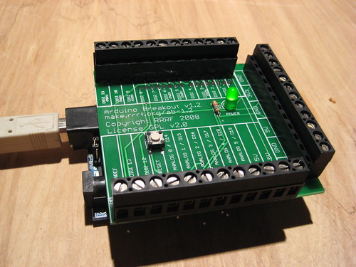
The Arduino Breakout Shield v1.2 is a really useful tool for Arduino based projects. It is a shield that plugs into the Arduino and transforms all the I/O pins into screw terminals. (plus lots of GND/3.3v/5V/input voltage pins!)
This is the latest incremental improvement, and the board feels pretty polished now. It has every I/O pin, a reset button, and a power indicator LED. Barring any sort of unforseen bug, I'll be taking this one to production soon. Yay!
New Board: Temperature Sensor v1.1
I just finished the documentation on the new Temperature Sensor v1.1 board. This board is an incremental upgrade over the previous temperature sensor board. It adds screw terminals for easier formatting and is now written for the default 100K thermistor.
More anti-ooze

Inspired by Ed'n'Ian's blog below, I went home and made this. It is a nozzle with an 0.5mm sideways hole intersecting the 0.5mm nozzle hole. Into this goes a length of 0.5mm-diameter piano wire. When you shove it in by hand it stops the polymer flow instantly (even stalling the extruder motor if you leave that running). Pull it back 1mm and the flow restarts equally instantly.
It's really easy to make too:

The trick is to drill the sideways hole using the nozzle hole as a centre before you make the cone. You have to use a woodpecker cycle to clear the swarf and be very gentle to avoid breaking the bit. But if you do, it works fine.
Then you just put the finished part in a drill chuck, use a felt tip to draw a circle round just below where the hole emerges, spin the drill and file the cone up to that circle.
Now to add a solenoid to move it back and forth automatically...
Friday, April 18, 2008
RepRap prints a child

This is for anyone who doubts the z-axis. Ian's son, Johnny, weighs 17.5 kilos. Admittedly the axis will only drive Johnny down and not up, but that's the way RP goes anyway.
We did tests on other humans and found Darwin to have a lifting capacity of about 7kg. Perfect for babies.
Shaving The Yak
As part of this, due to an amazing piece of Yak Shaving, I have now committed the plywood RepRap files in SVG format to Sourceforge. They're not complete, and there is no changelog. So obviously, that needs to be fixed for a start!
The original 4mm ply design is there, my 4.4mm attempts so far are there, and an MDF-based design that's not very Darwin-compatible is in the development stages. I haven't tried printing that last one out on Ponoko yet, and it's only half complete.
But I'd really like to get the parts I've made on the real RepRap together into a working machine, so for the moment I've released these files in their incomplete state for the enthusiastic among you to tinker with. Enjoy.
Vik :v)
PS The brass cup for the metal extruder looks like it might be easily made by tapping into the end of a 3/4" or 1" brass piping endcap and bolting the barrel on.
Tuesday, April 15, 2008
Anti-ooze
Here's my original idea, the ball valve section is actually a cylinder which runs through the nozzle to a lever and solenoid:

It suffers from leak potential and precision machining. It took this to Ian and he had a much better idea... a washing machine style valve:

Much simpler to make than the first idea, and initial tests worked really well. No leakage. Developments to come...
Simple Hot Metal Valve

This is my prototype design for a field's metal extrude head. It uses the same brass tube that we use for the polymer extruder, and the same nozzle. The tube has a smaller silicone tube inside it and a notch filed in it. A solenoid clamps the silicone at the notch. There's a brass cup at the top full of field's metal (melting point 50oC). All the brass parts are heated by wrapping them in nichrome wire set in JB Weld in our usual way.
And it works! Here's the vid:
RepRap metal deposition head from Adrian Bowyer on Vimeo.
The heater (with no insulation) only needed a 50/50 PWM duty cycle at 12v to keep the metal molten, giving an average current about 600 mA.
Roll on electric circuits. Roll on electric circuits in full 3D...
Labels: extruder, fields metal, metal write head
Monday, April 14, 2008
An iPod in your Ford

My wife Christine bought a cheap iPod mount that clips into the air vent on her Ford Fiesta. But that means that she can't use the air vent, plus the iPod gets cooked when she has the car heater on.
The dash also has a place to clip coins in (presumably for bribing traffic policemen...) that she never uses. So I designed one of these in AoI and made it in my home RepRap machine:

It pretends to be three coins in the right places to fit in the coin-clip, plus a bracket onto which the holder can be bolted. The picture at the top shows it working.
The tombstone coins are a bit woolly as I'm just back from Oslo and didn't have time to reset my machine from the experiments I was doing before I went away.
Also see a blog from Ed and Ian on controlling polymer flow shortly...
The design for the bracket is in the RepRap repository here.
Labels: custom iPod clip
Saturday, April 12, 2008
RepRap in Oslo

With lots of hand-waving, obviously...
I was asked to give a keynote at Go Open 2008 in Oslo. The conference had other keynotes from the likes of Chris DiBona, the Open Source Program Manager at Google, and Simon Phipps, the Chief Open Source Officer at Sun. RepRap was well-received, and the conference as a whole was both very good and very well-organized. There should be a video, which I'll link from the RepRap video page as soon as it is available.
I had a little spare time, which I used to make contacts with a group who are concerned to shift free technology into the developing world (more on that if we can set up a collaboration), and also to make friends with a local:

Labels: conference, keynote
Some estimates...
If that is meaningful then if Chris printed a 40x40x20 block of HDPE at 50% fill one would expect that the curling at the corners which would have a distance from the block's centroid of 28.8 mm would be about 0.94 mm. The warping at the midline would remain at 0.47 mm, of course.
(No additional content at 3DReplicators.com)
Wednesday, April 09, 2008
A few thoughts on warping

The chart displays the amount of upward curling that could be expected from various polymers printed at several fill percentages at each end of a 40 mm bar with, iirc, a 10x10 cross-section.
Chris, if I've understood correctly, has been doing such tests with the notion of identifying polymers and fill rates which give the smallest amount of warping after they've been pulled off of a printable surface.
I've been toying with the idea of trying to correct for warping by printing on a convex surface. The brute force approach to this would be to develop a mathematical model for warping and then design a support rick for a particular piece that we wanted accordingly. This morning, however, I am wondering if we could simply center any print on a standard convex support rick, the curvature of which would be determined by the polymer being printed.
It would seem that the first idea to test would be to try to print Chris' standard bars on top of a loose-fill support rick that corrected for the expected warping. If that worked a few other issues would have to be looked at.
The first would be whether the aspect ratio in the xy plane made much of a difference to the curvature of the rick. If it didn't it would seem that we should double the width of Chris' standard bar a few times to get the shape of the convex curve of the rick.
The second would be to see if the depth (z dimension) of the printed object affected the convex surface curvature as well.
It would really be nice if we could get by with a standard convex support rick for printing parts of a particular polymer. It would certainly make life a lot simpler.
(No additional content at 3DReplicators.com)
Tuesday, April 08, 2008
Hello Slashdotters

We've been Slashdotted thanks to an article in ComputerWorld. A quick update on the state of play: I have now fabricated all the parts of the RepRap except the Z flag which is probably easier to just cut out of the side of a beer can. I've taken delivery of the steel rod for the frame, and the driver parts from Jaycar turned up this morning. So, all systems are go - except I have to be in Wellington for the next two days. The suspense is killing me!
GPL Note: Yes, we know the GPL doesn't cover hardware. That's why we're releasing hardware "In the spirit of" the GPL. We know about TAPR but it's not right for us at this point. It's complicated.
Vik :v)
Labels: full, parts, reprap, slashdot
Sunday, April 06, 2008
Granule extruder
 click the pic to get one big enough to see...
A couple of days ago Zach and Nophead independently came up with two important insights. Zach's was that, in order to make a granule extruder, you don't need a complicated auger to move the granules forward; you can just use a piston, like a syringe. Nophead's was that, if you want a tube that's hot at one end and cold at the other and strong you could use stainless steel (which has a very low thermal conductivity for a metal) and slap a heatsink on it at the point where you want it to go from hot to cold.
This prompted me to sketch out the above design for a granule extruder. The extrude nozzle is on the left, made out of a brass fitting screwed to the 8mm I.D. stainless tube. We wrap nichrome heater wire round that and that end of the tube to cook them up (there would also be heat insulation round this section - not shown).
A bit to the right is the heatsink, which gives the transition from hot to cold. Around here the polymer should go from a melt to granules. This phase boundary is important, because it is here that air bubbles get more-or-less automatically excluded.
If we can easily get 8mm internal diameter stainless tube (anyone know where?), we can just use a length of the standard 8mm studding that forms Darwin's frame as the piston. The piston stays cold at all times; when it gets near the melt region (detected by an optoswitch - not shown) it is retracted and a new charge of granules falls in front of it from the hopper.
Recently Ian measured the force needed to push polymer through our standard 3mm filament extruder - it was about 10 N. This means that this device should need about 70 N to give the same pressure. The drive is a worm gear turning an M8 nut against a force transducer that measures that force.
Flow has to be controlled by force rather than the distance the piston moves, because the melting of the granules into the melt is an unpredictable process. [Also one potential problem with this design may be overrun: even when you take the pressure off, the nozzle may continue to extrude for a while.]
At the right hand end is a nut running in a hexagonal channel. This is soldered on the end of the M8 studding and stops it rotating.
I think the whole thing needs to be horizontal rather than vertical (which might be mechanically simpler) because my earlier granule extrusion experiments showed that the mere convection of heat up the tube was enough to melt the polymer all the way up. But a simple experment with a heated tube and heatsink full of non-moving granules should show if it really does need to be horizontal.
I'm off to the Go Open 2008 Conference in Oslo in a few hours to spread the RepRap word. I'm back next weekend, when - unless anyone can think of a good reason why this won't work - I might try to put one together.
I'm also experimenting with a very very simple design for a field's metal extruder for electrical circuitry that's waiting for the transatlantic postman to lay some insulated nichrome wire on me from the RRRF Store.
Watch this space for news on both when I get back.
Friday, April 04, 2008
RepRap extruder does ABS
Its warping is a lot less than HDPE and a bit more than PCL, but the main advantages are that the die swell is low and the filament is very compliant. It follows the head movement accurately even when extruding 0.5mm filament at 16mm/s. That gives objects good definition and sharp corners.

It is also much harder than the other two plastics and makes very rigid objects.
Read all the details here: hydraraptor.blogspot.com/2008/04/absolution and for comparison my evaluation of PCL is here: hydraraptor.blogspot.com/2008/03/chalk-and-cheese.
Labels: ABS
Ponoko.com lasercut kit, strike 2

The folks at Ponoko are being very patient with me and have run off a second attempt at getting the RepRap printed out on their laser cutting service. I'm not as good at this as Toby Borland who did the original lasercut conversion. Ponoko did their job fine; I goofed again, hence a few nibbled edges in the photo where parts almost fit together.
But this run also produced parts that DO fit together. We also managed to include 2 x 9mm MDF baseplates with cutouts for the wiping mechanism (no mechanism bits yet though) instead of just one in acrylic. I used the cutout space to print some test parts in that normally would require laminating. If they work, that'll save money and effort as you pay per cut and we can get the kit cost down further. I think we shaved US$40-50 off the previous run, and I hope to do the same again.

Most of the parts now have helpful little labels etched onto them, letting you know which tab fits in what slot. One of the more interesting set of goofs is that I accidentally told the laser to cut some lettering right through (and vice versa where some cut lines are only etched). So if you see lettering on the reverse of the cut sheets, you know it's a bad sign (marked in red on this photo, dropped sweet wrapper marked in blue). Maybe they parts will work if the 'D' and 'O' gaps are loaded with epoxy...
The ball-chain gears look like they'll work for 90 degrees of drive - just. I'll tweak them a bit more, and thicken the base of the gear teeth where the laser cut more than I thought it would. All being well, I'll be talking to the awfully nice Ponoko people in a week or so to run my third - and hopefully final - prototyping run. Meanwhile, I have what feels like a 1,000 piece 3D jigsaw to assemble and I have to correct the bits that don't fit!
Vik :v)
PS Missed the Y carriage out altogether Garrr!
Thursday, April 03, 2008
Z Motor Adaptor Plate
 I've made an adaptor plate (it's in SVN) to allow single shaft stepper motors to be used on the Z axis. It's not a tricky part - you could hack it out of plywood or aluminium fairly easily if necessary. There are also slots in it to allow the mounting of smaller stepper motors, though I don't know yet if they'll turn the Z axis - we'll find out when I get the drivers for the Arduino stepper board.
The incarnation shown in the photo bends a little when fully stressed up, so I've thickened it by an extra mm since then.
Yes the corner bracket is fairly crappy, but the crappy side isn't used on the Z axis' corner so I'm using it anyway and saving myself another 7 hours of printing.
Vik :v)
Labels: adaptor, plate, reprap
Wednesday, April 02, 2008
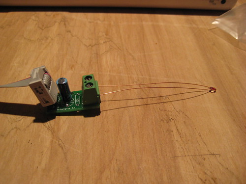
New Board: Thermocouple Sensor v1.0
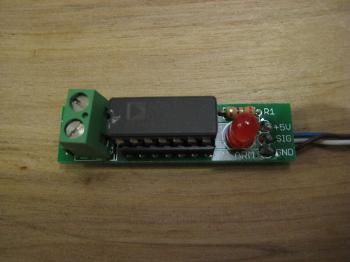 This new board is a cool, 'experimental' temperature sensor based on a Type K thermocouple, and the AD595 chip. It is very useful. It makes temperature measurement really easy, can easily measure up to 500C with the Arduino (up to 1300C with a bit of extra work). Read about it on the wiki.
It's not an official set of RepRap electronics, but can easily be integrated with the Arduino code. This board is intended for people who are interested in doing advanced research, are fed up with thermistor problems, or just want better temperature measurement.
It's available now from the RRRF store (kit coming soon!)
New Board: Arduino Breakout v1.1
 I recently finished a new board for the RepRap arsenal: its a 'breakout shield' for the Arduino that gives you screw terminal headers for all the pins (as well as extra terminals for all the voltages/gnd.)
Its quite useful, and available from the RRRF store (kit coming soon!)
![]()