Sunday, September 30, 2007
Cheers! Another Minimug Emerges.

Here's me with the finished PLA minimug, and the Darwin that made it. Oh, and a rather fine bottle of Ballantine's 30 year old scotch. There now appear to be two 1.0 Darwin RepRap's in existence.
I've started trying to make RepRap parts with it, but being single-material it can't make them all just yet.
Vik :v)
Friday, September 28, 2007
The extruder lives - again

And the Darwin produces a minimug; well, nearly. It's not watertight and has a lot of stringy bits in it. Not far off though. The Z axis is starting to smooth out a bit and the extruder is behaving very well now, if a little slower than I'd hoped.
The blown nichrome was right on the surface where the wire entered the plaster jacket. I suspect metal fatigue. Still, I dug out a few mm of nichrome (the 'pelican' insulation had disintegrated near the break) from the jacket and fired it up again. Heh, not forgetting to do the PTFE clamp back up...
[Breaking News: Watertight minimug now exists. Pictures of traditional toasting tomorrow.]
Must also pay some attention to family this weekend.
Vik :v)
Thursday, September 27, 2007
Running smoothly - for 5 minutes

I think I've got the PLA extrusion fixed. This is my setup, complete with little G-clamp to add additional pressure. I'm using a massive "that's not a motor - this is a motor!" 12V motor frankensteined on to the standard gearbox using CAPA. I left the fan from the little motor there in case the CAPA decided to get warm...
The extruder now purrs like a kitten with no feed issues whatsoever. The extra switch (red DPDT above large fan) is so I can switch the thermistor between the controller and my meter when calibrating.
But.
My extruder heater just went orange and popped - just after I sent my spare to Adrian! No, Adrian, don't rush it back - I need to build another anyway :) Still, it goes no more. Fair enough; it's an elderly specimen and I can do better. I also know to use a 20% lower resistance than specified for the standard extruder heater, as it won't quite work with PLA on a real 12V supply (it needs 14V).
A small bit of background: It's made from "pelican wire" without secondary insulation, if I recall correctly. I checked with a multimeter and it's not a short to the barrel. Might have to go back to BBQ paint and standard wire for PLA.
Vik :v)
Wednesday, September 26, 2007
Object file release updates
I've modded the release packages for the Cartesian bot and the Mk2 polymer extruder to cater for the new quickfit interface, and some minor revisions. The packages are available on SourceForge. Mods as follows:
Cartesian Bot 1.0.2, new STL's:
Z-toothed-pulley-rim.stl
Z-opto-flag.stl
Y-motor-coupling.stl
X-PCB-bracket.stl
X-carriage.STL
Extruder-quickfit-latch.STL
Extruder-quickfit-dock.STL
Bearing-insert-360-run.stl
Diagonal-tie-bracket.stl
Bearing-insert-180-Z.stl
Bearing-insert-180-X.stl
Thermoplast Extruder 1.0.1, new STL's:
quickfit-clamp.stl
Smokin' The Gear
I darned well blew another extruder motor. Even though it had a nice CPU fan on it to cool it down, it still popped. I am pushing PLA here, not the standard CAPA filament, so the equipment abuse factor is fairly high.
Fortunately, Forrest has been kind enough to supply me with several motors from his collection, so I'll strap in a beefier one and see if I can get pumping the PLA again.
I've squished more CAPA over the bearings to hold them in place, and at least they don't seem to be twisting around into the filament any more. I am generating quite a bit of PLA dust though!
Vik :v)
Monday, September 24, 2007
Moulding RepRaps
More news on moulding the parts of RepRap to get the first machines out there fast: I just made the tie bracket (one of the parts of Darwin that you need a lot of for one machine):

On the left is the original RP part, on the right is the moulded one. What you can't really see here are the complicated internal cavities.

I started by super-gluing on a gate (white cone - plastic rod through a pencil sharpener) and a riser (thin white rod) to the original part. Then I added sticky tape to define a mould split line and put two 8mm rods through the holes. I then put an M5 bolt through an internal trapped nut to hold the rods.
I put the lot in a plastic box and poured in Viscolo 22 liquid silicone from Tomps. I should say immediately that this is a fantastic moulding compound. It is very inviscid when pouring, which means that bubbles come out so you don't need to do the moulding in a vacuum. If only it were transparent (so you could see the tape mould split to cut to it after it's set) it'd be perfect.

Here are the resulting mould cut to the split and with the rods and M5 bolt put back in. Note the nut floating on the bolt - that's going to get incorporated in the casting and become a trapped nut. I covered the rods and the bolt (but not the nut) in a thin film of silicone grease. Then I poured the resin, which was Tomps polyurethane fast-cast.
Here it is solidifying:

I simply cannot rave enough about this resin... It is the consistency of milk when mixed, so it pours really easily, and it sets in half an hour at room temperature. It is just a perfect material.
The result was a solid workable bracket, with an embedded nut and all the internal cavities needed.
Sunday, September 23, 2007
Waitakere Darwin 1.0 Printing in PLA

I've got my Darwin printing in PLA. I had to fiddle the software a bit - reinstate Z-axis speed, and add some bits to ignore ludicrous temperature values.
Hardware required more fiddling: I Fitted a fan over the extruder motor to keep it cool as PLA needs a lot of driving. I used a half-round file to sharpen up the thread on the extruder drive, and I've added the dangly filament holder.
I tried doing another PLA flask, but the extruder jammed after 5 layers. I think the bearings are rotating and digging in to the filament. Might need to make new ones.
Vik :v)
Thursday, September 20, 2007
We Strive To Improve...
Here's an idea or 3 I've been kicking around to improve the Darwin design. Maybe they'll have to wait for Mendel but here goes:
1. Y Belt gear to outside
Move the Y belt gear furthest from the Y motor to the other side of the
Y axis bearing. This probably means mounting the Y belt clamps on the X
axis square jig, but avoids filing that long flat - the gear now just
slips on the end.
2. Z motor on top
Move the Z motor to the diametrically opposite corner and take it
outside the build area. We gain another 60mm of build height - or save
700mm of steel rod & studding. Forrest suggests we also use the shaft coming out the front, not the back.
3. Beaded belt for belt drive.
The right toothed belt is hard to source and expensive. We might be able to use the
sort of stuff used for window blinds and securing vicious attack biros in the bank's foyer. Some testing will be needed, as will new methods of splicing the stuff. Here's an industrial supplier: http://www.raymortool.com/Gen_Info.html
Right, enough brainstorm. Back to testing the new extruder temperature code.
Vik :v)
Labels: beaded belt, improvements, reprap
Wednesday, September 19, 2007
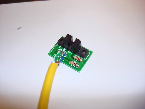
Trivial Update Post: Opto Enstop Docs
 Some have complained that the posts here are somewhat sporadic and they'd like to read more, and I agree with them. It can give the illusion that we aren't working very hard, when in fact we are working very hard on RepRap. So hard that sometimes we don't have time to post on the blog. We're going to try and change that by ideally posting once a day with something that has changed, or been worked on.
Today, I updated the Opto Endstop documentation page. It's almost complete, I just need to take a couple more pictures, and write up some testing info to go along with it. It's a pretty basic page, but now it is much nicer and up to date with the current project status.
Tuesday, September 18, 2007
PowerComms v1.3.0 Beta
 We've been working on the design for the PowerComms v1.3.0 board for a few weeks now. Once the design was to a stable state, the RRRF ordered a small batch of boards from our PCB house. We got 20 boards back, and I'd like to offer these boards (for free!!!) to people interested in helping out with the project.
These are only the PCB's, and you'll have to pay for shipping, as well as the components to put in them, but hey... you're getting a free PCB!!
For more information, check out the RRRF store detail page.
If you want one, simply buy it from the store. We hope that you contribute back to the project with build pictures, documentation, and by testing. You're not required to, but we'd sure as heck appreciate it.
Keep in mind that this is a beta version of the board, and we make even fewer guarantees than normal about it working. (Hint: we make no guarantees about anything, hehe.)
Monday, September 17, 2007
Darwin's bits
Had a slow paper-writing day, but on the plus side got a Darwin build finished off the Strat. I thought I'd get creative on a break with all its RP bits ;-)

[Thought: if science is about understanding the universe, is art about understanding the people in it?]

[Thought: if science is about understanding the universe, is art about understanding the people in it?]
Extruder temperature bug (almost) eliminated
For ages (sorry) the extruder's temperature measuring function hasn't been working properly, giving dud low readings intermittently.
I spent the weekend working on the code and have improved both the Java end and the PIC C end. (I have updated both in the svn trunk and also updated Simon's autoconf-firmware branch).
Here's a summary of what I've done:
JAVA:
The Java now takes a majority vote between the last three temperature measurements; this reduces the impact of isolated dud measurements (the temperature can never really change very fast, because of thermal inertia).
PIC C:
The PIC C code now detects when the capacitor charge/discharge timings are interrupted and discards such measurements, only keeping clean ones. Unfortunately, with largish capacitors, the measurements are always interrupted because of the times taken to charge and discharge, so this means reducing the capacitor otherwise one never gets a reading... For the standard thermistor (beta = 3480; Rz = 29K) this means a capacitor of 10nF. I have modified the calculator in the wiki to put in a fudge factor to give this and have changed the extruder controller PCB wiki page to say this, but more thought there is needed.
I have reduced the frequency of the heater PWM interrupts by reducing the value of HEATER_PWM_PERIOD from 255 to 253 'to calm things down'.
I have set the main loop so that it doesn't call the temperature measuring function each time round, as that used to mean that the PIC spent all its time in that function, making large the probability that it would be interrupted and cause trouble*. The heater pwm function now sets a flag, and the temperature measurement function just gets called once after that flag is set. (Having the function instead called as a result of the heater pwm interrupt would cause further trouble, I suspect, so I didn't do that, even though it's more obvious.) This means that the extruder PIC spends most of its time spinning in its main loop waiting for something to happen.
*Actually this is a statistically spurious argument: if interrupts occur in a Poisson distribution (which they don't, but never mind) then the function is just as likely to be interrupted, but any given interrupt is less likely to interrupt it. As it is, interrupts are quasi-regular, which has the same effect. But anyway it seems to work better...
RESULTS:
All this seems to make the temperature readings a lot more stable. But you still get the occasional dud. I suspect that this is a timing issue between my majority-of-three vote in the Java and the interrupt rate in the PIC. The Java is taking its readings too rapidly - more experiments will be done...
The much-reduced capacitor value means that the temperature auto-ranging runs vRefFactor up to 15, where it more-or-less stays. This is probably a bad thing - more experiments will be done...
Labels: Extruder temperature bug
Friday, September 14, 2007
More on the granule extruder
The main problem with the extruder was the conduction of heat up the brass and copper screw auger. I decided to make one from a less conductive material - JB-Weld. Here are the initial results. I cast an ordinary 13 mm drill bit in silicone, took it out, then injected mixed JB Weld from the bottom of the cavity with a syringe (to exclude bubbles):

And here it is (with the original drill) after being cut out of the mould:

I probably won't use a drill as the master finally (it's pitch is too coarse, and you have to turn it anti-clockwise, which tends to loosen things), but this shows that you can cast from virtually any helical shape to get what you want.
Labels: extruder design
Sunday, September 09, 2007
Extruding from granules
I was so impressed by the EVA-granule extruder made by Timothy Nixon and Adrian Tan of the School of Mechanical Engineering, University of Adelaide, Australia for Fab@Home (see this link) that I decided to revisit something Forrest and I did almost two years ago (see the blog for Friday, February 17, 2006), nick extra ideas from the Aussies, and have a go at designing one for RepRap to work with polycaprolactone.
Here it is working:

The advantage is, of course, that all thermoplastic polymers are available in bulk at very low cost in granules - it's the standard form. Getting 3mm filament (which is what RepRap currently uses) is not difficult - many companies will do it - but it does add slightly to material costs.
You can find details on the RepRap wiki here. It needs more work, but it'd definitely be a useful addition.
Saturday, September 08, 2007
Volunteers needed!

I have just made an Art of Illusion version (right) of the design for the new quick-change extruder from SolidEdge (left - SE can't get its triangle normals right...). I have simplified some features, but it is functionally identical.
The good news is that it was really quick and easy to do. I just imported the STL file out of SE that we used to make it into AoI, coloured it a stand-out colour (unlike the picture above), dragged out a bunch of blocks and cylinderes to the same size (really easy if you zoom in - you can get the accuracy much better than the 0.1 mm or so that is needed), then booleaned them together.
Does anyone want to do this for the parts of the Darwin design on Sourceforge? They're at:
http://sourceforge.net/project/showfiles.php?group_id=159590
(Check out the latest zip file of Cartesian Bot.) All you need is a computer with Art of Illusion running on it.
This would be a real help to the project, as then anyone would be able to edit the Darwin design. There are hints and conventions for using AoI on RepRap at
http://reprap.org/bin/view/Main/AoI
If you can help out, send me an e-mail at:
A dot Bowyer at bath dot ac dot uk
with the obvious substitutions.
Thanks!
Labels: darwin AoI conversion
![]()