Thursday, April 12, 2012
More Printed Circuitry
It’s been quite a while since I've done an update on the metal printing front, so I thought I'd do an update of where we are. In my last blog post I set out about choosing a low melting point metal which would have some unusual properties which would help with printability - mainly choosing a temperature which would minimise damage to our traditionally printed plastic components on to which our metal would be deposited, and also using a non-eutectic to attempt to minimise the effects of surface tension.
One of the main problems I previously had was solubility. Running molten metals were acting as solvents for my heated nozzle - resulting in the nozzle slowly dissolving during a print. At the end of my last post I'd just tried using anodising to create a strong oxide layer on the surface of an aluminium nozzle to protect it, and that the results were promising after little running - I've done hundreds of hours printing since and as far as I can tell no damage has been done and its still in its original condition. I'd anticipate that a stainless steel nozzle would also be useable as it also has a strong oxide layer.
Previously the plastic and metal were printed on separate machines. Anyway, I've heavily modified my X carriage to take one Bowden extruder (for the plastic) and one "standard" extruder for the metal such that I can (in theory) do one shot printing. The metal extruder is fairly standard, the only major modifications are the inclusion of an O ring to reduce leaking, and running the PEEK insulator right to the end of extruder to minimise the melt zone - the result is a slow extruder - I'm currently printing track at about 100mm/min - but hopefully one which we have the most control over.


I printed the above about a month or so ago. The plastic housing contains a female hole for supporting an ATMEL644P PDIP chip, as found in our Sanguino electronics. The metal tracks are housed within 0.7x0.25 rectangular channels. Surface tension would suggest that the metal would naturally want to take a circular cross section - however given the size of the track I'd be unable to get anywhere near this hence the rectangles. The component was inserted into the plastic and the metal track automatically deposited on top before being covered with more plastic. Importantly we can see that the plastic extruder isn't excessively melting the metal tracks when covered.
Since that print I've been battling a few bugs with the setup - namely reliably keeping the offset between my plastic and metal extruder - the sprung mounts flexed under the compression of the bowden cable - and getting somewhere near a reliable metal filament drive - It turns out my standard hobbed bolt I used to do the driving wasn't good enough - I think the problem was due increased wear of the bolt due to the higher stiffness/hardness of the filament and a lack of compliance in the filament reducing the contact area. Anyway creating a new stainless steel hobbed bolt seems to have improved things massively:

Here is a stab at the Arduino compatible Sanguino board (albeit simplified). It's pretty standard except we've removed the reset circuitry and alot of the pins. We still have 4 controllable pins, one for the LED and three spare for something fun in future. Once again the plastic was printed before dropping in pre-tinned components and finally printing the metal tracks. I have previously done some tests which show we need to have a radius on each corners of printed tracks, ideally at least 1.5mm, but for compactness I squared these off resulting in poorer quality but nevertheless its quite a big step forward from where we were a few years ago. Four extra tracks are required on a second layer to get the circuit fully working; I've done this manually for the time being. In addition I had to manually solder in 2/3 pins as the track had not connected properly, however I think I can correct this by extending sections of track beyond their required endpoints and utilising the bigger radii at corners that I've already mentioned. It's still a little blobby, but nevertheless here it is working running a simple blink program, although we can still reflash the chip to do something else with the spare pins:
Labels: Printed electronics


Sunday, February 25, 2007
Low-melting-point alloys
I've always thought that the problem with this might be that the (admittedly small) melt cavity inside the head would simply drain out the bottom uncontrollably.

But the other day my student who's working on this, Mike Samuel, had a brilliant idea: why not replace the cavity with a small heated button with a fine extrusion hole through it, then just touch the metal on the back when you want it to melt and extrude? The extrusion system already has a mechanism to back the rod off; this would remove it from the hot-spot and stop the flow.
The head would be like the above. The brass part would have a heating coil, like the ordinary extruder, and a thermistor to measure its temperature. The Wood's metal rod would be fed into the top by the existing transport mechanism that's used for the 3 mm polymer rod we use. And all this would use exactly the same electronics and software to drive it that we already have.
So I tried to make some 3 mm Wood's metal rod.
My first experiment was rubbish: I had a small crucible with a 3mm hole in the bottom heated by a soldering iron. The hole led through an insulating block with a 3 mm hole to a cooled section with another 3mm hole, where I thought the metal would solidify and be able to be pulled through - pulltrusion, as it's called. The whole thing locked up frozen solid, and nothing would move anywhere.
Then I looked at the silicone tubes I was using to carry the cooling water. Dang me if they weren't 3mm internal diameter. I put one on a funnel with a clothes-peg at the other end, heated them all in a beaker of boiling water, took them out and quickly hung them up, then poured in the Wood's metal:

After it had cooled I just sliced away the silicone tube with a scalpel, which left a perfect shiny rod:

I measured it: 2.95 mm, all the way down :-))
Labels: Field's metal, RepRap electronics, Wood's metal
Sunday, February 19, 2006
Saturday afternoon filament extruder experiments
I ran more experiments today using my 1/4th inch (6.35 mm) ID screw pump. I began with the metal drill bit that I hadn’t used in yesterday’s experiments.
Metal drill bit
Maple syrup
As you recall, water did not pump well at all in the rig.
Semolina grains
I tested the configuration with uncooked semolina grains. The metal drill bit pumped that media wonderfully. I tried putting my fingertip over the end of the barrel. The semolina collected behind my finger and the drill bit was thrust back out of the rear of the barrel with considerable force. A very solid plug of semolina grains were packed in the barrel. I had to literally drill that plug out.
CAPA 6800 pellets.
I fed polymer pellets into the “t” junction. The metal drill bit tended to chop these up and pump them to the end of the barrel. Most, however, of the pellets were thrown back out of the hopper. The pellets that emerged from the barrel were mangled rather than chopped into proper bits.
Visual inspection indicated that the pellets were considerably larger than the helical passage in the metal drill bit. The pellets had to be deformed or chopped until they could be fitted into that passage.
Wood auger bit
I repeated the experiments with semolina grains and polymer pellets. The wood auger afforded a considerably larger passage than the metal drill bit did. Both semolina grains and polymer pellets were pumped effectively. The polymer pellets were not mangled as they had been with the metal drill bit.
Observations
Considerable torque forces are being developed when tough polymer pellets are being cut and mangled. Hanging on to the barrel with a spanner is not practical. A frame holding both the barrel and the drill is needed.
Friday, February 17, 2006
Initial experiments on filament extruder 2.0
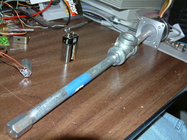
I built up a rig like the one that Galacticroot did. I used 1/4 inch ID fittings to do it which makes for a much cheaper and more dimunitive pump that Galacticroot had.

Metal bits
The first thing I tried was a 1/4 inch metal bit. I used my electric drill for power and initially tried to pump water with it. You can see it and the barrel that housed it at the top of the picture. The first thing I noticed was that the metal bit pump would not self-prime. I primed the pump and ran it again. At that point I observed that the metal bit would not pump water under any circumstances. Indeed, it seemed to slow down the natural flow of water through the pump. Reversing the rotation of the bit made no difference save that a bit of water began to flow out of the pump at the end closest to the drill and the flow out of the extruder hole pretty much stopped.
At that point I decided that the fit of the drill in the barrel was too loose. I greased the barrel heavily with petroleum grease, reprimed the pump and tried again. There was no useful pumping being done. I observed a tiny bit of pumping in the reverse direction but nothing significant.
Having failed I went back to the literature. The first thing I noticed is that the diagrams I had showed the flight (thread) length on such drawings as I had pretty much identical to the gross diameter of the screw.
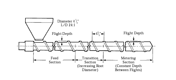 On our 1/4 inch metal drill the flight length was twice (1/2 inch) the diameter. As well, the proportional depth of the threads was much, much larger than what you encountered on a polymer pumping screw. Indeed, there was little core shaft as such in a metal drill.
Wood augers
Next, I tried a wood auger. The flight length of the wood auger was 3/8th inch for the 1/4 inch diameter as opposed to 1/2 inch found in the metal bit. The wood auger was also much longer with many more flights over its length. I acquired a longer barrel and rebuilt the pump. That configuration can be seen in the picture above.
I installed the wood auger, greased the assembly, primed the pump and began again. With the wood auger I got an appreciable pumping action, but nothing useful. Looking more closely at the wood auger it was easy to see that the depth of the flight was proportionally huge compared to a polymer pump screw. There was again almost no core to this auger.
Masonry bits
There are several types of masonry bits. Revisiting the local hardware store I encountered one proportionally almost identical in form to a polymer pump. Sadly, it was 3/16ths inch rather than 1/4. All of the other masonry bits were simple twisted rods and apparently useless.
In the morning I will visit a much larger hardware store and see if I can acquire proper masonry bit to continue the experiments.
Monday, September 04, 2006
Use of Castable Bearings in RepRap
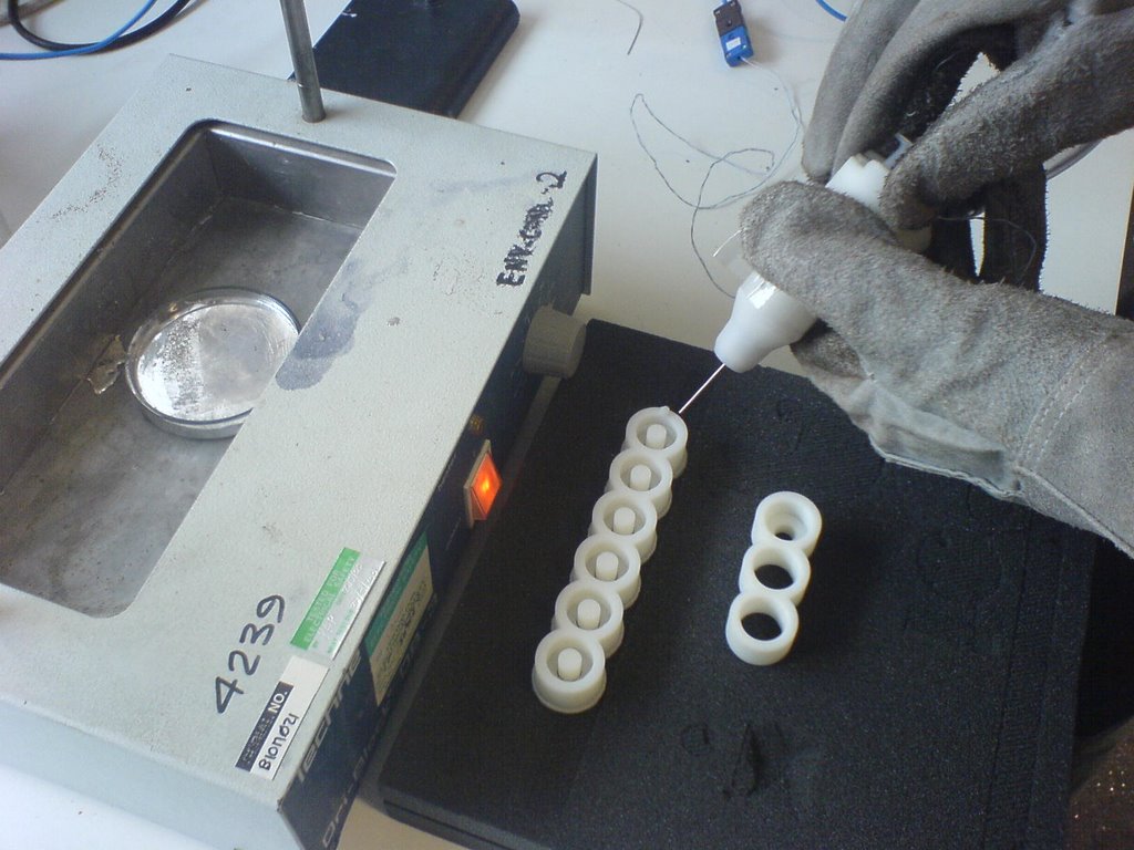
Apologies for the delay in posting this....
A few weeks ago I attempted to produce some bearings using Field's metal and RP moulds. The aim was to prove that it was possible for a RepRap machine to produce its own bearings, as Field's metal melts at approximately 70 degrees celcius......
I tried 2 methods
1. Casting the metal in a mould with the 8mm steel bar in situ, using silicone grease as a spacer.
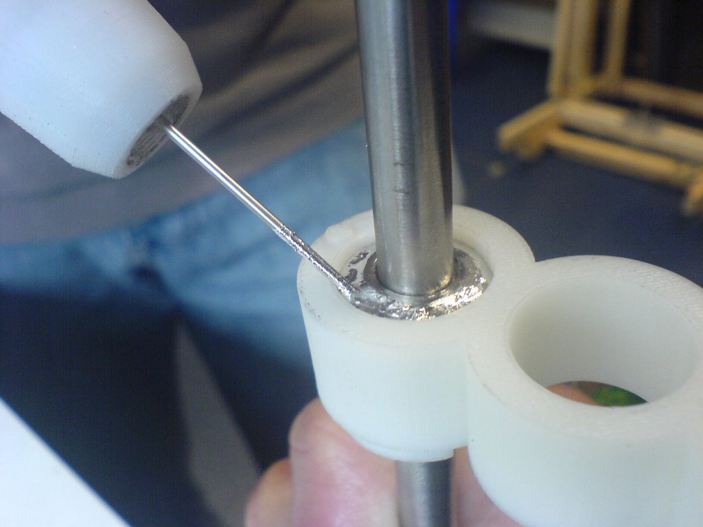
2. Casting the metal in a mould with a plug that could be hammered through once the metal had solidified.

Method 1 failed as a bearing (but would be good as a locating/fixing mechanism - ie calibrate
machine, then set all joints in metal)
Method 2 produced some nice bearings..... (Only tested by hand so far)
Method 1 - 3 hole mould and cap used to locate the rod and seal the base.
Method 2 - 6 hole mould with varying plug diameters, the support material needs to be left on to hold the plug in place.

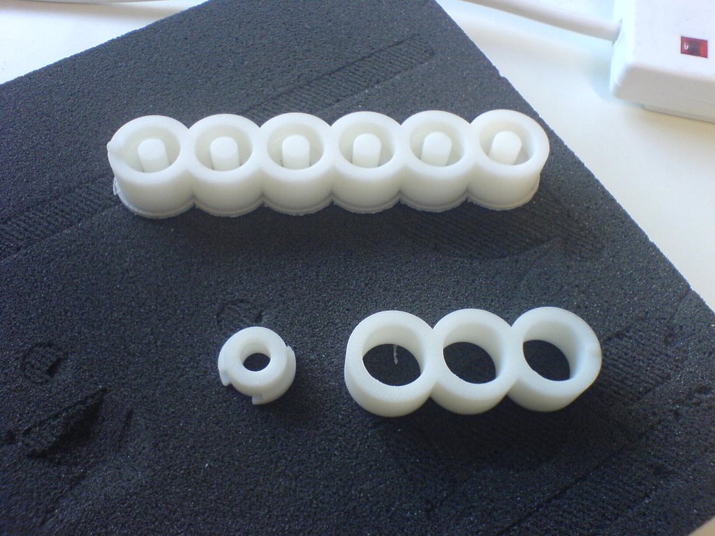
The best results were achieved with a centre plug diameter of 8.2mm (to fit an 8mm bar)
Will be performing some basic tests on them this week
Fulll report available if anyone is interested
Sunday, May 14, 2006
Busy weeked with little to show
* Progress the virtual comms and testing infrastructure (see svn branch), which will soon allow me to complete the remainder of the comms infrastructure. This will eliminate those occasional pesky errors.
* Updated my old graycode wheel perl script and put it into the reprap subversion repository. See reprap/misc/graycode in subversion.
* Using new graycode script, produced a template for a bi-directional position sensor for a DC motor controller.
* Tried out my previously imaginery process for turning PC artwork into plastic objects, pre-reprap. Potentially a useful process for "repstrapping" with kitchen level technology.
* Some work on reprap application to eliminate most of the hard coded magic values and make them customisable via the preferences screen.
* Tested my old thermoplastic bushing idea for my old repstrap design. Mixed success. It fits so perfectly that it doesn't turn very easily, but it certainly removes any play in the threaded rod. Needs more work...

This is what my 2-bit graycode bi-directional position sensor currently looks like. It's so simple it could just as easily have been created by hand, but using the script allows for very simple changes to diameter, spacings, etc. In fact, these are the parameters for the graycode script. It's fairly versatile:
* Number of bits (arbitrary number)
* Wheel dimension (mm)
* Inner dimension (mm)
* Strut size (mm)
* Span (degrees). For angle sensors, it's often useful to use less than the full 360 degrees.
* Stagger (~mm). Stagger between sensor positions. This allows bulkier sensors to be used and the graycode rings are offset. The application also produces a cutting/placement guide that should where the sensors should be placed, which is pretty essential when staggering.
* Resolution (dpi)
* Portion. Fraction of wheel to include (entire wheel is not necessary if used for angle measurement and using less than 360 degree span)
* Reps. The number of repeats of the graycode pattern around the wheel. This is the new feature needed to make a mechanically balanced wheel for a fast turning position encoder.
I started to add STL support a while back, but that's not even close to complete. The primary output is a bitmap ready for printing on a laser printer.
My conceptual process to turn these into actual plastic objects was:
1. Print out object onto tracing paper with a good laser printer (new toner). Inkjets don't work as the inks are UV transparent.
2. Take a piece of thin steel, and spray it with PCB photo-resist. Bake dry for impatient people like me.
3. Place tracing paper pattern on metal. Cover with thing sheet of transparent plastic (not glass which is UV opaque) to hold pattern close to surface. I used the plastic from a CD cover, whatever that is.
4. Blast with UV light
5. Use developer to bring out the pattern on the metal
6. Using electrolysis, "melt" away the unprotected part of the pattern, leaving a thin metal version of the pattern. Alternatively use copper sheet, and use ferric chloride to remove unwanted metal.
7. Press metal pattern into molding plasticine. Pressing it deeper makes a wider part.
8. Create plaster of paris mold from plasticine and let it dry.
9. Melt plastic into mold
My goal was to produce one of the gray code sensor wheels and Forrest's sample involute gear pattern.
I tested steps 1-5 but it seems my photo-resist is a bit too old now. In fact it's quite a few years beyond it's "best by" date, so it's time to order some more. The patterns were not holding well enough for me to carry out the remainder of the steps. I will try again when I get some more photo resist, but all the local suppliers seem to have stopped selling it. I'll try RS.
I tested step 6 using several different electrolytes. Plain salt (NaCl) was the fastest but has the downside that it produces some chlorine gas, so ventilation is a good idea. It doesn't need much salt though. I hand painted a pattern onto a piece of metal, and the pattern was cut out with good fidelity. It takes quite a few hours to cut, so you have to have some patience. It makes the more conventional ferric chloride approach more appealing if I find or make some plain copper sheet. I have lots of ferric chrloride, so I might try that next time. The electrolysis approach produces nice steel templates and just seemed cooler :)
I have previously tested steps 7 to 9 using PLA to produce some gears. It works quite nicely but destroys the plaster mold so it can only be used once. It also takes a bit of scraping to get excess plaster off the gear before it will work nicely.
So all steps tested, but not quite working yet.
