Friday, June 24, 2011
A new approach to printing metals
There have been numerous attempts to print conductors. Fab@home, Ed Sells and myself have all tried it previously with very limited success. Whilst I've been able to print a basic circuit from solder, we were unable to achieve the resolution to produce anything but the most simplistic circuit board. Forrest Higgs and others have tried to identify a useful non-metallic conductive material but conductivity has always been fairly poor. Months ago I blogged about using Nickel Carbonyl powder for exactly this purpose. What I didn't blog about was an experiment I did mixing the nickel with a low melting point alloy. When molten resulting semi-solid material had significant viscosity and effects of surface tension seemed minimal. Just by stirring the mixture with spoon it was obvious to Adrian and myself that there was so much control that this like a suitable material to print conductors with.
I did actually make filament using this composite material using the old technique of casting into silicone tubing. I was betting on the mixture not separating due to the ridiculously small particle size of the nickel carbonyl (about 2 microns). Alas I was wrong, the mixture separated and the powder blocked the nozzle but the fundamental concept of using a semisolid to gain more control over the extrudate seemed like a good one. Logically this is perfectly sound, it could potentially alloy us to deposit material on top of this semi-solid material without it going completely fluid and losing its shape.
Fortunately non-eutectic alloys also offer this ability to have solid elements suspended within a molten liquid. Further they have the benefit that as the temperature increases the entire alloy completely melts thus we can further control the viscosity with temperature as well as the alloy composition.
After some thought I proposed that our ideal material would have a similar melting point to PLA/ABS such that when deposited on top a minimal amount of damage. I thought at the time (and this later proved to be wrong) that the alloy should be as viscous as I could achieve at the initial point the alloy melts; Then the material would have a gradual transition as the temperature is increased. I did have a hunt around but I was unable to find a material that I thought sufficiently these attributes. But we are now a community of at least 4000 machines, so I don't think its too impractical for us to do what any of the big commercial additive manufacturing companies would do and have our own alloy.
I decided to go for an alloy of tin, indium and bismuth few a few reasons. Firstly tin is comparatively cheap, so I was hoping to get the properties we need with very little amounts of indium and bismuth. Secondly indium tends to lower the surface tension of molten alloys,thirdly and most importantly there is a lot of data on the melting point of alloys containing these elements so it'd be fairly easy to tune it to be comparable that of PLA/ABS. This would let us to print onto the plastic whilst causing minimal damage.

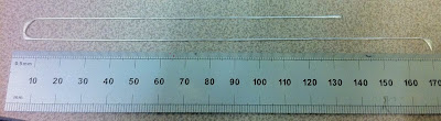
Above is the phase diagram for the system. My first alloy was 69.9% tin 29.2% bismuth and 0.9% indium (wt. %). Per kilogram the cost of the material was about £90 and I converted it to filament using the same casting trick. However this was a one off order so I anticipate it being substantially cheaper in quantity. The phase diagram predicted that this alloy should be about 80% solid when it begins to melt at about 130 deg C, and be fully molten by just under 200 deg.
The above was printed directly onto glass. I decided at the start of all this that if we are to produce useful circuits,we need to have sufficient control to build the track free form directly on top of PLA. Previously we needed channels to get any sort of the consistent track so this was already a big step forward. The rounding at the corner is due to the layer height being slightly off, which seems particularly critical when compared to plastics.
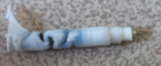
After the initial success, this is where the onslaught of problems began. Something I did not anticipate was that the alloy began to dissolve the brass nozzle due to solubility effects after very little use. In practice this meant that my extrusion parameters were constantly varying until the nozzle completely disappeared (this happened within about 15 meters of 3mm filament) . I also attempted an aluminium nozzle with the same result.
 At this point we were a bit stumped. Adrian suggested trying to make an all PTFE extruder (at least as far as the alloy was concerned). After several iterations the best solution was machining a PTFE liner with a built in nozzle. This was then surrounded by the usual brass heater etc like our hybrid extruders. Whilst I accepted this was not a long term solution, I thought that if we could get it to work in steady state conditions we could learn more about the process.
As it turns out with extended use the alloy was so viscous the alloy physically ripped the PTFE liner that serves perfectly well in our plastic extruders. Further it was apparent a black oxide was forming at the entrance to the nozzle. After a few hours use this ended up in a complete extruder failure.
After this failure it was fairly apparent that my initial alloy was far too aggressive. I therefore scaled it back to something that would operate at lower temperature (reducing oxidation times) whilst also having a lower viscosity to put less stress on the PTFE liner.
I guessed that a 50% liquid/solid ratio when the alloy begins to melt would be sufficient, and this turned out to be a composition of 57.5%Sn, 41.3%Bi, 1.2% In, again beginning to melt at 130deg but finishing by about 170. This proved much more reliable and with much less oxidation. It allowed me to produce the results below printed directly onto glass (it was flat before I peeled it off). The second image is particularly interesting as its three layers of track on top of one another, which would be required for tracks connected in parallel. I've also gotten similar results printing directly onto a PLA substrate, in this case it stuck fairly well but could be removed with a bit of force.


Whilst I've achieved fairly decent results with this setup, the transient performance was unsurprisingly poor given the insulating nature of the PTFE and the large melt zone I needed to get it to work. I therefore went back to solving the underlying problem of the alloy dissolving the nozzle. I've had ago at anodising an aluminium nozzle which is fairly easy, it just requires about 200 Vdc and the appropriate electrolyte. At the moment the nozzle design is still varying a bit, but I've taken pictures under a microscope both after anodising (first pic) and after extruding about 10m of 2mm filament. As far as I can tell there hasn't been any substantial wear.


After about 10 different extruder iterations (most I haven't mentioned here) It appears that the dissolving issue has therefore been solved. I haven't quite finished calibrating this extruder, but the latest results are below. Naturally its our logo, the track size is about 0.7mm in diameter. Given this was fairly successful I also tried doing it with infill, unfortunately it overheated as the filament didn't have chance to cool but I still think its quite successful. I need to try repeating this with cooling from a fan. I would have continued this build further but I can only make lengths of filament about 30cm long and changing them mid print is quite tricky,


Labels: Printing Conductors
Comments:
<< Home
I remember that some time ago someone designed a hot end for use with a glass nozzle. The nozzle was made by heating a glass tube with a blowtorch then pulling it to taper the end to a point. The end was then ground down until the opening had the desired diameter.
You might try using this type of nozzle to extrude your mixture, as it shouldn't dissolve the way brass does.
You might try using this type of nozzle to extrude your mixture, as it shouldn't dissolve the way brass does.

I'm curious. How is the alloy is dissolving the brass nozzle in the first place? What reaction is going on here?
Beautiful! At the Vancouver MakerFaire last weekend, probably every 5th visitor to my RepRap table ended up asking about printing metals. I can't wait to start experimenting with this!
VERY exciting progress! It's a smart move to dirty up the eutectic alloy to make it more viscous. Seems like well tuned formula could be the print medium of our digital futures of physical devices. Combine that with pick-n-place for components (also pick-n-place disassembly of obsolete devices) and we can start making complex electronic devices with an essentially single-click to print process!
This looks like a bit more complicated to create the ink, but It doesn't take any heat and seems quite durable...
http://news.illinois.edu/news/11/0628silver_pen_JenniferLewis.html
http://news.illinois.edu/news/11/0628silver_pen_JenniferLewis.html
This was a great link. Instead of melting metals why not just plot it all out with a pen?
What about powdered metals with a binding agent? Lay down the binding agent then put the powdered metal over the top of the binding agent? Would the binding agent remove any change of electrical conductivity?
What about powdered metals with a binding agent? Lay down the binding agent then put the powdered metal over the top of the binding agent? Would the binding agent remove any change of electrical conductivity?
I'm worried about all the embodied energy of reduced aluminum, should this alloy ever break through the oxide coating.
It might be worthwhile to look into a coating that stands up to this alloy for extended periods. I know there are lots of metals that simply don't dissolve in indium/gallium/tin alloys (mercury, for example: it and galinstan can be shaken up and will phase-separate). Maybe chrome-plated brass? Chrome plating services are reasonably cheap and accessible, and I don't think it's out of the question as a home enterprise, either.
It might be worthwhile to look into a coating that stands up to this alloy for extended periods. I know there are lots of metals that simply don't dissolve in indium/gallium/tin alloys (mercury, for example: it and galinstan can be shaken up and will phase-separate). Maybe chrome-plated brass? Chrome plating services are reasonably cheap and accessible, and I don't think it's out of the question as a home enterprise, either.
Have you considered using other materials for the nozzle such as ceramics or heat resistant plastics?
Have you considered coming at the problem from the opposite direction? Printing a very accurate pattern of groves then filling it with a fluid metal and sealing it with a second layer of plastic to make the circuit board, mercury is the first example that comes to mind but there are toxicity and expansion issues (obviously) so maybe make the groves double the size they need to be and pipe solder in then cut it down post printing to make a proper size tidy circuit board, there would be allot of waste but it would work as a proof of concept.
Have you considered coming at the problem from the opposite direction? Printing a very accurate pattern of groves then filling it with a fluid metal and sealing it with a second layer of plastic to make the circuit board, mercury is the first example that comes to mind but there are toxicity and expansion issues (obviously) so maybe make the groves double the size they need to be and pipe solder in then cut it down post printing to make a proper size tidy circuit board, there would be allot of waste but it would work as a proof of concept.
# posted by  : August 30, 2011 2:02 PM
: August 30, 2011 2:02 PM
Have you considered using other materials for the nozzle such as ceramics or heat resistant plastics?
Have you considered coming at the problem from the opposite direction?
Printing a very accurate pattern of groves then filling it with a fluid metal and sealing it with a second layer of plastic to make the circuit board, mercury is the first example that comes to mind but there are toxicity and expansion issues (obviously) so maybe make the groves double the size they need to be and pipe solder in then cut it down post printing to make a proper size tidy circuit board, there would be allot of waste but it would work as a proof of concept.
# posted by : August 30, 2011 2:03 PM
: August 30, 2011 2:03 PM
One option if a faster oxidizing alloy prints better is to use a helium reducing atmosphere which is pretty easy and cheap to set up (plastic box with helium canister). Probably too much hassle for experimenting but it might be usable at a later stage.
Im currently using this technique to prevent copper oxidation during casting.
Im currently using this technique to prevent copper oxidation during casting.
Better use N2 to prevent oxidation. Cheaper, as efficient as H2 and saves our limited H2 stock for better uses.
(I know, I know ... ballons are filled with it and so on; But I guess people still want to be able to get a MR-scan when needed).
(I know, I know ... ballons are filled with it and so on; But I guess people still want to be able to get a MR-scan when needed).
I have printed an all-metal conductive filament out of a Sovol SV04 IDEX printer. The filament is called Cu-29 made by Kupros, Inc. It is for 3D printing electronics, circuits, sensors and antenna. https://kuprosinc.com/
Post a Comment
<< Home
![]()