Friday, June 24, 2011
A new approach to printing metals
There have been numerous attempts to print conductors. Fab@home, Ed Sells and myself have all tried it previously with very limited success. Whilst I've been able to print a basic circuit from solder, we were unable to achieve the resolution to produce anything but the most simplistic circuit board. Forrest Higgs and others have tried to identify a useful non-metallic conductive material but conductivity has always been fairly poor. Months ago I blogged about using Nickel Carbonyl powder for exactly this purpose. What I didn't blog about was an experiment I did mixing the nickel with a low melting point alloy. When molten resulting semi-solid material had significant viscosity and effects of surface tension seemed minimal. Just by stirring the mixture with spoon it was obvious to Adrian and myself that there was so much control that this like a suitable material to print conductors with.
I did actually make filament using this composite material using the old technique of casting into silicone tubing. I was betting on the mixture not separating due to the ridiculously small particle size of the nickel carbonyl (about 2 microns). Alas I was wrong, the mixture separated and the powder blocked the nozzle but the fundamental concept of using a semisolid to gain more control over the extrudate seemed like a good one. Logically this is perfectly sound, it could potentially alloy us to deposit material on top of this semi-solid material without it going completely fluid and losing its shape.
Fortunately non-eutectic alloys also offer this ability to have solid elements suspended within a molten liquid. Further they have the benefit that as the temperature increases the entire alloy completely melts thus we can further control the viscosity with temperature as well as the alloy composition.
After some thought I proposed that our ideal material would have a similar melting point to PLA/ABS such that when deposited on top a minimal amount of damage. I thought at the time (and this later proved to be wrong) that the alloy should be as viscous as I could achieve at the initial point the alloy melts; Then the material would have a gradual transition as the temperature is increased. I did have a hunt around but I was unable to find a material that I thought sufficiently these attributes. But we are now a community of at least 4000 machines, so I don't think its too impractical for us to do what any of the big commercial additive manufacturing companies would do and have our own alloy.
I decided to go for an alloy of tin, indium and bismuth few a few reasons. Firstly tin is comparatively cheap, so I was hoping to get the properties we need with very little amounts of indium and bismuth. Secondly indium tends to lower the surface tension of molten alloys,thirdly and most importantly there is a lot of data on the melting point of alloys containing these elements so it'd be fairly easy to tune it to be comparable that of PLA/ABS. This would let us to print onto the plastic whilst causing minimal damage.

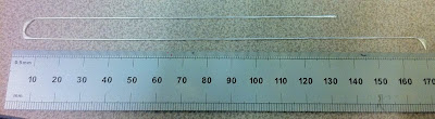
Above is the phase diagram for the system. My first alloy was 69.9% tin 29.2% bismuth and 0.9% indium (wt. %). Per kilogram the cost of the material was about £90 and I converted it to filament using the same casting trick. However this was a one off order so I anticipate it being substantially cheaper in quantity. The phase diagram predicted that this alloy should be about 80% solid when it begins to melt at about 130 deg C, and be fully molten by just under 200 deg.
The above was printed directly onto glass. I decided at the start of all this that if we are to produce useful circuits,we need to have sufficient control to build the track free form directly on top of PLA. Previously we needed channels to get any sort of the consistent track so this was already a big step forward. The rounding at the corner is due to the layer height being slightly off, which seems particularly critical when compared to plastics.
After the initial success, this is where the onslaught of problems began. Something I did not anticipate was that the alloy began to dissolve the brass nozzle due to solubility effects after very little use. In practice this meant that my extrusion parameters were constantly varying until the nozzle completely disappeared (this happened within about 15 meters of 3mm filament) . I also attempted an aluminium nozzle with the same result.
 At this point we were a bit stumped. Adrian suggested trying to make an all PTFE extruder (at least as far as the alloy was concerned). After several iterations the best solution was machining a PTFE liner with a built in nozzle. This was then surrounded by the usual brass heater etc like our hybrid extruders. Whilst I accepted this was not a long term solution, I thought that if we could get it to work in steady state conditions we could learn more about the process.
As it turns out with extended use the alloy was so viscous the alloy physically ripped the PTFE liner that serves perfectly well in our plastic extruders. Further it was apparent a black oxide was forming at the entrance to the nozzle. After a few hours use this ended up in a complete extruder failure.
After this failure it was fairly apparent that my initial alloy was far too aggressive. I therefore scaled it back to something that would operate at lower temperature (reducing oxidation times) whilst also having a lower viscosity to put less stress on the PTFE liner.
I guessed that a 50% liquid/solid ratio when the alloy begins to melt would be sufficient, and this turned out to be a composition of 57.5%Sn, 41.3%Bi, 1.2% In, again beginning to melt at 130deg but finishing by about 170. This proved much more reliable and with much less oxidation. It allowed me to produce the results below printed directly onto glass (it was flat before I peeled it off). The second image is particularly interesting as its three layers of track on top of one another, which would be required for tracks connected in parallel. I've also gotten similar results printing directly onto a PLA substrate, in this case it stuck fairly well but could be removed with a bit of force.


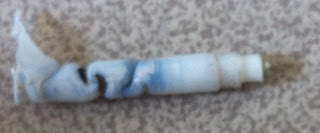
Whilst I've achieved fairly decent results with this setup, the transient performance was unsurprisingly poor given the insulating nature of the PTFE and the large melt zone I needed to get it to work. I therefore went back to solving the underlying problem of the alloy dissolving the nozzle. I've had ago at anodising an aluminium nozzle which is fairly easy, it just requires about 200 Vdc and the appropriate electrolyte. At the moment the nozzle design is still varying a bit, but I've taken pictures under a microscope both after anodising (first pic) and after extruding about 10m of 2mm filament. As far as I can tell there hasn't been any substantial wear.


After about 10 different extruder iterations (most I haven't mentioned here) It appears that the dissolving issue has therefore been solved. I haven't quite finished calibrating this extruder, but the latest results are below. Naturally its our logo, the track size is about 0.7mm in diameter. Given this was fairly successful I also tried doing it with infill, unfortunately it overheated as the filament didn't have chance to cool but I still think its quite successful. I need to try repeating this with cooling from a fan. I would have continued this build further but I can only make lengths of filament about 30cm long and changing them mid print is quite tricky,


Labels: Printing Conductors
Tuesday, June 21, 2011
Reprap at the NextGen Science Fair 2011 in San Francisco
After many misgivings about the direction of the event {it was the Cable TV channel TasteTV's first such event}, the NextGen Science Fair 2011 came off very well. The number of exhibitors was quite small, and the entry fee was substantial at $25. I expected a few hundred people at most. In fact, I think we got many times that. We had a thick crowd around the Reprap table virtually all day long.
I brought my Rapman and my nearly complete Sampo and Brook Drumm, who set up the RepRap/MakerBot Builders in Northern California, showed up with his Makerbot Cupcake and his nearly complete Mendel. He's used his cupcake to make Mendel parts sets for everybody in his group since January of this year. Brook has become an accomplished Reprapper in a very short amount of time..
Here you can see Brook Drumm {left} of the RepRap/MakerBot Builders in Northern California talking about his Průša Mendel.

You can see from left to right, a Makerbot Cupcake {to the left of Brook}, a Průša Mendel just below his hands, the nascent Sampo printer and a Rapman 3.0 at the far right.
Brook and his daughter/assistant Sydney with their Makerbot Cupcake in printing Mendel parts.

Brook Drumm's Průša Mendel made from parts printed by a his Makerbot Cupcake.

A Darwin-derivative Rapman 3.0 monitored by Adriaan Higgs printing a y-axis drive belt gripper for the next generation Darwin-derivative Sampo printer just to the right.

Adriaan demonstrating the technology differences between the Rapman and the Sampo Darwin-derivative printers.

Showing the familiar Reprap banner at NextGen Science Fair 2011.

Labels: darwin, NextGen Science Fair, Průša Mendel, RapMan, reprap, Sampo
Wednesday, June 15, 2011
A "string wars" approach to the y-axis
In which your narrator applies a cabling approach to controlling the y-axis of the Darwin-derivative Sampo printer.

Do you want to read more?

Do you want to read more?
Sunday, June 12, 2011
Getting Rid of Mendel's Nuts
I’ve been working on something for a bit, and the results are starting to surface. I made a rash promise in the #reprap IRC on freenode.net to put up a teaser on Sunday, so here it is. It’s a RepRap variant with no fasteners in the frame, using sockets to accept the (in my case) 9.4mm aluminium tubing struts. You can assemble it with my favourite tool - the mallet! So far the only screws are those needed to hold the motors, belts and extruder guts in place (though as the extruder isn’t built yet so that ain’t saying much). Holes are provided for adding glue to the structure, and for the particularly fastidious they can be drilled and tapped as well. I’ve even made the glue cavity the shape of an M3 nut so you can in theory make strategic joints releasable to aid portability if you really do like your nuts..

Um, ignore the basket of fresh clothes. Suz thinks the workshop is some kind of laundry. Even keeps the washing machine there.
The shedding of M8 rod has other advantages besides removing the need for many fasteners and making the whole thing lighter. A good one is that the frame struts can now be smooth enough to run the axis skids on - running a skid on M8 thread is a teensy bit like sliding down a grater. This removes the need for some lengths, lightening the structure still more. Make it from hunting arrow tubing and you’d be going featherweight. Use bamboo and go eco. Many options.
The design of the new Z axis hinges on the use of a Sarrus Linkage, ahha, ahha. I’m hoping something cunning can be achieved with a DC servo and string, but until then a NEMA17 and a piece of M3 threaded rod will do. No there is not a lot of Z travel in my quick bodge (unless you count the slack when it wobbles up and down at present), but there is enough to get on with. The Sarrus is actually a great fit mechanically for the Mendel-style frame, because the Sarrus gets narrower as it gets taller - just like the Mendel’s triangular profile.
The X axis is right at the top, and a one-piece extruder/carriage slides back and forth across the top two runners. I’m still coding the brackets and idler for that. Yes, coding. The whole thing is parametric. The Y axis is more firmly in reality. This is a cunning sled that pulls itself together with a couple of rubber bands. This causes the sloping faces of the runners to move up the side of the rod as they travel, until they hit the top. This kills wobble automagically and is remarkably tolerant of mis-aligned Y bars. It’ll even work upside-down! The proper Y motor bracket is still being designed, so for mechanical testing I used fancy stuff called string...
The vertexes are going to change a bit from the picture. They’ll have to be a bit wider to accommodate the X carriage, higher so the Z axis does not scrape it’s butt on the ground, and braced for extra stability. None of it needs support for printing.
That’s enough for now. I’ll get back to it. More news & photos as I sort releasable stuff out. Just remember that I’m going to be releasing this as soon as it is vaguely usable, and as yet it isn’t!
Around the RepRap Community
So much has happened in the RepRap community since my last update. Hackerspaces and building RepRap can really suck the time out of you. Because there is so many awesome things going on in the community that are not documented in the RepRap wiki, this post is going to include lots of non wiki related material.

Makergear Mosaic
Anyone who knows me knows I have a soft spot for RP parts 3d printers, but the Mosaic is something special. This is the 1st RepStrap kit avialable with linear motion rails on the X and Y axis and a multistart teflon coated ACME leadscrew with 2 linear rods on the Z. It only takes a cursory glance to tell the design is inspired by the Up! by PP3DP but with all the things to not like about an Up! fixed:
UP! closed source / Mosaic will be open source after 1st shipment
Up! $2900 plus $150+ Shipping / Mosaic $999 + less than $50 shipping
Up! Proprietary Electronics / Mosaic Ramps Electronics (No electrical part costs more than $30 to replace)
As you can tell, I am a bit stoked on the Mosaic, can't wait to see more pictures of the stuff that comes off the machine.

Pronterface
Kliment, another one of our devs who seems to not sleep has released a really nice new printer interface for RepRap. This interface is designed from the start to work with SD card on both Ramps and Sanguinololu. The great thing is it defaults to 115200 connection speed so your not having to change the connection speed every time you turn on your machine.
Sprinter Firmware
Sprinter is a new generation of firmware for reprap. This is the 1st firmware that has native support for SD card, and extreme acceleration. This firmware can run a printer at up to 300mm/s, which really changes the quality of a print. Sprinter has been tested and works on Gen6, Ramps, and Sanguinololu.
")
Mendelparts Orca
Mendel Parts is transitioning over to the Orca from their Sells Mendel design. Orca is Mendelpart's 1st inhouse designed RepRap, and maintains the 200x200 traditional build area for a RepRap. At $816 it's a really good deal on a kit.

EMaker Huxley
I love cheap, I love RP parts, and I am fascinated by the bowden extruder with 1.75 filament. So here is something special. This is a $475 full kit for a RepRap with 140x140x110mm build area, SD card support, and everything included for less that $500
Less than $500 for a full RepRap, That's right folks it took less than 1 year (Oct 2010 to now) for the cheapest RepRap kit to go from $1000 to sub $500. No one knows how long term this price is considering it's from a reputable dealer though a kickstarter style offering, but he got the money for the project and he is saying around August is the delivery time.
Huza for a $500 RepRap kit!

Assembled MakerBot
For as long as I have been around this community I have seen people wanting a preassembled RepRap/RepStrap. Well at long last it is here. Makerbot is now offering to preassemble their $1300 Makerbot kit for an additional $1200 fee.
No news yet on how they are going to handle people who don't know how to fix their machines, but this should make for fun times in the Makerbot and RepRap IRC when people don't know how to take apart their hot end to clean out a jam.
I know I missed a lot of stuff in the post, the RepRap devs have been busy these past few months, I will attempt to get back to posting on a regular schedule again.. Thank you all for your work and have fun!
Makergear Mosaic
Anyone who knows me knows I have a soft spot for RP parts 3d printers, but the Mosaic is something special. This is the 1st RepStrap kit avialable with linear motion rails on the X and Y axis and a multistart teflon coated ACME leadscrew with 2 linear rods on the Z. It only takes a cursory glance to tell the design is inspired by the Up! by PP3DP but with all the things to not like about an Up! fixed:
UP! closed source / Mosaic will be open source after 1st shipment
Up! $2900 plus $150+ Shipping / Mosaic $999 + less than $50 shipping
Up! Proprietary Electronics / Mosaic Ramps Electronics (No electrical part costs more than $30 to replace)
As you can tell, I am a bit stoked on the Mosaic, can't wait to see more pictures of the stuff that comes off the machine.
Pronterface
Kliment, another one of our devs who seems to not sleep has released a really nice new printer interface for RepRap. This interface is designed from the start to work with SD card on both Ramps and Sanguinololu. The great thing is it defaults to 115200 connection speed so your not having to change the connection speed every time you turn on your machine.
Sprinter Firmware
Sprinter is a new generation of firmware for reprap. This is the 1st firmware that has native support for SD card, and extreme acceleration. This firmware can run a printer at up to 300mm/s, which really changes the quality of a print. Sprinter has been tested and works on Gen6, Ramps, and Sanguinololu.
Mendelparts Orca
Mendel Parts is transitioning over to the Orca from their Sells Mendel design. Orca is Mendelpart's 1st inhouse designed RepRap, and maintains the 200x200 traditional build area for a RepRap. At $816 it's a really good deal on a kit.
EMaker Huxley
I love cheap, I love RP parts, and I am fascinated by the bowden extruder with 1.75 filament. So here is something special. This is a $475 full kit for a RepRap with 140x140x110mm build area, SD card support, and everything included for less that $500
Less than $500 for a full RepRap, That's right folks it took less than 1 year (Oct 2010 to now) for the cheapest RepRap kit to go from $1000 to sub $500. No one knows how long term this price is considering it's from a reputable dealer though a kickstarter style offering, but he got the money for the project and he is saying around August is the delivery time.
Huza for a $500 RepRap kit!
Assembled MakerBot
For as long as I have been around this community I have seen people wanting a preassembled RepRap/RepStrap. Well at long last it is here. Makerbot is now offering to preassemble their $1300 Makerbot kit for an additional $1200 fee.
No news yet on how they are going to handle people who don't know how to fix their machines, but this should make for fun times in the Makerbot and RepRap IRC when people don't know how to take apart their hot end to clean out a jam.
I know I missed a lot of stuff in the post, the RepRap devs have been busy these past few months, I will attempt to get back to posting on a regular schedule again.. Thank you all for your work and have fun!
Saturday, June 11, 2011
Founder's Forum

My daughter, Sally, and I took one of our RepRaps to The Founder's Forum 2011, where I also gave a talk. The event is organized by Brent Hoberman, and so many thanks to him for the invitation. I wouldn't normally name drop, but you can get some idea of the event by the celeb end of the guest list (Stephen Fry, The Duke of York, Davina McCall...) and that fact that there literally were more helicopters parked outside than Ferraris.
We shuffled our Ford Fiesta (complete with bat droppings on the bonnet from the roost in our garage) between a couple of Tesla Roadsters, lugged the RepRap machine to centre stage, and set it running.
Given the above, you won't be surprised that there were some top-end journos present too, so we got some good publicity out of the whole thing. Follow the links:
Rory Cellan-Jones and Robert Peston of the BBC (Of RepRap, Peston tweeted, "Real life better than Dr Who."), and
Ben Rooney of the Wall Street Journal.
Wednesday, June 08, 2011
Prusa Felt branch and ThingDOC
So, if you are wondering whats new in Prusa printer development, I'll answer some of your questions today. And maybe even bust some myths ;-) First I want to show you results!
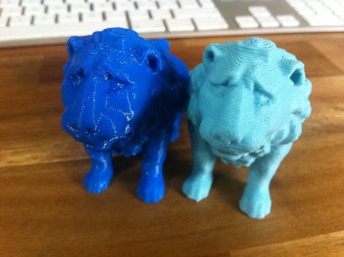
(Darker blue is print from Dimmension uPrint, Lighter blue is print from Prusa with felt bushings)
For more pictures and info follow the link on the end of this post.
New bushing look

In the same printed object you can use:
- felt (100 bushings for $5 if you use best felt)
- brass tube (80 bushings for $9)
- pla bushings (one prints in about 30seconds :-D)
- igus bushings (as Shapercube use, it's pretty expensive because of matching rods)
- sku bushings (steel with teflon inside, expensive because of rods $50 per full set incl. rods)
All of this stuff remains snap in! So you can remove your carriage without disassembling half of printer.
During the big demand I will incorporate the possibility to use linear bearings too, but it will be few days after this release. And it's not going to be the main stuff. Simply because it's not better and sourcing is harder and pricier.
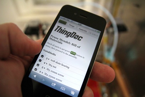
ETA to merging it to master branch is about two weeks. Catching last bugs out. And also, from this point, every commit will have its own ThingDOC documentation, which is under huge development during moving documentation to the files!
ThingDOC is now Ready for its prime time!
For more informations, images and links, visit original post.
Jo Prusa
(Darker blue is print from Dimmension uPrint, Lighter blue is print from Prusa with felt bushings)
For more pictures and info follow the link on the end of this post.
New bushing look

In the same printed object you can use:
- felt (100 bushings for $5 if you use best felt)
- brass tube (80 bushings for $9)
- pla bushings (one prints in about 30seconds :-D)
- igus bushings (as Shapercube use, it's pretty expensive because of matching rods)
- sku bushings (steel with teflon inside, expensive because of rods $50 per full set incl. rods)
All of this stuff remains snap in! So you can remove your carriage without disassembling half of printer.
During the big demand I will incorporate the possibility to use linear bearings too, but it will be few days after this release. And it's not going to be the main stuff. Simply because it's not better and sourcing is harder and pricier.
ETA to merging it to master branch is about two weeks. Catching last bugs out. And also, from this point, every commit will have its own ThingDOC documentation, which is under huge development during moving documentation to the files!
ThingDOC is now Ready for its prime time!
For more informations, images and links, visit original post.
Jo Prusa
Sunday, June 05, 2011
Unreasonable Rocket's 3d Printed Rocket Engine Takes Flight!
My two passions are Rocketry and 3d Printing. Paul Breed has combined the 2 in his test flight of a 3d printed stainless steel rocket engine.
To my knowledge this is the 1st successfully flown liquid fueled 3d printed rocket engine.
Paul Breed has a wonderful blog over at http://unreasonablerocket.blogspot.com/, you should really check it out, a lot of his issues with his 3d printed Rocket engine dovetail with issues we will run into as we use our parts for higher temp/pressure applications.
Wednesday, June 01, 2011
The end of the String Wars
It appears that the cabling approach to z-axis positioning that Ed Sells tried and abandoned on ARNIE, the precursor to Darwin, in 2006 can be made to work. Ed was trying to move the cable with something like a friction wheel, if I recall correctly and couldn't get sufficient friction between the wheel and the cable for reliable movement. I solved that by using a lead screw and thrust collar attached to the turnbuckle in the cabling loop.

Hopefully the use of a single lead screw will go some ways towards curing the slight periodic unevenness in print layering caused by wobbling in the four leadscrews used in the Darwin and Darwin-derivative Rapman printers. Kaizen is a very powerful approach to technological advancement.
![]()