Thursday, October 30, 2008
Puddle to the Metal

I don't normally blog mere links, but with progress being so rapid recently we'll revivify the metal-inlay extruder very soon so we can do electricity. So here are some materials that we could use for that:
http://www.princeaugust.ie/alloys/
Note that one would also be able to cast just about all of these in a silicone mould.
Labels: multiple materials
Wednesday, October 29, 2008
Exchangeable Lasercut Extruder
 I've been working on the design of the Ponoko lasercut extruder. I've managed to make it fit better into the extruder socket and even made the "handle" on the extruder clamp variable in width for maximum grip by putting a split in it.
By tightening or loosening the M5 locknut on the screw that goes through the "handle" (roughly in the centre of the picture) you can pull its two halves, expanding or shrinking the handle's thickness.
The whole thing is compatible with the Darwin exchangeable extruder, and in fact seems more rigid. If there's an interest in making the extruder available as a kit on its own, let me know and I'll do so.
In the photo, the red pieces are made from 3mm acrylic, the gears from 8mm and the rest from 4.5 mm. I've also made parts to hold an opto sensor in place which I've not fitted and a 1:1 gear set that I've yet to try out. Busy writing assembly instructions ...
Vik :v)
Labels: extruder, lasercut, ponoko, reprap
Sunday, October 26, 2008
New Board: LCD Controller v1.0
 This is a fun board that has some really cool potential. It was primarily designed by Bruce Wattendorf who did the heavy lifting on finding the right chip, prototyping it, and figuring out all the technical details. I hacked on it a bit to get it ready for production with proper silkscreen and such.
The heart of the board is an MCP23S17 chip made by Microchip. This chip is really cool: it is a 16-bit port expander that you can communicate with via i2c. They also make a nearly-identical one you can talk to via SPI. Our board supports both of those chips. We chose to go with i2c, because it is fewer wires and slightly easier to interface.
The board is designed for the upcoming Sanguino Motherboard which will have matching i2c headers, although you could talk to it with anything that is an i2c master. We only needed 11 pins for the LCD screen, so we've provided the remaining 5 pins as headers for your hacking pleasure. We're planning on making a breakout board with some buttons, or perhaps LEDs. You could easily make your own as well with perfboard.
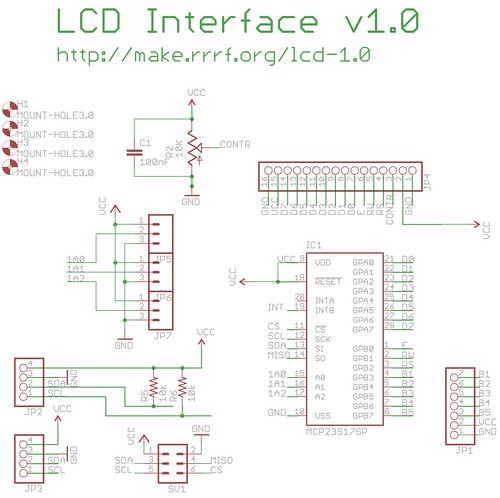
If you'd like to download the design, its available on SourceForge. We just sent it to the fab today, so it will be at least 10 days until we have prototypes back. Boards and kits will be up on the RRRF store ASAP.
Finally, big thanks to Bruce for his help and contributions. I'd also like to take the opportuntity to point out that this type of collaboration is what the RRRF is for: to help researchers and contributors to the RepRap project see their ideas reach fruition. The RRRF funded the prototypes for this design and might fund yours as well. If you have a design for something that fits with the goals of the RepRap project, please email me at hoeken at rrrf dot org. We don't have funding, so all the money for research comes from sales at the RRRF store if you'd like to support us.
Oh, and here's a video from Bruce:
RepRap I2C LCD test board from Bruce Wattendorf on Vimeo.
New code first build
This improvement was confirmed experimentally and in production by Nophead's Hydraraptor work, and by Zach's ReplicatorG G-Code RepRap-driving program.

Here is the first build out of the standard RepRap Java host software updated as in the post below. It's the RepRap coat hook. I computed the slices and saved them to a GCode file (this took about 12 minutes). Then I replayed the file (this took about an hour and a half). This was on my home RepRap, driven by a Sanguino running the Sanguino GCode firmware extruding ABS at 240oC.
Above is the coat hook unretouced just after the build finished.

And here is it after brushing the hair off. The quality is almost as good as the superb results that Nophead gets, at which I am well-chuffed as I haven't finished tweaking the parameters yet.
One tiny bug became aparent: the Java hangs writing the GCodes to a file if the RepRap machine isn't plugged into the computer's USB port, even though nothing is going to the RepRap machine at that stage. Now I'm off to hunt that one down; I suspect I may have been too clever adjusting thread priorities...
Tomorrow, Ed and I will get together in the lab at Bath to make sure this all works with the Arduino (which we have on the lab machine) as well as the Sanguino.
Labels: g-code file, host software, java, Sanguino
Saturday, October 25, 2008
Multimode Host Software

I have been working on the Java RepRap host software. The latest version (https://reprap.svn.sourceforge.net/svnroot/reprap/trunk/reprap) allows you to:
- Load STL files and print them on a SNAP RepRap (PIC or Arduino).
- Load STL files and print them on a GCode RepRap (Arduino or Sanguino).
- Load STL files and print them as GCodes to a file.
- Load a GCode file and print it on a GCode RepRap (Arduino or Sanguino).
The transmission using GCodes is buffered through a separate thread which makes it pretty smooth. This works particularly nicely with GCodes stored in a file (as with Zach's ReplicatorG), and gives good-quality builds. As soon as I've got something more interesting than a cube, I'll post it.
I've had to change a few preferences values - see http://www.reprap.org/bin/view/Main/RepRapSoftwarePreferencesDocumentation.
Finally, you'll see that there is a greyed-out button for "Load RFO". This is the format that Zach proposed along with the Fab@Home guys for multiple-material builds (see http://reprap.org/bin/view/Main/MultipleMaterialsFiles). Watch this space...
Labels: g-code file, host software, java, Sanguino
Sunday, October 19, 2008
Lasercut RepRap Available in Australasia & US

At long last, I have got the lasercut RepRap kit online, available now from Ponoko here. Cost of the lasercut components is approximately US$380 plus shipping, and it is compatible with the electronics kits and motors sold by the RepRap Research Foundation. As you can see from the photo on the right of the X axis assembly, it uses ball-chain instead of 2.5mm timing belt. What you can't see is that it also has an option for using lasercut bearing races instead of skater bearings. That worked really quite well.
I've bearly started the instructions here. The instructions on the BitsFromBytes page are generally applicable and will fill most of the gaps, though the Ponoko variant does use more laminated parts to avoid having to use routing. I recommend using all clear acrylic as it is much easier to see through the parts and see what you're doing!
I have also started acquiring Australiasian suppliers for PTFE rod, PLA filament, fine nichrome wire and stepper motors with a view to making a complete electronics kit available from local sources.
Hopefully we can redress the balance and get a few more RepRaps going in the Southern hemisphere!
Vik :v)
Labels: ponoko, reprap, repstrap
Friday, October 17, 2008
ReplicatorG 0002 Release
 Today has been a busy day... I'm also releasing ReplicatorG 0002. If you're not familiar with this software, its a generic GCode host software designed for use with RepRap machines. You feed it a GCode file, it parses it and then uses a driver based system to control a RepRap machine. Its simple, modular, and expandable. Its based on the Processing/Arduino codebase so it has a nice, friendly GUI system. Its also cross-platform straight out of the box. The installation process is pretty straightforward: download it and run it! You might have to install Java if you dont already have it.
Anyway, here is the changelog:
* add units to simulation window
* add proper bounds to simulation window
* add warmup/cooldown to machine config
* add simple exerciser / status window
* add color to simulation window
* add up/down arrows to simulation windows
* implement Peter Edworthy ideas on driver instantiation
* have simulation move to a proportional wait time
* fix build time estimation
* add estimate menu item
* add basic machine configuration stuff to XML (axes, resolution, extruders, toolheads, clamps, etc.)
* move to a controller/model/driver system.
* Add an extruder section (temp, start/stop extruder, extruder direction, extruder speed)
* added text boxes to control/display feedrate data
* fix shutdown of driver
* fix windows icons
You can download ReplicatorG from google code, or head over to the Replicat.org website to learn more about the software.
Sanguino Software v1.3 Release
I've tested and fixed the following libraries:
* LiquidCrystal - for controlling LCD displays
* Servo - for controlling servo motors
I've fixed, but not tested the following libraries (need circuits to test on):
* Wire - for talking i2c to various things
* Ethernet - for doing ethernet communication
Anyway, you can download it from SourceForge or check out the Sanguino homepage.
Wednesday, October 15, 2008
Yes - it's a square...

...but a square made by a Sanguino-controlled RepRap...

...running the G-code interpreter driven directly by the standard Java host software.
The control panel can now send G codes if they're switched on too, so you can control a G-code RepRap interactively.
I want to get to the point where we can drive both the Arduino and Sanguino running either the SNAP protocol or G-code all using the same program.
The next step is to reconfigure the Sanguino so it uses the latest pinouts decided by Zach to give the maximum electronic versatility.
Labels: host software, sanguino g-codes
Sunday, October 12, 2008
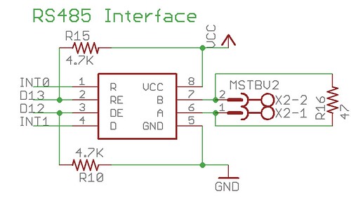
RS485 Circuit = Success
 Recently, I've been working on the 'Generation 3' electronics based on the Sanguino / atmega644p chip. This new generation of electronics sets out to solve many different problems with the current electronics: modularity, simplicity of wiring, microprocessor power, as well as adding many new features: sd card support, lcd support, interface support, and much more. This next generation of electronics is a large topic, which I will cover in future blog posts, but for now I'd like to focus on one particular feature: the data bus for the modular extruder system.
If you remember back to the days of the Generation 1, PIC based electonics we had a token ring system where each part of the system had its own microcontroller and was connected via TTL serial. This system suffered from many flaws, including noise in the serial lines connecting the various microprocessors.
The Generation 2, Arduino based electronics fixed this by swinging to the opposite end of the pendulum: all the electronics are controlled by a single microprocessor and no serial data connections are required (except to the computer). The main disadvantage to this is that the Arduino is pretty underpowered to drive a complex system such as a RepRap machine. We managed to do it, but we had to take quite a few shortcuts. This basically means we're also pretty limited in the things we could achieve.
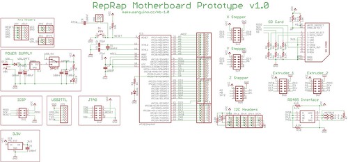 The Generation 3, Sanguino based electronics will swing back towards the middle, using a 'best of both worlds' approach. It uses a more capable microprocessor which solves the memory and pin problems. However, even with more pins its is still tricky to drive more than 2 extruders, or one extruder and an LCD screen / button interface. Thus, we need a modular system to allow expandability.
This long winded intro brings me to the subject of this post: RS485. This is a serial communications specification that uses differential signaling. The awesome thing about this is that it offers many cool things, one of which is improved noise immunity. As the wire contains the same signal twice (once normal, once inverted) When it gets to the other end, and the inverted signal is transformed into a non-inverted signal and combined with the original signal. Any electrical noise that was picked up is then cancelled out due to wave mechanics. Cool, huh?
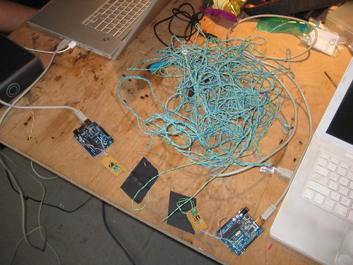
 I'm not an electrical engineer, so this stuff is all pretty new to me. Fortunately, we have many smart people participating in the RepRap project with experience in many different areas. One of those people is Nophead, who you may remember from his excellent HydraRaptor machine. He might deny it, but he's an electrical genius and he gave me a chip number and a circuit for doing RS485 communications. Today I built and assembled it.
In the picture you'll see the eventual setup I had going. I wired up two RS485 circuits to two Arduinos, and wrote a quick sketch to get them talking. The connection was a very long long, unshielded, twisted pair cable from an old ethernet cable. I hooked all these up and started them communicating. It worked great! I also did a test to try and inject some noise into the system by operating a powertool right next to the wires. It was very unscientific, but the RS485 connection didn't skip a beat.
There was one problem that I ran into, which was easily fixed. The Arduino only has one hardware serial port, which was being shared by the RS485 chip as well as the FTDI usb -> serial converter chip that is on all Arduinos. The problem was that when uploading a new sketch to the arduino, the RS485 would also be sending and receiving data which would seriously mess with the uploading process. Luckily, the RS485 chip has both a transmit enable and a receive enable pin. I used the appropriate pullup/pulldown resistors to default these both to off so that when the Arduino was reset for the upload process, the RS485 was disabled. This means that I had to wire up an additional two pins on the arduino to control the RS485 receive/transmit status. This is not a big deal because using RS485 frees up a lot more pins than it uses, so there will be plenty of pins available.
Anyway, today was a good day of hacking. Hopefully later this week I'll be able to wire up the SD card and run it through its paces. Luckily for me, there are schematics and code already written for the Arduino all over the internet, which means that it will be fairly trivial to wire it up and getting it working on the Sanguino.
Wednesday, October 08, 2008
New Board: Arduino Breakout Shield v1.4
 I sent a new board off to the fab today. This one is an incremental improvement on the super useful Arduino Breakout Shield v1.3. Here are the major things that have changed:
* 4th row of GND / 5V terminals re-arranged to avoid shorting out on USB connector
* added 2nd row of arduino-spaced headers to allow shield stacking
* re-arranged reset / power led
* made board square
* added mounting holes!
* tweaked silkscreen
I think with these tweaks, this board will be pretty awesome. I'm excited to get them back.
Source files posted to SourceForge, and are also available in subversion as usual. Documentation will be posted to the wiki as soon as i have boards in hand to document.
Sunday, October 05, 2008
RepStrap In Chains
 On the left we have the "Shiny" lasercut RepRap/RepStrap, completely fitted out with ball-chain drive and it all feels just fine. No rattly movement, though some of the screw heads are catching in the Y motor coupling and motor mount. I'll have to add a few washers or shorten the motor-mount/frame coupling bolts.
The Z drive was tested by connecting it to Phoenix and using the Arduino electronics on there (you can see the Y stepper controller on Phoenix's frame lower far left). The Y and X axes were tested by engaging my electric screwdriver in the adjustment slot at the rear of the motors, and whizzing it back & forth. Not a full-on electrical test, but the mechanics should do the job.
I have also properly fitted the NEMA17 motor to the X axis on the now fully-assembled Phoenix, and that checks out okay - and I printed an ABS cat. All in all a very busy weekend.
Vik :v)
Labels: ball chain, reprap, shiny, stepper
Saturday, October 04, 2008
Building ABS on a lasercut/fabbed Darwin
 I've managed to put together one extruder from the bits of lasercut prototypes Ponko have been cutting for me. It slotted straight in to the Darwin head exchange mechanism, but was a bit loose. I've got a better extruder base already being cut by Ponoko so I was expecting that and simply wrapped it with tape. The extruder motor is a little far away, so a temporary heave-to has been executed with a cable tie. Sorry, ugly. Is also fixed already.
I've loaded it with ABS and am now printing components with it, as you can see in the photo, as well as a classic Mighty RepRap Power Ring. I've fitted the ABS extruder to a Darwin to try my hand at testing out ABS, Imagin Plastics were kind enough to give me a 50m sample of 3mm ABS natural. Looks good, and I should be able to get it for under NZ$20 per 100 metre coil.
I've found ABS to be generally the hardest plastic to work with. It needs high temperatures, high pressures, and isn't that keen to laminate. You have to work in thin layers to keep lamination, which slows me down. It does score on accuracy and tidiness, however, as the paste-like exudate stops fairly rapidly even without a valved nozzle.
You need to have your nozzle mounted very rigidly, because ABS is not that easy for the hot nozzle to plough through if there are any rough bits sticking up from the surface. This is another reason I found to use thin layers and go slowly.
Getting ABS to stay down on the bed is hard too, but by accident I made one of those handy discoveries: With an eye-dropper, put a few drops of acetone (methyethylketone for the new-fangled) on a wooden extruder bed where the printing will take place. This hugely improves the adhesion to the bed, BUT IS VERY FLAMMABLE! Just bear it in mind, and keep the big can of acetone well away with the lid on just in case, eh? (PS What pen do you label little acetone bottles with? It all gets dissolved off when I spill it!)
Things bode well for an alpha release of the Ponoko lasercut components kit. I'm getting excited about that, and it should tie in nicely with the imminent arrival of Zach's new shipment of extruder motors on the RRRF site.
Oh, the curly-white wave flowing over the top of the big washer holding the extruder barrel is an ABS leak between the PTFE insulator rod and the top of the brass M6 extruder barrel. I hadn't anticipated the need to seal it, but the ABS starts pressurizing some way up the PTFE rod and squooshes out the gaps in an organic way. I'll seal the gap with PTFE tape when I install the latest extruder clamp assembly off the pending prototype lasercut run.
Vik :v)
Labels: ABS, lasercut, ponoko, reprap
Friday, October 03, 2008
New Board: Stepper Motor Driver v1.2
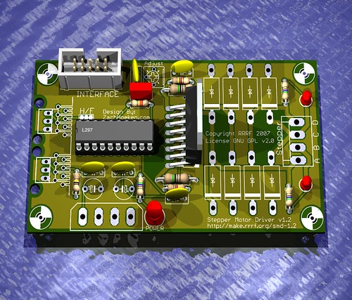 I sent a new board off to production earlier this week, the Stepper Motor Driver v1.2. This board is a minor upgrade from the previous Stepper Motor Driver v1.1 board. It still uses the same L297/L298 chipset (all through-hole!) but I've modified it a bit:
* added 10-pin IDC header for interface
* simplified unique component count
* removed a couple unnecessary components
* re-laid out the board to route better
* added RJ-45 footprints w/ optional .100" header
I've also been working on the Generation 3 electronics for a while now. One of the things I'm aiming to achieve is making everything a bit more friendly to assemble. One of those things is the switch to using IDC connectors where possible. These things are super easy to make, polarized, and fairly cheap. I'll be coming out with a 'Sanguino Motherboard' soon which will have complementary IDC headers. Wiring up your RepRap will be *much* simpler with these new electronics.
Of course, you can easily just have an IDC connector on one end and route the individual wires to where you want.
Files posted to SourceForge or available in SUbversion as always.
Wahooo!!
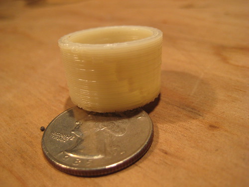 Well, I finally did it: I've printed my first minimug. This may come as a surprise, but the Director of the RepRap Research Foundation has never printed anything, UNTIL NOW! (Hey, I never said I was *good* at this stuff, just that I love working with it.)
I'm really excited about how this build turned out. Here's my current setup:
3-axis system: Darwin
Extruder: Lasercut Extruder (variant on BitsFromBytes.com design)
Electronics: Arduino + rotary encoder
Firmware: GCode Interpreter
Slice/Dice: Skeinforge
Control Software: ReplicatorG
I'd like to take this opportunity to reflect on the past few years of work (wow!) and say that I've thoroughly enjoyed working on the project and I look forward to working on it even harder in the coming years.
When I first started working on RepRap, I was a wild-eyed college student with dreams of 3D printers and being able to whip together a 3D printer in a few days and start changing the world.
Of course a few days turned into weeks, which turned into months, which turned into years. I've learned a *ton* along the way though and have had my share of mis-steps as well. I've come from basically zero understanding about electronics, firmware, microcontrollers, extruders, and cartesian robots to a point where I am reasonably comfortable with all of those technologies and am now active in developing and hacking on the next generation designs.
We've come a long way as a project from the early days, and luckily things have only changed for the better. For example, when I first got started, the first thing I did was build the electronics. Except there were no manufactured boards. Adrian had but up a little how-to on the website about how to etch your own boards. I decided that this was way too hard for myself (and by extension, your average person) so I decided that I would get them manufactured. Thus the RepRap Research Foundation was born. Since then, nearly every single part you need to build a RepRap is now available from either the RepRap Research Foundation, or BitsFromBytes.
I'm not sure where I'm going with this, but I'm excited about the future of this project. Now that I have these physical objects in front of me that my machine produced, it feels so much more real. No longer is the printer this magical dream that I've been chasing for so long, but it is something that I have sitting in front of me. There are many things to be improved, and there are many things to be changed, but it works, and thats good enough for now.
For all those out there who are just following along, or are struggling with building your own machine: keep up the fight, and keep hacking on it. You'll have your machine working and when you do it will be beautiful.
Cheers,
Zach 'Hoeken' Smith
Wednesday, October 01, 2008
RepRap Builder's Wiki

Today we launch the RepRap Builder's Wiki. Here anyone can post any RepRap information that will be helpful to the RepRap community.
Don't be frightened to tidy, to re-organize, to correct and to clarify the work of others, but don't delete anything without good reason (good reasons are things like the post is offensive, is spam, or is scientifically incorrect).
By all means include lasting information that has previously appeared in the Main Blog, the Builder's Blog or the Forums - we want to systematize that in a chronologically-independent way on the Builder's Wiki. But please don't post questions (they belong on the Forums) or information that is transient. Indeed, if all you do is to take some nugget from one of those sources that you personally have found useful and post it on the new Wiki, you will be doing everyone else a great service.
Belts anyone?
In which your narrator makes a serendipitous discovery that may well impact replicating one of Darwin's critical parts while cleaning up Tommelise... read more
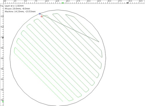
Testing the envelope

What you are looking at is a six-toothed involute profile sprocket gear cut on Tommelise 2.0. It has a pitch radius of 6 mm, a pressure angle of 20 degrees and with its involute profile surface defined by six planes. I cut it with a 1/16th inch cutter mounted in a flexible drive shaft on a standard Dremel hand tool mounted to Tommelise 2.0's positioning robot. It was cut in commercial 1/4th inch black, HDPE sheet. This sprocket is probably smaller than it needed to be.
I wanted, however, to test the envelopes of my Slice and Dice software, the cutter and the positioning accuracy of the Tommelise positioning robot. I could probably get eight teeth on a 6 mm pitch radius gear, but that would be right at the limits of my system.
It took me about two and one-half hours to cut it. Most of that time was spent worrying that I'd mar the piece. It should go quite a bit faster in future now that I have the parameters for working HDPE on this machine.
Labels: "gear", "involute profile", "Tommelise 2.0", milling, reprap
![]()