Monday, February 26, 2007
Paste extruder
I have been working in the background on a paste-extruder for RepRap that is as simple as I can make it. It's based on an idea of Zach's and Forrest's.
It's just passed its first test:
(Slightly surreally, the sound track consists of a musical biography on Radio 3; I was listening, and forgot to turn it off...)
It consists of a 500ml fizzy drink bottle containing a balloon that in turn contains the paste. You blow air into the bottle to pressurise it via a one-way valve, and the pressure then forces out the paste. It goes through a silicone rubber tube that is clamped off by a latching solenoid. Pulse the current one way and it turns on; pulse it the other and it turns off.
Of course I'd rather have used a condom than a balloon, just for max. cred., but they're the wrong size...
Here's a high-res still.

And here's a detail of the valve at A:

The paste being used here is Fine Surface Polyfilla, as proposed as a RepRap material by my student James Low last year. One small advantage that this stuff has is that leaks tend to seal themselves...
Printing with conventional solder
I gave the extruding solder thing another go before it got too late. This time I tried to lay down a track with a HDPE surface within a millimeter of the extruder head. Keep in mind that I was pumping the solder with one hand and moving the sherbet lid (my HDPE surface) with the other.
Still, I did get one reasonable trace (circled in red)

There was enough energy in the solder trace to etch it into the HDPE to a point where it is solidly attached to the plastic surface. When I say solidly, I mean that I can't peel it off with my fingernails.
If I get time in the morning I'm headed down to the hardware store to see if they have electrician's solder (as opposed to electronics solder) in a diameter something like 3 mm.
Printing circuitry in the low-rent district
I'm always inspired by Adrian's groundbreaking work. I guess I must see things with different eyes, though. I read his blog entry on working with low temperature eutectic alloys in the a little while ago. It seemed to me he'd gone to heroic lengths to make what was, for practical purposes, a piece of 3 mm solder. Mind, being Wood's metal it's solder that will melt in a hot cup of coffee, but it's solder all the same.
His saying that he's wanted a filament that he could run through a Mk 2 FDM extruder put me on the hunt, I guess.
You see, I know that my low thermal inertia 2 amp extruder barrel is hitting somewhere around 190-210 degrees C (374-410 degrees F). I keep several diameters of solder. In regular acid core lead I keep heavy (1.27 mm) and fine (0.9 mm). Recently, I've been experimenting with a RoHS (no lead) compliant acid core solder in a fine grade.
Knowing how hot my extruder barrel gets I began to wonder whether I could get it to melt in my extruder barrel. Problem was my extruder barrel is 3 mm while my solder is 1.27 mm. As well, if I got it wrong it would be likely that I would jam the barrel.
Then I got to thinking about the old 1 amp prototype extruder barrel that I'd built and tested back in late December and early January. Naah, it'd never get warm enough. On the other hand if it jammed I hadn't really lost anything.
So, one thing leading to another I cut off a couple of inches of the heavy grade Sn63/Pb37 solder and folded it into a plug and stuffed it in the test extruder barrel which I'd locked into my vice and fired it up. I had a short length of 3 mm HPP to use as a piston so I was good to go. The test extruder had a plug of either ABS or HPP in the end from the last time I used it, so after the barrel heated up I inserted the HPP filament and began to feed it into the cold end (~70-80 degrees C) of the extruder barrel with a pair of pliers so that I wouldn't risk burning myself however slightly.

After the plastic plug melted and began to clear as I fed the HPP filament into the extruder I began to see droplets of solder coming out with the HPP as you can see here.

After a few seconds of transition between plastic and solder the rest of the plug came out in a rush and fell into the HDPE sherbet container I'd thoughtfully placed under the extruder barrel to keep things off of the carpet. The HDPE surface that they hit was relatively rough and the acid core solder adhered to them slightly.
Here was what was important though. The specific heat of metals is, on average, about 10% of that of organic materials like plastic. What that means is that dropping small amounts of something like solder on a plastic surface usually doesn't melt the plastic surface significantly in spite of the fact that the molten solder is far hotter than the melting point of the plastic. The plastic simply absorbs the heat like a sponge and chills the solder instantly.
Here is a closeup of one of the solder splashes that I peeled off of the HDPE surface laid on the tempered glass xy working plane of Tommelise.

I got my micrometer out and measured it at a very consistent 0.1 mm in thickness. Basically, I had a very nice piece of tin-lead foil for my troubles.
I repeated the experiment with the RoHS solder.

It behaved very differently. It came out in tiny beads with the HPP and in a few cases coated or partially coated the HPP. The two long threads of solder shown here at the center and left of the pic are actually electrically conductive wires made of RoHS solder. RoHS is going to take some more thinking about.
I guess I'll have to head down to the hardware store and see if I can find some hard copper tubing that can seat 1.27 mm acid core solder. I wonder if I can talk Adrian into printing me up a Mk 2 parts kit that can handle 1.27 mm solder. It would be interesting to see if I could print an HDPE blank and then print the traces for a Tommelise microcontroller board in solder on it. :-D
Sunday, February 25, 2007
Low-melting-point alloys
We've talked for some time about using low-melting point alloys like Wood's metal (65oC) and Field's metal (40oC) in a RepRap write head to allow us to build electrical circuitry, and such a system is being planned for RepRap 2.0 "Mendel". We have also talked of trying them in exactly the same extrude head that we use for polymers, for which we'd need them in the form of a 3mm rod.
I've always thought that the problem with this might be that the (admittedly small) melt cavity inside the head would simply drain out the bottom uncontrollably.

But the other day my student who's working on this, Mike Samuel, had a brilliant idea: why not replace the cavity with a small heated button with a fine extrusion hole through it, then just touch the metal on the back when you want it to melt and extrude? The extrusion system already has a mechanism to back the rod off; this would remove it from the hot-spot and stop the flow.
The head would be like the above. The brass part would have a heating coil, like the ordinary extruder, and a thermistor to measure its temperature. The Wood's metal rod would be fed into the top by the existing transport mechanism that's used for the 3 mm polymer rod we use. And all this would use exactly the same electronics and software to drive it that we already have.
So I tried to make some 3 mm Wood's metal rod.
My first experiment was rubbish: I had a small crucible with a 3mm hole in the bottom heated by a soldering iron. The hole led through an insulating block with a 3 mm hole to a cooled section with another 3mm hole, where I thought the metal would solidify and be able to be pulled through - pulltrusion, as it's called. The whole thing locked up frozen solid, and nothing would move anywhere.
Then I looked at the silicone tubes I was using to carry the cooling water. Dang me if they weren't 3mm internal diameter. I put one on a funnel with a clothes-peg at the other end, heated them all in a beaker of boiling water, took them out and quickly hung them up, then poured in the Wood's metal:
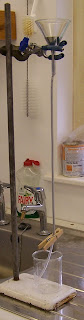
After it had cooled I just sliced away the silicone tube with a scalpel, which left a perfect shiny rod:

I measured it: 2.95 mm, all the way down :-))
Labels: Field's metal, RepRap electronics, Wood's metal
Thursday, February 22, 2007
Website Architecture Changes
Recently, we've made some changes to our setup on the web here. You may or may have not noticed, but we are now serving the vast majority of our stuff off the reprap.org domain. Recent changes include moving the forums, blogs, objects wiki, and mailing lists to reprap.org. Here are the new url's for those sites.
Forums - forums.reprap.org
Main Blog - blog.reprap.org
RepRappers Blog - builders.reprap.org
Objects Wiki - objects.reprap.org
Mailing Lists - reprap.org/mailman/listinfo
The forums are an especially new addition, and we hope you come in and chat with us. We've got alot of interesting topics going and you can even follow the developers mailing list as its mirrored there.
Labels: announcements, web site
Saturday, February 17, 2007
Extruding HDPE in the Mk 2.1
Just a note in passing. I've tweaked the Mk 2.1 for use with HDPE. It is currently extruding HDPE at a rate of just a shade over 4 mm/sec through a 0.5 mm extruder orifice with the extruder heater consuming 2 amps at 12.34v. The thread expands to about 0.75 mm after leaving the orifice.
I'm using the gearmotor in pseudostepping mode with an 80 msec power pulse followed by 160 msec pause.
It's important to remember with the Mk 2.1 that all of the spring loading on the filament must be put on the top two springs. Tightening the bottom two, something I intuitively do which is dead wrong, stops the flow.
I took a video of the extruder operating and put it on YouTube.
It's a little difficult to see the HDPE coming out of the Mk 2.1 in this YouTube video in that the molten plastic is transparent. About the height of the cardboard covered work surface, however, it cools off enough to go opaque which lets you see it being laid down.
One little note, that loop of cooling HDPE that you see is being laid down in mid-air. The filament leaned against the edge of the xy positioning table and then just started coiling up in the air about an inch above the level of the cardboard.
Labels: extruder, HDPE, Mk 2.1
Pressing Belt Gears
I've pressed 2 sets of belt gears for Darwin using my acrylic moulds. There are 4 sheets of acrylic with alignment holes (the 4 little bolts go in them). Sheets 1 & 4 have 8mm holes in the middle, sheets 2&3 45mm holes. A piece of belt goes around the hole in sheets 2&3 to put teeth on the edge, exactly as per the rig that Ed made. PVC food wrap stops the CAPA sticking to sheets 1 & 4. The trick is not to press too hard or you open up a gap where your belt joins into a loop.
They need a little trimming, but a sturdy pair of scissors does that just fine. Better than a craft knife.

Zach is kindly documenting the process here.
Vik :v)

They need a little trimming, but a sturdy pair of scissors does that just fine. Better than a craft knife.

Zach is kindly documenting the process here.
Vik :v)
Labels: capa belt gear polymorph darwin reprap
Sunday, February 11, 2007
CAPA Extruder Pushes Filament
One video of the completed CAPA extruder screw mechanism extruding a 3mm CAPA filament:
I'll add the clamp and hot nozzle later (waiting on some PTFE rod for that).
Vik :v)
I'll add the clamp and hot nozzle later (waiting on some PTFE rod for that).
Vik :v)
Labels: reprap extruder capa polycaprolactone filament
Friday, February 09, 2007
RepRapped extruder parts
I've finally managed to run off a complete set of parts for the screw section of the extruder - clamp still to come. The screw holder itself took me 6 goes to get right (at least we know the extruder can generate a lot of output), with various hardware and software issues being resolved along the way. Printing the clamp requires the current release of Adrian's software, so I'll be upgrading soon.

So now I need to make a new screw drive, bearings and extruder tip!
Vik :v)

So now I need to make a new screw drive, bearings and extruder tip!
Vik :v)
Thursday, February 08, 2007
Moulding gears
I've been trying to further Viks fantastic idea of moulding gears using the tread of a toothed belt as the mould. I'm trying to include a concentric central hole, and a rim on one side to locate the belt.
To do this I'm using two split halfs I made on the Strat - these locate on each other and are pulled together on a central M8 thread which force the polymorph into the mould's nether regions. You can see an excessive number of bolts on each half to eject the job from the mould when it's set - this is due to my paranoia of the job sticking against the rough-ish surface of the RP mould. Adrian's excellent suggestion of using a thin layer of plazzy bag on the top and bottom faces of the mould drastically reduce stickage, and so only a few bolts would be needed on a Mk2.
Results to come...


Friday, February 02, 2007
A.R.N.I.E. gives it a shot...

Ed's A.R.N.I.E. RepRap design is now fully functioning. In keeping with long-established RepRap tradition, the first object we made was Vik's shot glass to toast our success. Celebrations continued into the night, with Christine B. switching to an Irish dram...
As you can see, while we were concentrating on the build parameters, Tux (on the Strat in the middle) had already spotted the bottle...
![]()