Sunday, February 19, 2006
Integrating electronics...
Now this may have been discussed one or more times before and if it has I've just reinvented somebody else's approach. Here goes, though. Risk-free thinking.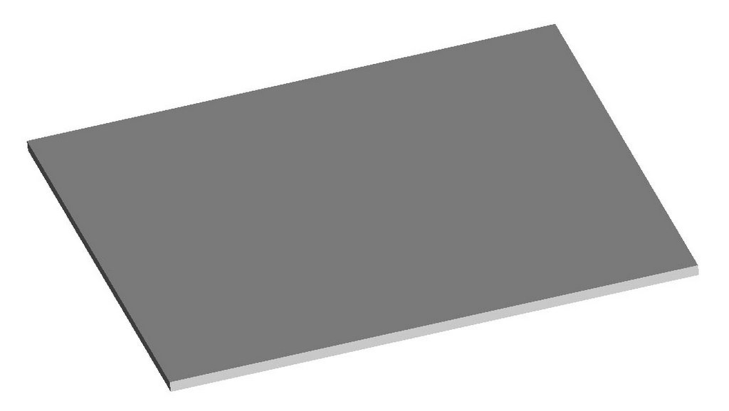
Put down a layer of polymer with your RepRap.
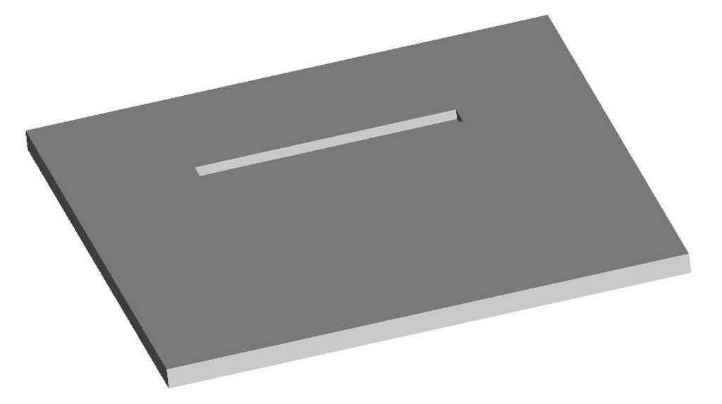
Now put down a new layer on top of it except where you want your conductor to be. Trade your Mk II extruder head for another Mk II that uses fusible eutetic filament for feedstock instead of polymer filament feedstock. Whether it's Wood's metal, Field's metal or any of half a dozen fusible eutetics is purely a matter of taste and local environmental regulations. Extrude your conducting eutectic into the slot in the second layer. Now here's the fun bit.
Trade back to your polymer extruding Mk II and extrude another layer of polymer on top of all that that leaves the tracks where you want the next layer of conductors to go. Notice that I've turned a corner with the conductor at the right and stubbed it on the left. Although the polymer will melt the conductor when you put it down over the conductor it will float on top since it is a LOT lighter than the conductor. Now trade Mk 2 heads again and fill the new gaps with fusible eutectic.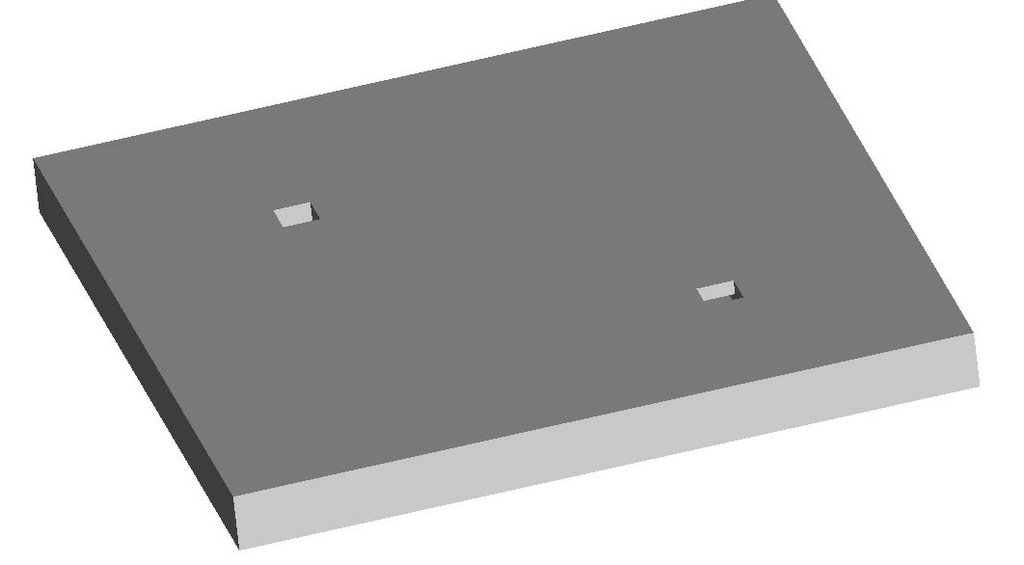
Trade back to your polymer extruding Mk II and extrude another layer of polymer on top of all that that leaves stubs for the two ends of your conductor. Swap over to your fusible eutectic Mk II and fill the stubs. Viola, you've got your conductor trace with the stub ends such that you can dip a soldering iron dialed down to it's lowest heating level into and stick in your components. Your conductor is completely protected by the polymer except where you need to attach components. Given a very high resolution Mk II extruding head this would be a natural for surface mount IC's and components.
Indeed, later on we might think about incorporating the grab and place features of automated PCB board populators into a very sophisticated RepRap and have it fit the components onto the board as well. :-D
Guys, we could fabricate magnetic coils for motors this way.
It doesn't have the same current carrying capacity as a metal but with a little tinkering you could certainly extrude it for at least some of your circuit features. A conductive glue would replace solder. Might not drive a motor but would probably provide static protection and antenna features.

To be honest, I don't think wrapping real wire is going to be that hard.
Vik :v)
The conductivity of the stuff is, as best as I can estimate about 1/15th that of copper, so we wil perforce need larger diameters for at least that if for no other reason.
You've melted this stuff. Do I get the impression that it behaves like mercury? So does lead solder.
I wonder if it would wet better if you mixed a bit of ammonium chloride (a common soldering flux) in with it.
http://et.nmsu.edu/~etti/spring97/electronics/solder/solder.html
So unless we can figure out a better way of making that last little bit, it seems we need to stick to substences with a fairly low melting point rel solder.
My concern for the process is with the converse of the problem stated in the main; if the melting points are similar is there a danger that the metal will melt its way down thru the underlaying polymorph and A: not be properly positioned (too low) to make connections, and B: short out underlying wires if such exist. Perhaps raising the temp of the plastic is a better idea.
1. Would it be possible to, as Vik says, use plain wire? Not so much wrapping it but, say, heating it up a bit and pushing it into the plastic.
2. Instead of extruding molten metal, how about using copper tape and some sort of, um, tape dispenser?
To lower the surface tension, use a metal-filled polymer as an interface layer; I know you've been thinking about dendritic Ag, but maybe Cu or Sn powder would work better. This is the same trick as Sn-plated Cu wire.
That way, you could just dip the thing in Wood's metal at the end, and let the metal stick wherever it wants to.
All in all, though, I think we're best off laying down actual wire, where it's feasible.
as a side benefit to this, it would be ridiculously simple to do wire wrapping... it would already be setup! especially if we're using a turntable setup.
Rotating the wire holder coul dbe made to do a wrapping operation, while a separate mechanism will be needed to cut the wire in such a way that it is ready for the next anchoring operation.
We can also mould projections in the plastic to catch wires, and run wires across or between projections to make sockets.
Vik :v)
http://www.sciencemuseum.org.uk/on-line/ecme/111.asp
Are there any living relatives out there? His priginal name was John Adolphe Szabadi, born in London of Hungarian descent.
<< Home
![]()