Wednesday, October 13, 2010
Story of simpler Mendel: Y and Z axes
My Mendel redesign is slowly reaching first milestone. I have completed a fully working prototype. I already fixed almost all issues that came with building it. Now, my attention turns to doing the basic documentation, then we’re ready to rock'n'roll! I foresee it’s going to be huge success for the Mendel replication rate. All the parts needed can fit and print them all on one Mendel sheet!!!
Z-axis
I chose to use two steppers wired in parallel to one driver. I know, it’s controversial, some people don’t understand it, or even like it. In testing so far, I can find only positive things to say about it vs the regular timing belt design. My hope this blog will open your mind. If you don't wish to try it, you can use older Z axis, the design is still compatible!
Motors are on top side, recessed in holders so they can't rotate, but they are free to self align in X direction. Theres a possibility to secure them with bolts, but I found the its actually much better to let them be free and "secure" them with only something flexible like tape, this together with freedom in X axis arrest really lots of wobble! You cant achieve this with older design.

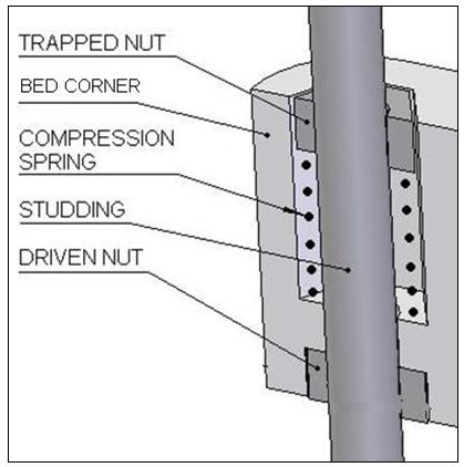
Next great thing is nut trap part of X-end parts. Its clever design I've discovered on Darwin and Im surprised that Im the first who brought it to Mendel. Theory is on picture. In practice it smooths out whole Z axis, since it keeps the nut really securely on the stud.
All together enables Z axis to go upto 260mm/min and probably even faster, but my FW cant handle more steps, since I'm using 1/16microstepping.
Y-axis
I was little scared at first about redesigning Y axis, aware of the parts count and assembly time on standard design I wasn't sure if I can do it more simple. At the end it turned out as simplest axis of all. I even get rid of need for the laser-cutted parts.

Process is very simple, after you install Y axis bars, you snap on four bushings, align them at about the size of the board (12x22cm), put some glue on them and place the board from top. There is no need to be extra precise when aligning the rods, bushings can absorb some error :-)
Rest should be obvious form picture. I've already found better solution tho. Again inspired by Vik! Just use two skate bearings as here http://www.thingiverse.com/thing:2011 , it eliminates idler part and moves half of the belt on top of the smaller board. Unfortunately I wasn't able to test this yet.
Conclusion
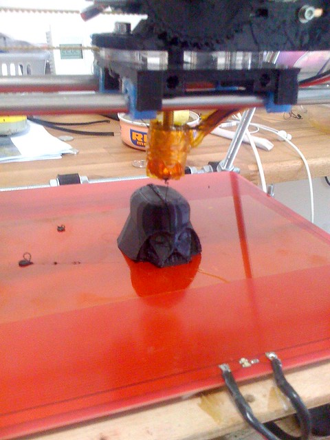
I can print with this machine at 50mm/s without any problem. Objects are as smooth as possible for FDM technology. I will post detailed photos soon, shame I have now only iPhone for taking pics :-(
Most recent files are at my http://github.com/prusajr/PrusaMendel dont forget to watch them. Now I will focus on documentation. Construction is really much simpler, I bet it can be built faster then Makerbot ;-)
BTW Look how awesome these parts look printed on Stratasys from Azdle.

Comments:
<< Home

You say "this together with freedom in X axis arrest really lots of wobble! You cant achieve this with older design." but there is no wobble in the older design, even if the rods are bent, because the axis follows the z-bars. The studding only held at the bottom so
Also the max speed you quote is slower than I get with the old design, I get 360mm / min. It should be faster though as you have avoided the gearing.
I don't mean to criticise your design. The simplification is great but I can't see the performance increases you claim.
The anti-backlash nut arrangement was dropped from Darwin because it isn't needed due to gravity. It adds quite a lot of friction though, so presumably why it did make it into Mendel.
Are you using 200 step steppers here to get enough resolution? What are your thoughts on using 2 cheap lower-than-specified torque 48 step steppers?
1.25 mm/48 steps = 0.026 mm per step before even doing multi-stepping.
Steppers with less than 200 steps regularly are priced at <$5 from several surplus outlets.
Also, could you give a photo on the "nut trap"? The drawing does not show how the tension on the thread is set. I assume you want to take out the backlash but not introduce too much friction. The clever thing about Mendel appeared to be using gravity on the z-axis to remove the backlash, but you claim this is "smooths out whole Z axis". Could you elaborate?
pica - markbova.com
# posted by  : October 13, 2010 2:51 PM
: October 13, 2010 2:51 PM
What happens when you have two stepper motors for Z-axis and one misses a step. Is that not going to cause major problems. Also are they not going to drift apart over time. Can't say I like the idea of using two motors for one axis
Stepper motors don't miss steps if you keep within their specification.
The only time there is an issue is when you power up exactly 2 full steps from the power off position. You then have the chance that each will snap into sync in opposite directions. When I did this with four motors on my Darwin I used pointers so I could see if they were out of sync. But I also used cheap 7.5 degree motors so it would is more obvious.
The only time there is an issue is when you power up exactly 2 full steps from the power off position. You then have the chance that each will snap into sync in opposite directions. When I did this with four motors on my Darwin I used pointers so I could see if they were out of sync. But I also used cheap 7.5 degree motors so it would is more obvious.
A good step towards simplifying things, although I think the anti-backlash nuts on the Z axis are a step backwards - they didn't work well on Darwin (I have two Darwins, which means 8 of those suckers). Too much friction most of the time - in the end I just removed all the upper nuts and springs.
Besides, what's the point of an anti-backlash nut if your motor isn't bolted down? If gravity isn't keeping things tight, I doubt the sticky tape is going to help much.
And as Nophead said, there are zero problems with Mendel's Z axis being wobbly, at least on my machine.
One big problem with having not-perfectly-straight threaded rod coupled to the end of the motor shaft is that your couplers break quite quickly due to the cyclical bending - that was the #1 failure point on my Darwins for quite a while, and this design has two rigid shaft couplings - I'd be interested to see how many Mendels you can print out before it dies.
I'm not sure an extra stepper is going to be cheaper than a belt + some bearings in the long run either, but time will tell.
Antibacklash nut on Z thingy: From what I can compare it seems much sturdier, and when Im printing at 50mm/s even this count for me. I could add possibility for leaving out second nut to design. Second point is, that when you trap the nut badly in nut trap, Z axis can go really hard on standard design. If you dont apply too much pressure on spring, nut will position itself in the easiest position on remix design. (This answered Wades question about the point of anti backlash nuts)
Nophead: Z wobble issue, you maybe don't have wobble on Z but on most pics from internet there is. Point is, you know how to build it, but my mount is very forgiving an will work
Pica: Link for the motors? I would love to try them!!
Keith: Nothing bad, Ive tried to run it with one motor only on one side, It worked but not as smooth. It pushed second motor up. They were not taped down by tape back then. At worst bushings will snap out of the rods or something.
Wade: Coupler wont break since motor is free to "dance" in motor mount, I was thinking that its not good, but you cant see it on the prints and I kinds liked it after few prints so it was accidental hack WIN :-)
Example:
http://www.mpja.com/prodinfo.asp?number=18396+MS
2 Phase Uni-Polar, 6 lead, 12 volts, 3.75 deg per step, 12 ohms coil.
Not square, but the body is about NEMA 22
No other data except the price - $2.95
Holding torque is not rated, but at this price it might be worth the gamble, especially since you share the load between two motors.
Normally this would be unsuitable, but as z is screw driven, it just might be workable.
other styles available of course.
pica - markbova.com
# posted by : October 14, 2010 4:20 AM
: October 14, 2010 4:20 AM
@nophead: You wrote "Also, the max speed you quote is slower than I get with the old design, I get 360mm / min."
Maybe I'm reading either your post or his post wrong, but right after the "Conclusion" heading he says "I can print with this machine at 50mm/s without any problem." 50mm/s * 60 seconds comes out to 3000mm/min. Am I misreading things?
Maybe I'm reading either your post or his post wrong, but right after the "Conclusion" heading he says "I can print with this machine at 50mm/s without any problem." 50mm/s * 60 seconds comes out to 3000mm/min. Am I misreading things?
Yes you are misreading things. He said "All together enables Z axis to go upto 260mm/min and probably even faster, but my FW cant handle more steps, since I'm using 1/16microstepping."
Out of curiosity, why wire the steppers in parallel, rather than series? Isn't drive current more of a limiting factor than drive voltage?
This might be a stupid question, if so please forgive me.
This might be a stupid question, if so please forgive me.
Series connection will reduce the speed because each motor will see half the voltage, so the current rises at half the rate.
In parallel you will get half the torque for the same current but since each motor turns one screw directly is should need less than half the torque of the original Mendel.
Post a Comment
In parallel you will get half the torque for the same current but since each motor turns one screw directly is should need less than half the torque of the original Mendel.
<< Home
![]()