Wednesday, April 29, 2009
Introducting the RepRap Motherboard v1.x
This is another board that has been in development for quite a while that I have done a pretty sad job of communicating to the community about. Well, it's now ready for primetime and a bunch of people have been using them for a while.
The idea on this board is to consolidate the stepper control onto a single board, give it a comms network to control modular 'slave' devices which can control extruders, etc, and also to give it an SD card slot as well as some other cool features. It's based off the Sanguino design.
Anyway, I summed it up much better in the wiki page:
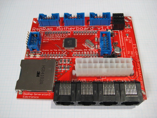
This board is the brains behind the Generation 3 Electronics. The heart is a Sanguino which is an Arduino-compatible board that is powered by an ATMEGA644P chip. It has connectors to hook up all the various peripherals that you'll need to drive a RepRap machine. It has headers for three stepper drivers, as well as 4 RJ45 connectors for Extruder Controller Boards. Not only that, but it has an SD card and a connector to hook it up to an ATX power supply.
Some highlights:
* Onboard atmega644p - 64K flash space, 4k ram, 32 I/O pins, Arduino compatible.
* 3 x Stepper driver connectors with min/max inputs.
* Built-in SD card socket for printing from file and buffering large print jobs.
* RS485 connection for noise-free communications with extruder / toolhead controllers.
* ATX power connector for power. It can also turn the power supply on and off.
* Headers to allow existing Sanguinos to plug straight in.
* I2C headers for simple hookup of external peripherals.
* On/Off switch for instant-kill and simple control of the entire system.
This board was developed by the RRRF and is available for sale from MakerBot Industries as a kit. They will also be available fully assembled in a month or so.
Comments:
<< Home
Great work Zach. I ordered two copies about a week ago (right after you announce the controller board on the blog).
One question though, I hacked my computer power supply to get it to work with my Gen 2 electronics. Thus my power on and a ground wire are removed and bound together. Will this just mean that the power button is non operational, or will it put the board in danger not having all the grounds attached.
One question though, I hacked my computer power supply to get it to work with my Gen 2 electronics. Thus my power on and a ground wire are removed and bound together. Will this just mean that the power button is non operational, or will it put the board in danger not having all the grounds attached.

A number of design comments:
- How about using Ethernet for communication between the host and the controller board? It's a standard protocol, uses magnetic decoupling and is much more flexible in terms of topology than USB. Chips like ENC28j60 are through hole and easy to hook up to the AVR. Nophead originally pioneered this idea for his repstrap and I've been successfully using an eth on mine.
- I'm not sure I see the sensibility of hardwiring the power connection to an ATX power supply. The connector takes up a lot of space on the board and it makes it very hard to connect any other kind of PS to the unit. Why not make the power connection more generic and potentially add a breakout board with the ATX connector?
- This must have been argued before, but using the rj45 jacks for RS485 seems to be asking for trouble. An alternative would be to export these as normal headers and let whoever builds the enclosure decide on what the actual connectors should be.
those are very good suggestions. barring major bugs, i think the next major rev is going to be v2.0 and i'd love to incorporate changes like that into it.
with the release of the arduino mega, we have an obvious candidate for the chip on v2.0 as well.
with the release of the arduino mega, we have an obvious candidate for the chip on v2.0 as well.
I'd like to jump in for the defense of the RJ-45 headers. They're great!
Ethernet cables are quick and cheap, and an order of magnitude more reliable than cables I individually crimp myself. The socket mounts to the PC board, it's all win.
Ethernet cables are quick and cheap, and an order of magnitude more reliable than cables I individually crimp myself. The socket mounts to the PC board, it's all win.
Great work, Zach.
Perhaps a stupid question: would this board be able to communicate with a twin device, out of the box -- could it be a daughterboard to another motherboard?
Perhaps a stupid question: would this board be able to communicate with a twin device, out of the box -- could it be a daughterboard to another motherboard?
For the rj45's we could use a similar system to Power Over Ethernet ( http://en.wikipedia.org/wiki/Power_over_Ethernet )
Where a known resistance is placed between two of the pairs and probed for, using a low voltage, before applying power. Using a diode instead might be better as the non-linearity wouldn't be effected by cable length.
Where a known resistance is placed between two of the pairs and probed for, using a low voltage, before applying power. Using a diode instead might be better as the non-linearity wouldn't be effected by cable length.
I am not sure what issues people have with using 8P8C connectors, they are cheap and easy and quite robust. Unless we want to invent our own connector type and make our own cables, we are going to have to reuse some existing system.
When it comes down to it, people are building these things from scratch, they can figure out that you need to plug cables into the correct places. If they are worried about some random person not realizing it isn't ethernet, they can put a dab of hot glue on the connector to keep it in place, or solder some proprietary connector in its place instead (it is open source after all). No need to complicate the base case though.
Post a Comment
When it comes down to it, people are building these things from scratch, they can figure out that you need to plug cables into the correct places. If they are worried about some random person not realizing it isn't ethernet, they can put a dab of hot glue on the connector to keep it in place, or solder some proprietary connector in its place instead (it is open source after all). No need to complicate the base case though.
<< Home
![]()