Monday, April 20, 2009
Introducing the Extruder Controller v2.2
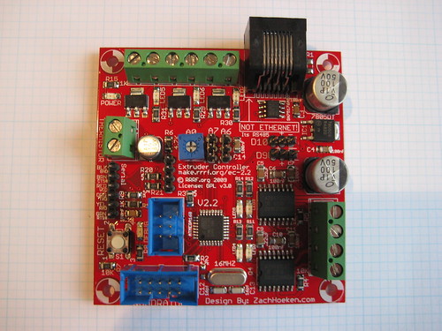
This board has been under development by the RRRF for quite a while, and it's gone through a few different revisions before I felt it was ready for prime-time. This board is a major component part of the new Generation 3 RepRap electronics, and I'm really happy with how it turned out. You can read the full documentation on the board on the RepRap wiki. Oh yeah, and the design is up on Thingiverse if you just want to check out the files quickly.
One of the major problems with the Gen2 electronics is that everything was running on a single Arduino, and that chip just didn't have the power, the pin count, or the memory to run a RepRap machine really nicely. So, with Gen3 I decided to swing the pendulum back a bit towards the Gen1 boards which were completely distributed. With the Gen3 stuff, its a happy medium: there is a motherboard (which I'll blog about later this week) that can control various slave devices (such as this Extruder Controller). Each of them has its own processor, so they can do things independently.
For example, with the old system, we had to have a temperature check in the same loop that was doing the stepping algorithm. It had to check the temperature between every step otherwise it would either heat up too much or cool down on long moves. This resulted in a slowdown at faster speeds which was really a pain in the neck. However, with the new system, the Extruder controller is responsible for handling temperature and the Motherboard basically just sets it and forgets it. It simplifies the design of both firmwares and life is good overall.
To get into some nitty gritty details, the Extruder Controller v2.x boards have an Arduino onboard (atmega168) and use RS485 to communicate with the motherboard (noise tolerance!). Here's a blurb from the wiki where it has been fully documented:
* Onboard atmega168 - program it just like an Arduino because it is an Arduino.
* 3 x MOSFET drivers for controlling up to 14A @ 12V. Perfect for heaters, fans, solenoids, etc.
* 2 x H-Bridges capable of up to 2A each. Control 2 motors, or control one stepper motor.
* A temperature sensor circuit for reading the standard 100K thermistor.
* RS485 connection for noise-free communications with the motherboard.
* IDC header for connecting a Magnetic Rotary Encoder.
* Polarized ICSP header for simple, easy programming.
* It mounts directly to the Pinch Wheel Extruder!
* It is plug and play with the RepRap Motherboard.
If you want to use one on your machine, you can get a kit from the MakerBot Store. It is a SMT based board, but don't let that scare you off. It's actually pretty easy to get it soldered up. If you absolutely refuse to do SMT, we're planning on having them fully assembled in a couple of months which will make things easier.
Comments:
<< Home
This board seems like a great robotics experimentation platform as well. it has everything you need to be the brains of an interesting robot.

Great to see. Getting around the huge tangle of wires that my 2nd gen has got will be great when building my next machine.
One question I just want to confirm though, are all the chips available as a through hole design? After discussion in the previous post, it looks like for now repraps will only be able to get the resolution to make through-hole designs in the near future (the next year or 2 at least until we get the solder control problem cracked).
I know the main reason for the move to surface mount was the size of the boards though.Since through hole boards produced will probably be about 3 or 4 times the size, but would in theory probably work well.
Hi. I'm an FPGA designer. The smallest, $4 FPGA would be able to do everything you need and then some. If you would be interested in putting a board together, I'll help program it.
brian dot korsedal at gmail dot com
brian dot korsedal at gmail dot com
I have always been curious about fpga programming. It seems that other than the CPU, most of the other parts are things like h-bridges and power mosfets, can an FPGA handle that sort of thing? As in, what do you envision an extruder controller board based on FPGAs looking like? I am not sure I see a win if the FPGA can't replace anything but the arduino chip.. but perhaps we can reduce the vitamin variety to a bag of power mosfets and nothing else or something...
Post a Comment
<< Home
![]()