Monday, January 12, 2009
Pinch Wheel Extruder Prototype
 Ever since reading Lou Amadio's blog entry on an idea for a pinch-wheel extruder, I've had the idea stuck in my head. One of the consistent problems I've had with building a RepRap has been the extruder mechanism: its either super complicated, needs machined parts, or usually a combination of both. When I saw the simplicity of this design, I instantly loved it. However, I didn't know what motor to use on it, so the idea went into the 'rock tumbler' portion of my brain.
Before even starting a design, I wanted to make sure that it was feasible. Going to a direct drive of the filament means that you need a motor that goes really slow... but how slow? Well, glad you asked. I created a Google Spreadsheet with formulas relating to filament feedrate. There are three different things I looked at: Driven Screw based extrusion (how things are now), Pinch Wheel Extrusion (what i wanted to experiment with) and finally how the filament feedrate actually translates into extruded filament. Luckily for me, nophead had posted most of the formulas to the reprap mailing list, so I just had to setup the spreadsheet.
So, what did I find out? Pinch wheel extrusion *is* possible, but you need to hit two important criteria: 1) an RPM of 2 or less, and 2) a pinch wheel diameter of less than 15mm, ideally under 12mm. At these numbers, you get 1.26mm/sec of filament extrusion. With a 0.7mm nozzle, you get 23.08mm/sec of extrusion. This is really fast, but thats okay.
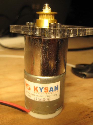 This was all just a random reprap idea in my head until a few days ago, when I got a shipment of DC gearmotors from Kysan. Randomly, I managed to pick up an extremely lucky motor: it is geared down something like 600:1 and thus rotates at 2 RPM. This also means it has a lot of torque. I started on a filament feed prototype yesterday and got a working model.
Unfortunately, the model had some flaws! I really had no idea what to use for the actual pinch wheel. I tried about 5 different things until I found one that worked reliably. I'll list them below so you can learn from my mistakes:
Fail: Acrylic wheel w/ a rubber band glued on. I figured since rubber grips on ABS pretty well, it would work okay. It didn't. It slipped when I applied any sort of 'realistic' force.
Fail: Acrylic 'gear': I tried a variety of lasercut 'gears' with little teeth cut in a variety of profiles. If I didn't push the idler wheel in tightly enough, they would just slip. If I pushed it in too tightly, they just cracked and broke.
Fail: Dremel sanding wheel. I noticed a sanding wheel from a Dremel laying around. It was slightly bigger than the shaft of the motor, so I used a dab of hot glue to attach it to the shaft. I figured that at such low speeds, it would simply grip the filament... which it did. Until it slipped, then it just turned into a super-slow filament sander, lol.
Fail: Tiny belt pulley from McMaster. This pulley wheel was the proper diameter, but the hole to mount on the motor was too small. I decided to drill it out bigger. Well, I basically destroyed the belt pulley.
Win: Slightly larger belt pulley from McMaster. This pulley wheel had a 1/4" (6.35mm) bore which was just slightly bigger than the 6mm motor shaft. A bit of masking tape to keep it properly aligned and it fit perfectly. It has set screws, so it is *very* firmly attached, especially with one set screw on the flat of the motor shaft. This setup was super strong. I had to use quite a bit of man-force to keep it from pulling the filament in. Seriously awesome.
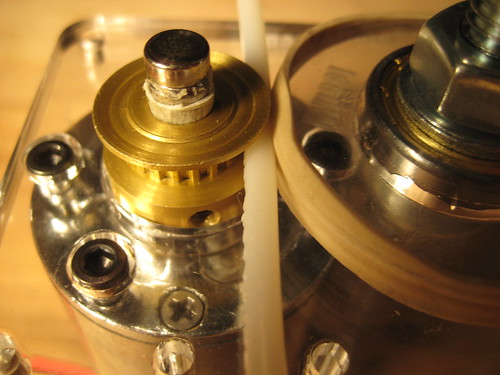 If you look at the pictures, you can see that the pulley wheel actually imprints its tooth profile onto the plastic, which turns the plastic into a sort of matching gear, giving it some serious grip strength. I think that this is the key to getting a good, solid filament drive. There are a few downsides to the pulley: 1) its slightly too big, but McMaster doesn't sell a smaller pulley with the same bore size. 2) the tooth profile is not very sharp. with a sharper tooth profile, it would probably have a much better grip vs the blunt profile.
I'm very happy with how this design turned out: it has very strong filament output, it is a *super* simple design, and everything except the lasercut parts are things you can buy on McMaster.com (or hardware store)
The next step is to modify the design to mount the heater barrel stuff to it, but that should be easy since the lasercut extruder design by Ian has a really nice design for that already.
Oh, and I need to do 2 other things: 1) modify the design to allow super easy mounting of the magnetic rotary encoder and 2) modify the design to allow super easy mounting of the new extruder controller board, which is in prototype stage right now.
Anyway, if you want to check out the design files, they're up on Thingiverse or in RepRap subversion in my home directory.
Cheers!
Zach
Comments:
<< Home
This is great! I'm getting my McWire up and running, and I've been waiting to see if something new came up for an extruder. The current one just seems too complicated. I think I'll wait a little longer and see how this turns out.

McMaster is great for raw materials and a lot of other stuff, but it's not the best for little pulleys..
Stock Drive Products/Sterling Instruments www.sdp-si.com sells plenty of metal timing pulleys with 6mm ID, with ODs actually all the way down to 10.3mm)
part A 6A51M017DF0306 at the site has a 10.3mm OD, 6mm bore, and is meant for a 3mm wide belt. One is $10.40, down to $5.62 for 100, and all the way down to $4.31 for 500. There are also 6mm and 9mm wide versions, strangely the 9mm is actually the cheapest for one piece, the 3mm is cheapest for bulk, and the 6mm is the most expensive all through..
They also have polyurethane feed rollers, which I'm planning to experiment with when I start putting an extruder together.
It would be interesting to try this on some PLA filament and see if the harder plastic still feeds.
Vik :v)
Vik :v)
Lol you're welcome.. I was also going to suggest the possibility of a switch to steppers, but that would require a new low-current stepper board - this doesn't really justify a full-on L297/298 combo.
Glad you're trying out pinch wheels. Thanks for writing what works, what doesn't and why.
The Stock Drive Products/Sterling Instruments store seems excellent. They also have metal gears, which are cheaper than timing pulleys and I believe, should grip as well. The downside of gears compared to pulleys is that gears don't have a groove to keep the filament in. However, adding a groove to the paired smooth pulley wheel should keep the filament on the gear.
Their 12.5 mm steel gear is 9.80$ for 1, down to 3.61$ for 100:
https://sdp-si.com/eStore/PartDetail.asp?
Opener=Group&PartID=25496&GroupID=590
The metal gears parts lister can be found in the navigation tree on the bottom left of the page:
https://sdp-si.com/eStore/
under the heading:
Gears -> Spur Gears -> Metal
That looks pretty sweet! Is there a way to adjust the tension for different filaments or gears? I suppose you could just cut out a few different sized idler wheels on your laser cutter. I knew I should have asked for a laser cutter for Christmas!
he Zac, I've posted some pics of a commercial variant of what you've just made, which is designed for "wire", as I thought it might inspire you/others to keep up the good work!
If you are planing on making an order to Stock Drive Product/Sterling Instruments I strongly suggest purchasing a set of ratchet wheels. Like part number (A 1B14-24024). They may only drive well one way, but hey, they should have no problem driving any polymer, they just have the right shape. There are lots of us working on a pinch wheel extruder right now.
enrique: yup, i got a couple of gears, and a couple of the pulleys. i'll post an update with what works best in a few days.
wade: yes, the idler wheel is on a slot... you can easily adjust it closer or further from the drive gear
geo: the ratchet profile is actually *exactly* what i need. unfortunately for us, they don't make them small enough. we need metal ratchets that are 12mm in diameter or smaller. can anyone find me one or a source for one? ideally it has a 6mm bore and a set-screw. might be tough to find...
For ratchet wheels, toward the bottom of the catalog at:
http://www.ofrei.com/page_6.html
you can buy the 12 mm ratchet wheel, the CLK-7850R-12.0, for $8.00.
Another place to get em is from the timesavers:
http://www.timesavers.com/catalog/index.htm
in the Gears, Cams and Wheels catalog at:
http://www.clock-keys.com/pdf/Categories/
gears%20cams%20&%20wheels.pdf
the 12mm No. 19844 is available at $4.50.
Unfortunately the ratchet wheels are really thin, for example the No. 19844 is only 2 mm thick.
So the reason for wanting a smaller diameter pinch wheel is because the velocity of the output shaft, yes? And you are going to have encoder feedback?
If you are going to have encoder feedback, then it doesn't really matter if the motor is too fast! What matters is the resolution of the encoder, and the torque the motor can produce. The whole idea of a closed loop control is that you can change the dynamics of the system without changing the actual system.
By the way, we should be trying to mount the encoder on the motor shaft, not the output shaft. That will solve lots of problems. If you had even a 24 ppr encoder on the motor shaft, that gives you 14400 ppr on the roller. You could drive that motor well below a 0.1 rpm and still have excellent control.
If that is the case you can change from the tiny roller 12mm to a 30mm roller and still have the ability to go slow, and fast! Both speeds will feed with awesome regulation.
enrique: yeah, the problem with those ratchets is that they are too thin, with funky mounting holes. i submitted some quote requests to gear makers to see if they will make us some custom gears
geo: yes, with encoder feedback we will be able to slow it down, but you can only slow it down so much before the motor stalls out or becomes jerky. i think its best to design so it works ideally within your range, then use the encoder for precision control within your desired parameters.
geo: yes, with encoder feedback we will be able to slow it down, but you can only slow it down so much before the motor stalls out or becomes jerky. i think its best to design so it works ideally within your range, then use the encoder for precision control within your desired parameters.
Ah yeah! Nice zach, nice. And the rubber must be a bit more forgiving on irregular diameter filament than the nut idea Steve and I've been trying.
I like this idea, given it's much easier to create massively parallel systems with this design. I'm planning a minor project fork and this design can pretty easily be altered to mean you can fit either 2 or 4 extruders in parallel without having the redesign the whole axis system.
ed: yes, also the idler wheel is in a slot, so it can be moved back and forth before tightening it down. The rubber on the idler wheel gives it an extra bit of springiness.
letsburn: why fork? just contribute to the project directly. all ya gotta do is publish your modifications. =)
letsburn: why fork? just contribute to the project directly. all ya gotta do is publish your modifications. =)
Um... this is all wonderful stuff, but I was looking at the data sheet for that Kysan gearmotor and although draws zip in the way of current it weighs in at half a kilogram. By the time you got the rest of the extruder parts assembled I suspect you're talking about a finished extruder weighing in at anywhere from 750-1000 grams.
Now that can probably be made to work on a Tommelise positioning system or one like Ed is currently designing at Bath university, but that is a LOT of inertia to put on Darwin's xy positioning rig.
Now that can probably be made to work on a Tommelise positioning system or one like Ed is currently designing at Bath university, but that is a LOT of inertia to put on Darwin's xy positioning rig.
Where did you find the data sheet?
From what I'm reading, it's about 200 grams - http://www.kysanelectronics.com/Products/Detail.php?recordID=6987 shows a 1.5 rpm model.
From what I'm reading, it's about 200 grams - http://www.kysanelectronics.com/Products/Detail.php?recordID=6987 shows a 1.5 rpm model.
Beagle,
I read the SKU# off of the pic in Zach's article and then looked it up on the Kysan site.
http://www.kysanelectronics.com/Products/datasheet_display.php?recordID=2055
Mind, Zach has one in-hand that he can look at and weigh himself. It's possible, I suppose, that Kysan list the shipped weight on their data sheet. I doubt that, though.
Brilliant Zach :-)
Gear groove - might be possible to spin the gear in a Black and Decker then simply hold a rat-tailed file against it. It'd spread the teeth a bit, but I expect they'd still grip.
Any idea what sort of torque you need? Clearly quite high, but I was wondering if it could be driven by a geared-down small stepper.
Is the idler pinch-wheel floating and sprung against the drive? That might be a way to accommodate variations in the filament.
forrest: yes, the motor weighs quite a bit. its also total over-kill. we should be able to find a suitable motor that weighs half that but is still torquey enough. i'm going to attach it to my RepRap machine tomorrow and we'll find out if it is indeed too heavy or not. bottom line is that this filament drive system is drastically superior to the screw driven style. finding a proper motor is easy.
adrian: no need for a groove in the gear. infact, i bet filing down the teeth would decrease its ability to drive filament. the reason it has such good filament driving capabilities is that it actually presses matching tooth profiles into the plastic and then uses those to drive it.
no idea on the torque, but the motor has no problem driving filament. i'm going to try and spec a smaller, lighter motor and we'll find out if that helps or not.
finally, the idler wheel (you can find all this info in the design files, btw) is in a slot cut in the acrylic. it can be moved towards and away from the pulley wheel, and when you get the proper tension, you tighten it down into place. its *very* simple to adjust, and can easily accomodate various filament thicknesses. it might not handle filament with a varying size on the same strand, but if thats the case... you should get better filament ;)
update: the gearmotor is 265g w/ the aluminum pulley attached. by comparison, the GM3 is 30g, but its also mostly plastic.
if anyone can spec a similar motor (12v, 2-3 RPM, etc) that would be excellent.
if anyone can spec a similar motor (12v, 2-3 RPM, etc) that would be excellent.
Zach: the semi-fork(not as in a seperate project, but a sub-type of darwins using this as a design mod) was originally planned to create a semi-miniaturised version of the system in which beginning with 2, then later maybe 4 smaller sub-areas would operate on the same stepper motor control drivers working in parallel where the movement on one stepper would be transmitted to 2 or 4 extruders. Each "cell" would have shared walls or corners to reduce parts but the stepper motor driver would push each cells extruder along the X,Y axis at the same time. The idea being that the production volume would be much reduced, but it would be large enough to produce parts for a normal sized machine(bar perhaps the main carriage on the X axis). Basically it was a system for increasing the replication rate of normal machines. I was going to call it "the motie" version(after the sci-fi species that reproduces like crazy). Only the extruder would need to be replicated.
i.e Darwin slowly makes a motie by making parts one by one. Motie makes darwins very fast by building 4 copies of a part at once. A Motie is like a miniature darwin that is much better at mass producting darwin parts as opposed to actual objects. It was brought about after I gave a presentation on repraps at a sci-fi con and had a dozen people asking me for printed parts.
The point of my original post of course, is that it won't be needed at all, since this extruder design looks much more amiable to running in parallel. I can just combine 2 or 4 of these (as seen in the original post on the design) and make parts really fast once I get a controller board thought up for controlling multiple systems at once. The issue is currently moot for me, given I'm being driven insane by getting my bits from bytes machine working.
I was looking at the builders blog post on a commercial pinch wheel setup from a welder and a thought occurred - we've kept the extruder motor on the toolhead, but it doesn't have to be there. The welder feeds its wire up through a tube so that the operator doesn't need to carry the heavy motor and pulleys around. It seems like something along the lines of aquarium tubing or another plastic/rubber tube could do the same thing for us. The biggest problem would probably be the transition to a new spool of filament, but if the tube ID is close enough to the filament diameter the new filament will be able to push the remainder of the old down the line. If it works, it would have the added bonus of making the extruder on the bot smaller, which would make it easier to double up to add a parallel head with a larger extrusion size.
example of tube that could concievably work: McMaster part number 5733K54 is a hard, clear (so you can see the filament) tubing with a 4mm ID, minimum of 1" bend radius, rated to 500 degrees F (260 degrees C). $2.65 a foot.
example of tube that could concievably work: McMaster part number 5733K54 is a hard, clear (so you can see the filament) tubing with a 4mm ID, minimum of 1" bend radius, rated to 500 degrees F (260 degrees C). $2.65 a foot.
Corwin, neat idea, but I'd guess that you'd need a nozzle valve with that setup, as the tubing and the extra length of plastic filament under compression is going to compress like a large spring, causing a lot more ooze and startup delay than normal. MIG welders have very stiff tubing, stiffer filament, and almost no nozzle pressure.
But hey, give it a shot and see how it works - that's the real test!
But hey, give it a shot and see how it works - that's the real test!
Zac, I've posted details of another motor option for you that would be perfect for the pinch-feeder. ( on the builder blog) I've seen these in person, and they are a great little unit.
Buzz.
Buzz.
laser cut pinch pull extruder in progress:
http://prometheusfusionperfection.wordpress.com/category/hercules-extruder/
http://prometheusfusionperfection.wordpress.com/category/hercules-extruder/
I think I would be a bit worried about the radial force on the motor bearing. I assume that it must be pretty high to press the cog into ABS. In which case I wouldn't expect the bearing to last very long. I think it would need something hefty like a skate bearing.
American Science and Surplus has a few geared motors that are close - 4-7 rpm at full voltage, and under $20.
Item 37739 on http://www.sciplus.com/category.cfm/subsection/18/category/172 looks promising.
A gear meant to mate to a worm drive may have smoother output - no diameter changes, profiled to mate to a round object, and avg cross-section of the filament should be consistent due to helical hashing.
As for the question of filament diameter and adjustment, if you put the skate/idler bearing opposite on a shaft long enough to put strong springs/elastics like section of surgical tube stretched as a rubber band from either end of the axle to pins near the motor, it should self-adjust, no?
Looking forward to playing with this myself when time allows.
Post a Comment
Item 37739 on http://www.sciplus.com/category.cfm/subsection/18/category/172 looks promising.
A gear meant to mate to a worm drive may have smoother output - no diameter changes, profiled to mate to a round object, and avg cross-section of the filament should be consistent due to helical hashing.
As for the question of filament diameter and adjustment, if you put the skate/idler bearing opposite on a shaft long enough to put strong springs/elastics like section of surgical tube stretched as a rubber band from either end of the axle to pins near the motor, it should self-adjust, no?
Looking forward to playing with this myself when time allows.
<< Home
![]()