Friday, December 19, 2008
Paste extruder motor test
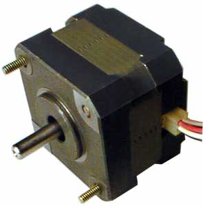
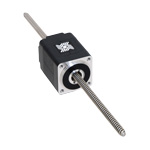
I wanted to find out which motor lends itself best to a paste extruder design. I came up with some rough prototypes and pitted Fab@Home's non-captive stepper from Haydon (left) against our old favourite, the Solarbotic GM3 servo (right).
.JPG)
Both designs worked great, however, the non-captive stepper design was radically simpler with significantly less fiddle and faff (hats off to Evan from F@H for going with this principle). Unfortunately, this particular non-captive stepper (Haydon, 28000 series) is worth $100+, and with cost of the RepRap an ever-pressing issue, we are investigating cheaper non-captive alternatives. From the design point of view non-captive is the answer. Could we make the GM3 non-captive?
Adrian demonstrated a great hack to convert a captive stepper into a non-captive by boring a clearance hole into the shaft and leaving an internal thread on the last few millimeters:
.jpg)
Investigations continue...
Comments:
<< Home
Aside, if we can hack a non-captive onto the GM3 and somehow prevent the filament from rotating, that would make for a *damn* simple thermoplast extruder. Sprung pinch wheels below perhaps?

This is somewhat beyond the scope of this post, I know, but what *is* the difference between a captive and non-captive stepper motor?
A captive stepper motor has a fixed shaft attached that rotates. A non captive stepper motor has a hole through with rotating threads, and a threaded rod that is put through the middle, if I understood it right. So a non-captive stepper motor is ideal for threaded drives, I believe Forrest is using them for his 3D printer Tommelise for example.
Pictures:
Normal captive
Non-captive
Pictures:
Normal captive
Non-captive
I'm going to take the final drive out of a GM3, make a silicone mould for it (see http://dev.www.reprap.org/bin/view/Main/SoftToolingForCasting), and cast a replacement with embedded M3 nuts...
Oh no I'm not...
Just taken it apart. The final drive includes a co-axial idler shaft on which one of the other pinions rotates, making running a thread down the middle virtually impossible...
Just taken it apart. The final drive includes a co-axial idler shaft on which one of the other pinions rotates, making running a thread down the middle virtually impossible...
"Aside, if we can hack a non-captive onto the GM3 and somehow prevent the filament from rotating, that would make for a *damn* simple thermoplast extruder."
How about:
A) Two counter-rotating, coaxial gears: one with an M3, one an adjustable friction clamp.
or
B) A single M3 nut, plus a scalpel blade mounted to cut a longitudinal groove
How about:
A) Two counter-rotating, coaxial gears: one with an M3, one an adjustable friction clamp.
or
B) A single M3 nut, plus a scalpel blade mounted to cut a longitudinal groove
Adrian, et al,
For the non-captive mechanisms, what prevents the threaded shaft from rotating with the rotor?
I'd guess there'd be some sort of spline groove cut into the threaded shaft, with a stationary (mating) spline/key resisting rotation. However, I don't see any such in the photos. How do they prevent shaft rotation?
-- Larry
Tests show that the seal friction in the syringe is more than enough to prevent shaft rotation (nice bonus!) - and the bigger the syringe diameter, the better this gets.
Steve, like scalpel idea!
Steve, like scalpel idea!
I have an solution for this problem. I made a solid model and put an animation on Youtube:
http://www.youtube.com/watch?v=Uf3X22RsufY
If the animation is not clear I can make a drawing. Simply put, the motor and the captive nut are separated by a tube that transmits the torque. Let me know what your think.
http://www.youtube.com/watch?v=Uf3X22RsufY
If the animation is not clear I can make a drawing. Simply put, the motor and the captive nut are separated by a tube that transmits the torque. Let me know what your think.
Syringe dispensers very cool. great for solder paste dispensing and possibly pick and place.
# posted by  : December 21, 2008 1:48 PM
: December 21, 2008 1:48 PM
Geo, that's great! One day all mechanical explanations will be that slick ;-)
I like the solution... obviously not as compact as a direct non-captive shaft, but still it does the trick.
Post a Comment
I like the solution... obviously not as compact as a direct non-captive shaft, but still it does the trick.
<< Home
![]()