Sunday, October 12, 2008
RS485 Circuit = Success
 Recently, I've been working on the 'Generation 3' electronics based on the Sanguino / atmega644p chip. This new generation of electronics sets out to solve many different problems with the current electronics: modularity, simplicity of wiring, microprocessor power, as well as adding many new features: sd card support, lcd support, interface support, and much more. This next generation of electronics is a large topic, which I will cover in future blog posts, but for now I'd like to focus on one particular feature: the data bus for the modular extruder system.
If you remember back to the days of the Generation 1, PIC based electonics we had a token ring system where each part of the system had its own microcontroller and was connected via TTL serial. This system suffered from many flaws, including noise in the serial lines connecting the various microprocessors.
The Generation 2, Arduino based electronics fixed this by swinging to the opposite end of the pendulum: all the electronics are controlled by a single microprocessor and no serial data connections are required (except to the computer). The main disadvantage to this is that the Arduino is pretty underpowered to drive a complex system such as a RepRap machine. We managed to do it, but we had to take quite a few shortcuts. This basically means we're also pretty limited in the things we could achieve.
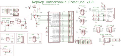 The Generation 3, Sanguino based electronics will swing back towards the middle, using a 'best of both worlds' approach. It uses a more capable microprocessor which solves the memory and pin problems. However, even with more pins its is still tricky to drive more than 2 extruders, or one extruder and an LCD screen / button interface. Thus, we need a modular system to allow expandability.
This long winded intro brings me to the subject of this post: RS485. This is a serial communications specification that uses differential signaling. The awesome thing about this is that it offers many cool things, one of which is improved noise immunity. As the wire contains the same signal twice (once normal, once inverted) When it gets to the other end, and the inverted signal is transformed into a non-inverted signal and combined with the original signal. Any electrical noise that was picked up is then cancelled out due to wave mechanics. Cool, huh?
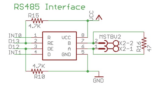 I'm not an electrical engineer, so this stuff is all pretty new to me. Fortunately, we have many smart people participating in the RepRap project with experience in many different areas. One of those people is Nophead, who you may remember from his excellent HydraRaptor machine. He might deny it, but he's an electrical genius and he gave me a chip number and a circuit for doing RS485 communications. Today I built and assembled it.
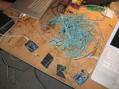
In the picture you'll see the eventual setup I had going. I wired up two RS485 circuits to two Arduinos, and wrote a quick sketch to get them talking. The connection was a very long long, unshielded, twisted pair cable from an old ethernet cable. I hooked all these up and started them communicating. It worked great! I also did a test to try and inject some noise into the system by operating a powertool right next to the wires. It was very unscientific, but the RS485 connection didn't skip a beat.
There was one problem that I ran into, which was easily fixed. The Arduino only has one hardware serial port, which was being shared by the RS485 chip as well as the FTDI usb -> serial converter chip that is on all Arduinos. The problem was that when uploading a new sketch to the arduino, the RS485 would also be sending and receiving data which would seriously mess with the uploading process. Luckily, the RS485 chip has both a transmit enable and a receive enable pin. I used the appropriate pullup/pulldown resistors to default these both to off so that when the Arduino was reset for the upload process, the RS485 was disabled. This means that I had to wire up an additional two pins on the arduino to control the RS485 receive/transmit status. This is not a big deal because using RS485 frees up a lot more pins than it uses, so there will be plenty of pins available.
Anyway, today was a good day of hacking. Hopefully later this week I'll be able to wire up the SD card and run it through its paces. Luckily for me, there are schematics and code already written for the Arduino all over the internet, which means that it will be fairly trivial to wire it up and getting it working on the Sanguino.
Comments:
<< Home
Hello,
great article on RS485. I worked on lift controllers and we used RS485 for group controllers, communication with the car and Remote monitoring.
There are a few points you must be aware of:
-the speed of the network is dependent on the distance (rule of thumb 9600bps - 500m).
-a termination (active/passive) network is needed if distance >50m and speeds >9600bps.
-you must have a common ground connecting both interfaces.

P.S.
Zach, Amzing work!
how do you become so awesome in electronics?!?
(seriously where did you learn this stuff?)
Zach, Amzing work!
how do you become so awesome in electronics?!?
(seriously where did you learn this stuff?)
Hey, Zach:
Great work! I like the idea of RS-485.
I'm still on the PIC bandwagon over here. I like RS-485 because I suspect that there may be a world in which sanguino/argudino and pics co-exist.
I love my pics for some applications-- example 1 is motor control. you just cannot beat an 18f4431 for that application-- is has hardware quadrature encoder readers, and pwm generators.
great thing about rs-485 is that just about every uC has one or two UARTS in it, and a simple level converter allows RS 485 with no trouble.
You were talking about multiple devices-- are you going to allow multiple devices to share the rs-485 bus? If so, will you use SNAP or another approach to share the medium?
My first job was for a company producing test gear for car factories. At the time, the ECUs in cars (ABS, steering, motor control, etc.) all used RS485 - but were slowly on the path to migrating to CAN. This solved their problem of wiring frames becoming ever more complex as the number of ECUs multiplied.
It's probably too complex a system for RepRap, but the problem space does strike me as similar. Due to the heavy usage in automotive applications, there are also very many parts capable of CAN. It might be worth a look.
It's probably too complex a system for RepRap, but the problem space does strike me as similar. Due to the heavy usage in automotive applications, there are also very many parts capable of CAN. It might be worth a look.
thanks guys!
leav: thanks. i'm certainly no expert: i just know enough to be dangerous. luckily there are others on the team that did the real work of finding the proper chip, etc. that allowed me to do this. other than that, its just lots of reading: theres a ton of information on the web, and i learned by reading, doing, and playing.
dave: thanks as well. =) ideally we can have a hybrid world with a common interface that users can use to add compatible devices to. i'm an AVR fan myself, but i'm all for compatibility. cheers! i think the idea is to have multiple devices on one RS485 line. we'll probably have to have one 'master' and the rest be 'slave' devices or some such. first i want to get the physical/electrical layer right. then its all software =)
jon: i believe nophead looked into CAN, but it seems fairly expensive (~$10/chip vs. $0.80/chip) i could be wrong though.
Zach at al,
Are the noise problems so severe that they can't be dealt with by shielding, star grounding, and a few ferrite beads?
RS485 is useful, but can get tricky, especially if used as a multi-drop network (more than two devices communicating -- probably our case eventually.) Here is a link to a good article about one RS485 pitfall, and how to avoid it.
http://www.rmbconsulting.us/Publications/TxEnable.pdf
This is by my former colleague, Nigel Jones, a seriously sharp guy.
HTH,
Larry Pfeffer
ursine at gmail d0t c0m
larry,
thanks for that excellent tip!
luckily for us we are using the exact chip he specifies, and we are also giving full control over both enable lines to the sanguino which means we can easily implement his final suggestion.
i'll certainly look back at this pdf when it comes time to implement the comms.
cheers!
Ah, the old RS485 vs CAN argument. I think you went the right way for the current design. You'd have to switch to a controller with an embedded CAN controller to reach price parity, but that is a rare Atmel chip. I just don't like being forced on some chips to run a specific baud rate to get a stable async network connection.
CAN does bundle up all the low level timing and maintenance issues into a single hardware controller, but if CAN does become an option (I see it more from the PIC-Alternative branch of research) I'd expect it to be added in a shield or as a standalone bridge module. Frankly, if boards needed an external controller, might as well use an ENCJ60 and wire everything up over true Ethernet.
CAN does bundle up all the low level timing and maintenance issues into a single hardware controller, but if CAN does become an option (I see it more from the PIC-Alternative branch of research) I'd expect it to be added in a shield or as a standalone bridge module. Frankly, if boards needed an external controller, might as well use an ENCJ60 and wire everything up over true Ethernet.
Dave asked:
> If so, will you use SNAP or another approach to share the medium?
Could we go with a more common protocol, such as modbus, this time?
> If so, will you use SNAP or another approach to share the medium?
Could we go with a more common protocol, such as modbus, this time?
peter: thanks for the modbus suggestion! i was not involved in the original protocol implementation/specification but after looking at the modbus stuff, it looks like a very attractive solution.
I would really like to see some comparison (protocol-wise) between:
* modbus
* profibus
* compobus (omron's preferred field-bus)
* can
* devicenet
* our SNAP solution
Why we prefer modbus over our already implemented and tried SNAP?
If modbus is better, is it the best available solution?
Is a standard (and complicated) protocol is better solution over a custom one? (I mean a standard solution want to solve all available problem in the automatation area. So it is complicated and needs many effort to implement it properly)
I would like really see some comparison between field busses, and if we choose one standard protocol I would like really see some technical reasons for it.
Below is a good example of a dual microstepping board that can be controlled by RS-485. It also confirms that RS-485 is a proven protocol for these types of applications.
http://en.nanotec.com/steppermotor_positioningcontroller_smci21.html
It is a bit expensive, but not even much more expensive than two Stepper Motor Driver v1.1 Kits (50% more expensive). It is plug and play, uses up to 1/16th microstepping (and chopper driving) capability and is controlled via RS-485 already! Besides the extra resoltion, driving it sinusoidal will reduce resonance by a lot.
Forgot to say this:
- needs no soldering
- frees up pins
- heavily tested in the field.
- certainly compatible with the nanotec steppers we already recommend on the wiki, but also with many more.
- Even lower resolution steppers will become usable when microstepping with 1/16th.
- needs no soldering
- frees up pins
- heavily tested in the field.
- certainly compatible with the nanotec steppers we already recommend on the wiki, but also with many more.
- Even lower resolution steppers will become usable when microstepping with 1/16th.
Hey, Zach:
Great work! I like the idea of RS-485.
Any chance of posting the sketches used on the arduino boards for testing?
For a project I'm working on RS-485 via arduino would be handy.
Keep the faith.
Andrew
Post a Comment
Great work! I like the idea of RS-485.
Any chance of posting the sketches used on the arduino boards for testing?
For a project I'm working on RS-485 via arduino would be handy.
Keep the faith.
Andrew
<< Home
![]()