Sunday, November 05, 2006
As he giveth so shall he taketh away
I toyed with a small variation in the code today. Rather than producing an object from the bottom up, I added an option that reverses this so it produces the object from the top layer downwards.
Plug a dremel onto the extruder stage, and suddenly you have a mini-mill.
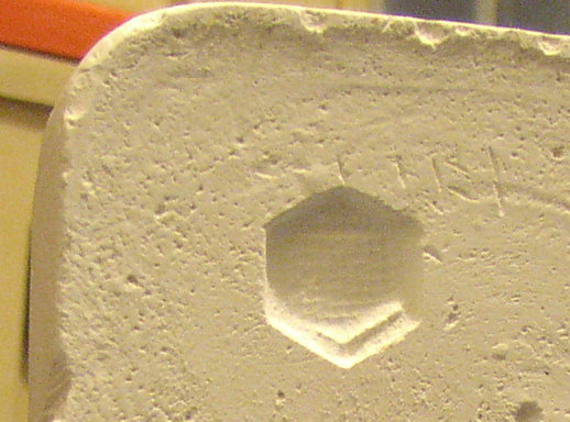
Throw on a block of plaster of paris, and you can easily cut out molds:
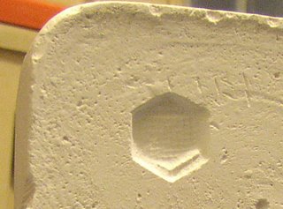
It would be easy to add sprue-points and gates to lock positions, then you could make a double-sided mold that accurately lines up.
Pouring in something simple like molten aluminium could produce some nice metal parts.
Of course it's not the reprap way, but it's interesting nonetheless.
Plug a dremel onto the extruder stage, and suddenly you have a mini-mill.
Throw on a block of plaster of paris, and you can easily cut out molds:
It would be easy to add sprue-points and gates to lock positions, then you could make a double-sided mold that accurately lines up.
Pouring in something simple like molten aluminium could produce some nice metal parts.
Of course it's not the reprap way, but it's interesting nonetheless.
Comments:
<< Home
S,
this seems 'well worth' saying, I think that one of RepRap's big potentials is 'it' as a kind of tool making machine.
Casting, as an idea, is one that I've not looked @ much since I was a student.. stuff like this makes me go 'look it up' again!
K
this seems 'well worth' saying, I think that one of RepRap's big potentials is 'it' as a kind of tool making machine.
Casting, as an idea, is one that I've not looked @ much since I was a student.. stuff like this makes me go 'look it up' again!
K

***Of course it's not the reprap way, but it's interesting nonetheless.***
LOL! I think now has two ways. Absent a grinder and filament maker that you can use in your shop casting is the perfect thing to do with CAPA scrap. It's also a good method for larger, simple parts which you intend to make a bunch of. :-)
LOL! I think now has two ways. Absent a grinder and filament maker that you can use in your shop casting is the perfect thing to do with CAPA scrap. It's also a good method for larger, simple parts which you intend to make a bunch of. :-)
This is precisely what I was thinking about - we know there are quite a few things RepRap extruders won't do, like metalworking. And unless you can work with metals, there are a lot of things you can't do.
Ergo, two things spring to mind - interchangeable toolheads, and using the RepRap to do something you can then do something else to.
Casting gives it the capability to make its own metal parts, and also to make products that require metals. Cool.
Ergo, two things spring to mind - interchangeable toolheads, and using the RepRap to do something you can then do something else to.
Casting gives it the capability to make its own metal parts, and also to make products that require metals. Cool.
*A few points - normal plaster isn't refractory enough to take molten aluminum; pewter yes, but nothing hotter. You would want to use jeweler's investment or something.
*For molding, I would just print out the plastic object, invest it with plaster, and melt out the plastic.
*I think it would be cool to do subtractive fabrication with a RepRap, even if it means some difficult design work. When you're doing additive and subtractive Rapid Prototyping it's called:
shape depostition manufacturing
(I'm having trouble pasting in a link to a google search, but you guys know how to surf the web.)
Often they're also doing pick-and-place inlay of prefabricated components.
*This is why I'm happy I'm using my Taig Mill as a RepStrap. It's a scanner*! It's a CNC Mill**! It's a 3D printer***! And it only costs USD$1.2K with shipping!
(* Someday, maybe.)
(** Real soon now.)
(*** Somewhat soon now.)
It strikes me as possible to have a second generation design for doing heavy work with perhaps even cast iron axes made using FDMed molds. Perhaps then use some plastic jigs and grinding elements to put a finish on the iron axis parts. Use those, and you've probably got a sturdy enough set of axes to machine metal; use software compensation to deal with imperfections as well as you can, and go from there... The actual casting is doable without tremendously sophistocated tools; I know I've hit about a hundred degrees K below what's needed for cast iron before with a pile of bricks, an electric blower, and a bag of charcoal... (melted copper at 1357 K; cast iron is right around 1450.)
Well, if we want to make stronger and more rigid elements, rather than doing traditional metalcasting, I like the idea of printing the object as a slurry of powdered metal or ceramic particles suspended in a gel or slip and then firing it in a furnace.
I guess it depends on your tooling and workshop. If you're set up to cast metal, you do it one way, and if you have a furnace, you do it the other way.
The one nice thing about creating a fireable object is that you can do it with a normal, low-stiffness RepRap built from thermoplastic.
It looks inevitable that eventually we're going to have multiple versions of postioning system, and multiple heads.
Touch-probe head, scanning heads, extruder heads, machining heads, laser cutting/laser sintering heads, pick-and-place heads, etc.
Most interesting indeed, especially since I'm on the verge of the first full scale test of my foundry!
On the subject of suitable casting materials, could one perhaps build some kind of syringe/archimedian screw to directly extrude green sand?
Some articles on the web (including wikipedia) suggest a plaster cast will work as a one-time mold for metals including aluminium, zinc and copper, but not really iron.
The high temperatures degrade the plaster and it has to be broken off.
An even higher temperature mold (still one-time) can be made from a mixture of plaster of paris and silica sand.
The high temperatures degrade the plaster and it has to be broken off.
An even higher temperature mold (still one-time) can be made from a mixture of plaster of paris and silica sand.
"normal plaster isn't refractory enough to take molten aluminum"
I agree with Simon. I've seen plaster of Paris used to cast a eutectic Al/Si alloy (like engine blocks are made of, IIRC), even though I'm pretty sure it decomposes at the melting point of pure aluminum.
Rather than a lost-wax investment, the method of polymer-to-refractory transition that I saw firsthand was to make two elastomeric polyurethane half-mold positives, which are are durable enough to cast several plaster molds from each one. The PU had enough give to allow it to pull free, with the right mold release agent.
The positive halves can be reprapped onto a smooth, flat surface which bonds permanently to the polymer.
If the peristaltic pump allows printing of silicone, or if a thermoplastic elastomer (e.g., hot glue) is used in the current extruder head, you could reprap once, then have a permanent master for a large number of Al castings.
Also worth noting: silicone, with the proper heat treatment, is refractory enough to cast pewter and IIRC some low-melt bronzes.
PS:
I'd also like to see what kind of casting can be done with pikrete (frozen paper slurry). If you're willing to run your reprap in a chest-style freezer, and can make the mold porous enough to allow steam to escape, you might be able to cast white cast iron without much change to the extrusion head. You would just need an insulated slurry reservoir, an insulated/heated supply tube, and a thickener (gelatin, starch, agar, PEG...) to prevent fiber settling and drips.
The whole freezer thing would, of course, be unnecessary for certain combinations of season and lattitude.
Also:
The half-positive trick also works for green sand, it just needs some slope to each wall, whereas plaster can basically do a vertical surface...even undercutting if the elastomer is just a "skin" on a removable, rigid support.
So as I see it, the biggest barrier to reprapped white cast iron rails will be the casting process itself.
What would be very useful is to cut molds for small gear blanks and then design a reprappable tooth cutter that could make the teeth.
You could use the molds to make the gears from scrap.
One thing that you notice very quickly is that when you put more than a hundred teeth on a gear the sides of the gear go very nearly straight, rather like a rack gear.
You could use the molds to make the gears from scrap.
One thing that you notice very quickly is that when you put more than a hundred teeth on a gear the sides of the gear go very nearly straight, rather like a rack gear.
***What would be very useful is to cut molds for small gear blanks and then design a reprappable tooth cutter that could make the teeth.***
Perhaps after reprap 1.0, it would be good to view the reprap as a 'solution' rather than a single machine... While we've got the basic extruder for most of the functionality, we're slowly creating new devices/addons that we 'need' for the whole solution... Perhaps in reprap 2.0 you've got the reprap extruder, the reprap spooler (to make the spools of material), the reprap 'subtractive' (for drilling/dremelling/etc), the reprap gearcutter, maybe even a reprap forge or something (mill out the mold then fill it). If the reprap is going to be capable of reproducing itself, then all the tools/technologies that go into making it need to be incorporated into it... We've got a network for controlling multiple machines, lets use it... There should be a reserved 'pool' of addressess for the new modules, and someone/group/etc should be in charge of assigning those to new modules that are appropriate...
So no... if you've got gears in your reprap... you wouldn't create a reprappable tooth cutter... you'd create a reprap tooth cutting module (which would inherently be reprappable). Or rather... someone would create a reprap tooth cutting module, and you'd just incorporate it into your overall design...
Plaas: You read my mind. I was thinking of gear cutters too. I think we are going to have difficulty ever making really good gears additively. But at the same time, I think we should do as much as possible additively. Subtraction is a very messy business.
lord_cat: I couldn't agree more, and that is really fundamental to the goals of reprap. That is why the system is designed to be modularly expandable. We didn't put a network on there with the expectation of having only 4 modules :)
There are lots of cool modules you can imagine adding, such as plastic production, self-assembly, etc.
Reprap is the entire system, not just the printer core. And that entire system can replicate.
Speaking of gear cutting, about a year ago I saw a diagram of an "old-fashioned" gear cutting machine. It used some geometric tricks to cause a cutting wheel to move in a perfect involute shape.
In this modern age that's considered too complex and gears are just cut with gear hobs and so on, but these in turn also need to be made by a special machine. The advantage of the old school method over this is that you didn't need special cutters.
I have to wonder if the old fashioned way is a better way to do it for reprap technology.
Sadly, I've spent the last six months on and off looking for it again, and I can't find a trace.
Does anybody have a reference to the old way of doing such things?
Another way might be to just move the x/y axis to produce the involute pattern. The z axis could instead be hooked up to rotate the gear blank and the extruder would be replaced with a spinning cutting wheel. This probably isn't as accurate as using a geometric method though.
Re gear cutting, I've got a very old textbook lying about that might help - while I don't think it explicitly describes such a machine, I think it does describe how to generate involute profiles using linkages and geometric tricks - I'll have a leaf through it and post anything I find.
Well, the book wasn't a whole lot of good, but I did find this web page:
http://www.pathcom.com/~u1068740/gears.html
There are a couple of animations on there showing how to generate both involute and cycloidal gear profiles - I think the involute profile of each tooth could be made using a cutting bit mounted on the end of a fine-toothed straight rack caused to rotate, planetary-gear style, around a pinion with diameter equal to that of the generating circle mounted on the same axis as the workpiece centre, as in the cyan animated gif.
Post a Comment
http://www.pathcom.com/~u1068740/gears.html
There are a couple of animations on there showing how to generate both involute and cycloidal gear profiles - I think the involute profile of each tooth could be made using a cutting bit mounted on the end of a fine-toothed straight rack caused to rotate, planetary-gear style, around a pinion with diameter equal to that of the generating circle mounted on the same axis as the workpiece centre, as in the cyan animated gif.
<< Home
![]()