Tuesday, October 17, 2006
Rethinking the Mk II heater nozzle...
We know the Mk II works. It has been the major breakthrough that makes the rest of RepRap possible.
I'm currently making a serious effort to get a Mk II going. As usual I can't ever seem to leave well-enough alone, though. :-(
The heater nozzle assembly of the Mk II has always been the most fraught for me.
It has always struck me that for something that is supposed to be made in the wilds of Africa that part of the assembly seems remarkably sophisticated.
First off, you really need a lathe to make the brass heater nozzle. You might as well need a lathe to run a straight hole through several inches of PTFE rod.
 I've tried it a number of times both freehand and with a drill press with a cross slide vise. I finally had to drill a hole in a block of wood and slide the PTFE rod into that to even hope to get the job done properly. It's a real pain for a retard like me.
One thing that bothers me about that heater nozzle, aside from the fact that it's a bugger to make, is that it has a lot of material in it and as a result has a considerable time constant.
As designed by Adrian the thing has just over a cubic centimetre of brass in it.
Depending on the brass you use that's about 8.5 grammes.
In order to make it easier to unjam Vik has added a nut onto the end of it. That's handy but it adds more mass onto the nozzle and thus increases the time constant.
That seems to have become the standard heater nozzle design for right now. Here's a neat one done by TylerM.
Okay, so we have a way to do it. Problem with the one we have is that it seems to be a fairly finicky thing to make. You also need to screw it into that PTFE rod.
In practice Vik has discovered that he has to periodically park the extruder and also needs to keep a fan on it to make it work right.
I got to wondering if you couldn't somehow make one somewhat more easily. This evening I took a shot at doing a mockup of one that I could make in the wilds of Africa if I needed to.
I've been eyeing some 5/32" hard copper tube in the hardware for some weeks. A foot of it costs US$0.75. This afternoon I took my micrometer and a piece of the CAPA filament that Jim sent along to see if would fit.
Sure enough the CAPA filament fit wonderfully into the hard copper tube. The inside diameter is spot on at 3.05 mm. Unlike the ones we are making now, however, the wall thickness of this premade tube is only 0.47 mm instead of 1.5 mm in the original lathe-made heater nozzle.
The whole diameter of this 3 mm ID tube is only about 3.94 mm. An equivalent length of this stuff weighs only 2.54 grammes as opposed to just at 8.5 for the original design. That's about 70% lighter than the original design and the good Lord only knows how much lighter than the one that has a nut on the end.
I had some 25x25 mm PTFE block lying around from some earlier work with the auger bit extruder I designed months ago. I had bought it to give strength to the 1/2 inch rod that I used to separate the auger pump from the heater barrel. I'd discovered that when you pressurize PTFE when it's hot it bulges.
It struck me that that 25x25 mm cross section bar would be a heck of a lot easier to seat in a cross-slide vice on a drill press. As well, you could bolt it to the bottom of the Mk II's polymer pump instead of using that friction grip that Vik had noted tended to slip when you overpressured.
So, here's what I did. I didn't want to screw or friction fit the copper tube into the PTFE. I made a flaring mandrel out of a piece of scrap steel by drilling a 5/32 inch hole in it then countersinking a 1/4 inch hole into it to make a flaring die.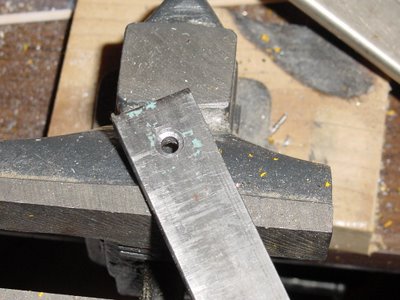
Once I'd made that I cut a 55 mm piece of the tube.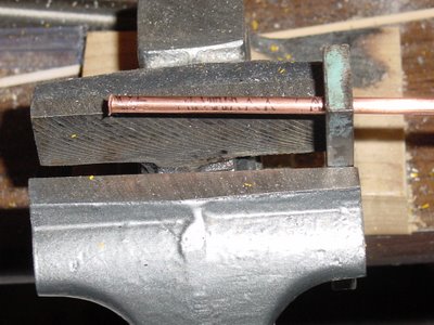
The die serves as a good way of gripping the tubing while you use a hacksaw on it.
I then used the 5/32 inch drill bit run backwards to create a lip on the end of the tube.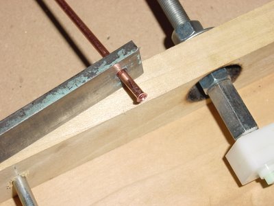
After that I cut a square washer for the flared nozzle out of 0.7 mm copper sheet (the kind you engrave stuff on for trophies or discreet business signs by office doors.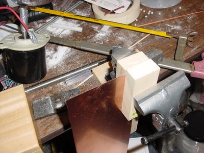 It's good to secure this stuff between two scraps of wood when you saw it so that you don't warp it.
After that you seat the heater nozzle in the washer. I set out to buy a 0.5 mm drill bit but was only able to get a 1 mm drill bit, so I used it for this exercise. What i did instead of drilling with it was to use it to form the extrusion orifice when I crushed the end of the copper tube down on the drill bit.
Afterwards I realised that any steel wire of the proper diameter would have done the job just as well.
I touched up the nozzle with my Dremel tool.
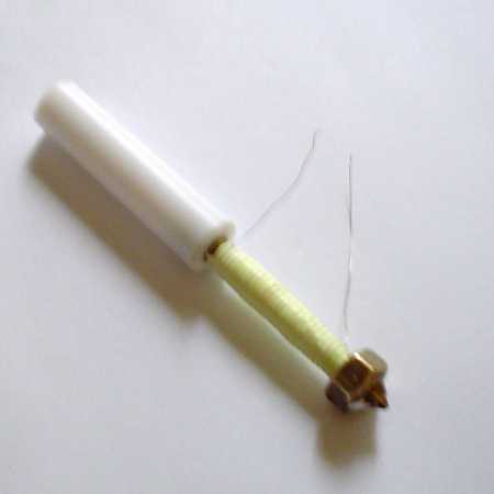
I was then ready to saw off a piece of 25x25 PTFE bar and drill it to seat the heater nozzle.
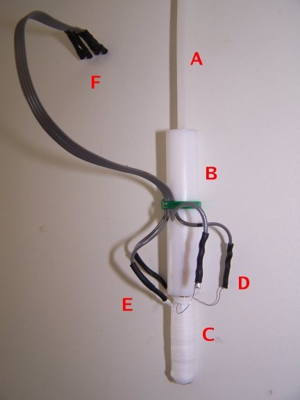
What you wind up with is quite a robust heater nozzle assembly.
Here you see it with a piece of CAPA filament fed into it.
You then make your PTFE filament guide and thermal barrier out of a 50 mm piece of 25x25 mm bar stock and drill the 3 mm hole through it's centre. You can then secure the heater nozzle assembly to the thermal barrier by drilling a hole at each corner of the bar stock and securing it to the polymer pump assembly with something like M3 studding and lock washers and nuts.
What I'm hoping I have here is a heater barrel and nozzle that is easier to make that can handle higher temperatures and heater barrel pressures so that we can try some other polymers like PLA, HDPE and polypropylene. With a little luck the smaller thermal time constant for the heater head will make it more quickly responsive to energy input changes and reduce the need for setting it aside occasionally.
I'm currently making a serious effort to get a Mk II going. As usual I can't ever seem to leave well-enough alone, though. :-(
The heater nozzle assembly of the Mk II has always been the most fraught for me.
It has always struck me that for something that is supposed to be made in the wilds of Africa that part of the assembly seems remarkably sophisticated.
First off, you really need a lathe to make the brass heater nozzle.
 You might as well need a lathe to run a straight hole through several inches of PTFE rod.
 I've tried it a number of times both freehand and with a drill press with a cross slide vise. I finally had to drill a hole in a block of wood and slide the PTFE rod into that to even hope to get the job done properly. It's a real pain for a retard like me.
One thing that bothers me about that heater nozzle, aside from the fact that it's a bugger to make, is that it has a lot of material in it and as a result has a considerable time constant.
As designed by Adrian the thing has just over a cubic centimetre of brass in it.
Depending on the brass you use that's about 8.5 grammes.
In order to make it easier to unjam Vik has added a nut onto the end of it.
 That's handy but it adds more mass onto the nozzle and thus increases the time constant.
That seems to have become the standard heater nozzle design for right now. Here's a neat one done by TylerM.
Okay, so we have a way to do it. Problem with the one we have is that it seems to be a fairly finicky thing to make. You also need to screw it into that PTFE rod.
In practice Vik has discovered that he has to periodically park the extruder and also needs to keep a fan on it to make it work right.
I got to wondering if you couldn't somehow make one somewhat more easily. This evening I took a shot at doing a mockup of one that I could make in the wilds of Africa if I needed to.
I've been eyeing some 5/32" hard copper tube in the hardware for some weeks. A foot of it costs US$0.75. This afternoon I took my micrometer and a piece of the CAPA filament that Jim sent along to see if would fit.
Sure enough the CAPA filament fit wonderfully into the hard copper tube. The inside diameter is spot on at 3.05 mm. Unlike the ones we are making now, however, the wall thickness of this premade tube is only 0.47 mm instead of 1.5 mm in the original lathe-made heater nozzle.
The whole diameter of this 3 mm ID tube is only about 3.94 mm. An equivalent length of this stuff weighs only 2.54 grammes as opposed to just at 8.5 for the original design. That's about 70% lighter than the original design and the good Lord only knows how much lighter than the one that has a nut on the end.
I had some 25x25 mm PTFE block lying around from some earlier work with the auger bit extruder I designed months ago. I had bought it to give strength to the 1/2 inch rod that I used to separate the auger pump from the heater barrel. I'd discovered that when you pressurize PTFE when it's hot it bulges.
It struck me that that 25x25 mm cross section bar would be a heck of a lot easier to seat in a cross-slide vice on a drill press. As well, you could bolt it to the bottom of the Mk II's polymer pump instead of using that friction grip that Vik had noted tended to slip when you overpressured.
So, here's what I did. I didn't want to screw or friction fit the copper tube into the PTFE. I made a flaring mandrel out of a piece of scrap steel by drilling a 5/32 inch hole in it then countersinking a 1/4 inch hole into it to make a flaring die.

Once I'd made that I cut a 55 mm piece of the tube.

The die serves as a good way of gripping the tubing while you use a hacksaw on it.
I then used the 5/32 inch drill bit run backwards to create a lip on the end of the tube.

After that I cut a square washer for the flared nozzle out of 0.7 mm copper sheet (the kind you engrave stuff on for trophies or discreet business signs by office doors.
 It's good to secure this stuff between two scraps of wood when you saw it so that you don't warp it.
After that you seat the heater nozzle in the washer.
 I set out to buy a 0.5 mm drill bit but was only able to get a 1 mm drill bit, so I used it for this exercise. What i did instead of drilling with it was to use it to form the extrusion orifice when I crushed the end of the copper tube down on the drill bit.
Afterwards I realised that any steel wire of the proper diameter would have done the job just as well.
I touched up the nozzle with my Dremel tool.
I was then ready to saw off a piece of 25x25 PTFE bar and drill it to seat the heater nozzle.
What you wind up with is quite a robust heater nozzle assembly.

Here you see it with a piece of CAPA filament fed into it.

You then make your PTFE filament guide and thermal barrier out of a 50 mm piece of 25x25 mm bar stock and drill the 3 mm hole through it's centre. You can then secure the heater nozzle assembly to the thermal barrier by drilling a hole at each corner of the bar stock and securing it to the polymer pump assembly with something like M3 studding and lock washers and nuts.
What I'm hoping I have here is a heater barrel and nozzle that is easier to make that can handle higher temperatures and heater barrel pressures so that we can try some other polymers like PLA, HDPE and polypropylene. With a little luck the smaller thermal time constant for the heater head will make it more quickly responsive to energy input changes and reduce the need for setting it aside occasionally.
Comments:
<< Home
I've been putting off trying to make a MKII, because of its complexity and my lack of proper tools, but this looks like something I could knock off in an afternoon!
One thing that concerns me is the extrusion orifice... would enough pressure from the extruder itself cause the nozel to deform/uncrush? how much force does it take to 'bend' the metal there?
Alternativley, I wonder if you could get a speed improvement on larger parts/areas with a wider/slit nozel instead of simply increasing the size of the hole.

***One thing that concerns me is the extrusion orifice... would enough pressure from the extruder itself cause the nozel to deform/uncrush?***
That concerns me, too. I'll let you know how that works out.
***how much force does it take to 'bend' the metal there?***
I put it a vise and crushed it.
That concerns me, too. I'll let you know how that works out.
***how much force does it take to 'bend' the metal there?***
I put it a vise and crushed it.
BTW, once I had the parts to do the job it took me about 30 minutes to make it.
I spent several hours documenting what I did on the blog. :-p
I spent several hours documenting what I did on the blog. :-p
It is possible though that the increased thermal mass in the existing design smooths out temperature variations - that's where my guess takes me anyway. It'll be interesting to see how things pan out.
Vik :v)
Vik :v)
How much thermal mass is there in the existing design?
How much of the heat is held by the plastic compared to the metal itself (I would guess the plastic has most of the heat once it gets up to temperature)
It seems like your (Vic's) cement nozzle design would by far be the better solution if higher thermal mass is a good thing. It also seems such a solution would easily adapt to the copper pipe designs.
***How much of the heat is held by the plastic compared to the metal itself (I would guess the plastic has most of the heat once it gets up to temperature)***
Let's see. If I haven't dropped a decimal somewhere we have something just under 0.4 grammes of CAPA in the extruder barrel and 8.5 grammes of brass in the barrel itself. Figuring that the specific heat of metals tends to be about a tenth of that of organic materials it would appear that the energy inventory in the CAPA would be about half of the inventory of energy in the barrel.
The design I'm working on runs about 2.5 grammes so the barrel would have about half of the energy inventory of the CAPA in that case.
Of course, if you wrap the whole show up in something heavy there is no point in trying to make the barrel itself as light as possible.
"What if we used 'plastic on an spray can'."
How do we recycle the product? how do we create it ourselves? how expensive is 'plastic on a spray can'? A big thing, to me at least, for the RepRap is its ability to recycle the items it creates (it's still more theory than practice at the moment, but it's certainly viable).
How do we recycle the product? how do we create it ourselves? how expensive is 'plastic on a spray can'? A big thing, to me at least, for the RepRap is its ability to recycle the items it creates (it's still more theory than practice at the moment, but it's certainly viable).
Yeah, don't fancy spraying around solvents much.
As to the cement model, it goes wrong the moment any plastic is deposited inside the cement body. Some non-conducting liner is needed.
Vik :v)
As to the cement model, it goes wrong the moment any plastic is deposited inside the cement body. Some non-conducting liner is needed.
Vik :v)
The flaring mandrel was a great idea.
I wonder if you might drill a blind 5/32 inch hole right next to your through hole, and maybe put a 0.5mm hole in the bottom once you get the properly-sized bit. You can then put a short length of filement into a fresh piece of tube to keep the drill chuck from crushing it, leave the stub end of the bit where the nozzle will ultimately be, and create your nozzle with a mandrel, too.
I'm guessing that would be both stronger and more precise than the crimping method.
The bottom hole wouldn't have to be as small as 0.5 mm. Only the wire would be. That would crimp the nozzle rather like a .22 caliber blank cartridge. I wonder, though, if you'd get a clean orifice that way. It's worth a try.
If I could use a 3 mm rod within the copper barrel to keep it from crumpling that would probably cut down the care with which you had to do the crimping.
Post a Comment
If I could use a 3 mm rod within the copper barrel to keep it from crumpling that would probably cut down the care with which you had to do the crimping.
<< Home
![]()