Monday, October 30, 2006
More thoughts on the Mk II...
I've been thinking some more about the Mk II. It's a great machine, but it's a little difficult for somebody with limited skills and tools to make up a few of the parts that aren't polymer.
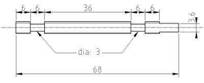
After the nozzle, the threaded polymer pump is the biggest bother. The bushings are inset from the ends of the studding which means that you have to have split bushings, which are also a pest to make.

What would happen if you placed a bushing that seated at the lower end of the studding, which you'd turn down and another that slipped over the upper end as a sleeve. If you did that you could prepare the studding polymer pump in an ordinary electric drill with a metal file. You'd only have one threaded length instead of three, which would make seating bushings a lot easier.
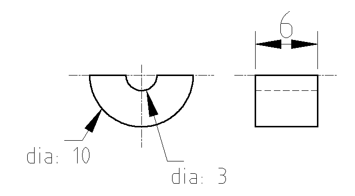
As well, you could make the bushings out of square bar stock, probably brass. That you could secure in an ordinary vise with ease and drill with a hand-held electric drill or drill press if you had it and then saw the bushings off the bar after you'd drilled them.
It would also be nice if we shifted the drive motor over to a GM3 which has a short stub shaft coming out of the top of the gear box. That would let us install an AS5035 chip on top of the drive shaft and monitor filament feed rates and detect jams in real-time.
That takes me back to Vik's original drawing.
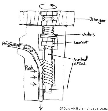 Note how Vik feeds the filament in from the side. I've wondered what is to stop us from making the pumped filament exit the pump along a radius, too. That would let us avoid the bottom bushing with the emerging filament. It would also let us put the polymer pump at a 90 degree angle or some other angle to the line of the extruder barrel. That would let us reduce the height of the overall assembly of the Mk II and make our overall machine a bit more compact and maybe use less material in the structure of the reprap.
Comments? Ideas? Rotten tomatoes? :-D

After the nozzle, the threaded polymer pump is the biggest bother. The bushings are inset from the ends of the studding which means that you have to have split bushings, which are also a pest to make.
What would happen if you placed a bushing that seated at the lower end of the studding, which you'd turn down and another that slipped over the upper end as a sleeve. If you did that you could prepare the studding polymer pump in an ordinary electric drill with a metal file. You'd only have one threaded length instead of three, which would make seating bushings a lot easier.
As well, you could make the bushings out of square bar stock, probably brass. That you could secure in an ordinary vise with ease and drill with a hand-held electric drill or drill press if you had it and then saw the bushings off the bar after you'd drilled them.
It would also be nice if we shifted the drive motor over to a GM3 which has a short stub shaft coming out of the top of the gear box. That would let us install an AS5035 chip on top of the drive shaft and monitor filament feed rates and detect jams in real-time.
That takes me back to Vik's original drawing.
 Note how Vik feeds the filament in from the side. I've wondered what is to stop us from making the pumped filament exit the pump along a radius, too. That would let us avoid the bottom bushing with the emerging filament. It would also let us put the polymer pump at a 90 degree angle or some other angle to the line of the extruder barrel. That would let us reduce the height of the overall assembly of the Mk II and make our overall machine a bit more compact and maybe use less material in the structure of the reprap.
Comments? Ideas? Rotten tomatoes? :-D
Comments:
<< Home
My thoughts are this:
Yes, that may be a better improvement to the design. However, the current design is tried and true. It works.
Since we are now shifting to getting v1.0 out the door, I would say that if it works, dont change it. Those parts are really easy, and all it takes is one person spending an afternoon to make all of them for our small team.
Now, once we do get v1.0 out and everyone has one, then we can start focusing on improvements. You can do that change, and if it is indeed better and easier, then we'll roll it back into the main project.

Admitadly, my MkII is in pretty sad shape and may never work right, but I think I did the split-bushings pretty well on there, and with minimal machinery. I simply went with the 1/2 washer method and built them up with 4-6 washer halves; and they seem to work just fine... (the crudley formed polymer clay that I used to make the bootstrap pieces with, on the other hand, may very well be its downfall) If I were to move to your design (bushings on the ends instead of inset) I would probably stick with washers and just glue a stack of them together for each end... Beyond that, I'd probably move to a 'store bought' bushing or bearing to put into it... I don't think I'd want to go through the trouble of obtaining, and drilling, some square brass barstock, and then slicing it up...
If we're worried about putting enough pressure into the feedstock to properly extrude through a small enough nozel, you're going to want to go straight from the threaded rod, and not curve it away. Any curvature deflects some of the force away from the 'forward' movement towards the sides, and makes it harder to extrude. I don't know how much of an issue that is with the MkII, but I know it was an issue with the filament extruder.
Personaly, I've liked the idea of replacing the threaded rod with a set of gears. A gear on either side with, say, 2.6mm of space in between them, turning in oposite directions. *|* (* = gear, | = feedstock). Attach slightly bigger gears to the axis of each of those so the bigger ones touch/drive eachother, and you just attach the motor to one of them, letting it drive both. That way you've got the motor off to the 'back', and the height is just a little bigger than the size of the larger gears (sitting side by side). You could float one of the axis with a spring on it, and compensate in the tooth design on the bigger gears, to give it a little play for missized feedstock. I don't need to craft any fancy shapes for something like this either; two pieces of plexiglass/etc with the gears sandwiched inbetween, the motor attached to the back, and something to attach to the nozel.
***Since we are now shifting to getting v1.0 out the door, I would say that if it works, dont change it.***
If we're talking about mixing ideas from both Arnie and Zaphod, we're talking about a major design iteration, not just getting it out the door, I think. Arnie parts need support material, too, unless they're completely redesigned.
If we've got the manpower, it might be worth taking another look at Mk II. We can always fall back on it if the "improvements" don't do what we want.
***Personaly, I've liked the idea of replacing the threaded rod with a set of gears.***
That was the Mk I. According to Adrian, it didn't work very well.
***That was the Mk I. According to Adrian, it didn't work very well.***
Then it's settled... I'm building my repstrap version of the Mk I once I get all three axis moving at once! (and I find a good supply of gears that I can browse by hand...)
Then it's settled... I'm building my repstrap version of the Mk I once I get all three axis moving at once! (and I find a good supply of gears that I can browse by hand...)
Whew! I really would have a chat with Adrian before you make the time committment. If you insist, however, here is his more or less complete link to the device.
http://reprap.org/Downloads/extruder/extruder.html
http://reprap.org/Downloads/extruder/extruder.html
I think I'll pass for the moment... That design is definatley a lot more complex than what I'm planning, and doesn't really fit the true 'spirit' of what I'm getting at...
I don't plan on making nearly that sort of time investment; I'll spend more time shopping for gears than I will making the thing... and then I'll spend even more time working on getting something to test it with! Making the thing will be a good 15 minute distraction somewhere in the middle of all that :)
I don't plan on making nearly that sort of time investment; I'll spend more time shopping for gears than I will making the thing... and then I'll spend even more time working on getting something to test it with! Making the thing will be a good 15 minute distraction somewhere in the middle of all that :)
I tried a more direct approach, using gears with pins in for extra grip. The problem is that the plastic is soft enough for point contact to rip through. A screw rod delivers 3 benefits over gears simultaneously:
1. lots of grip
2. a mechanical advantage
3. ratcheting
Unless you drive your gears with a worm, you'll be hard pressed to match that. As a worm is basically a short piece of threaded rod, why not just use one in the first place?
Vik :v)
1. lots of grip
2. a mechanical advantage
3. ratcheting
Unless you drive your gears with a worm, you'll be hard pressed to match that. As a worm is basically a short piece of threaded rod, why not just use one in the first place?
Vik :v)
If the gears cause too much damage, I can replace them with 'wheels' of some kind... I'm loosley basing this off a pasta machine or meat grinder, only with a much smaller inlet and without the specific intention of shreading/reforming the rod while pulling it through...
The Mk II is nice and all, but I don't see it being that practical as a repstrap... I may have missed it, but I haven't seen anyone else's attempts at a repstrap version of it, and aside from mine already partialy breaking while trying to assemble it (broke off the 'after thought screw holes' I attached to it), I have serious doubts that mine is accurate enough to even work right...
If I can build an easily repstrappable extruder mechanism that will limp along long enough to prototype the pieces for a Mk II, then I've accomplished my goal...
If, along the way, I can create an extruder mechanism that works as about as good as, or even better than, the Mk II, then that's a bonus... There's a lot of material out there that's got the potential to be extruded... the Mk II can't be the best choice for all of them!
But unless you've got some technique for easily repstrapping the Mk II, that's where I'm at... (and no, having someone build one for me is not an option i'll accept!)
Hand-mould from Polymorph?
Seriously. Jig the parts in place and use hot polymer to hold it together.
Vik :v)
Seriously. Jig the parts in place and use hot polymer to hold it together.
Vik :v)
Just a comment about gear driven extrusion. I've only been able to come up with one idea that seems like it might work. That is to curve the polymorph filament -around- the gear that would drive it, for much more contact area. Maybe 120 degrees for example. The outer edge of the filament could be pressed against the gear with a curved groove of smooth material.
-Maybe- it could work, not very sure!
As for threaded rods and tangents, I've puzzled over that too. I think the trick might be in the shape and accuracy of the groove or channel used to hold the filament against the threaded rod.
In the end, I moved away from all of those ideas. I think something very different is needed...
A comment on the idea of turning the filament through an angle between the forcing mechanism and the heated tube: this is the point in the whole system where the maximum forces are generated; I think we'd need a very strong reason indeed not to keep the whole thing in line. Euler buckling on the filament is bound to be a problem if you force it round a corner, no matter how hard you constrain it.
Incidentally, the problem I hade with several pinch-wheel forcer designs was that CAPA is very slippery...
Incidentally, the problem I hade with several pinch-wheel forcer designs was that CAPA is very slippery...
I was actually quite keen on the idea of threading the stock and then using an arrangement that spun a nut at the top of the extruder. Speaking of which, did that produce forces similar to the ones the MKII produces or did the threads fail first? As for something to cut the threads, especially on a polymer rod, we could use an RP'ed block, a nut, and several fragments of blade to do that without much issue... perhaps even cut the nut to form the blades on it. We don't need it to cut metal...
Adrian, I agree with you entirely. I didn't know the term, but Euler buckling is what I imagined to be the big problem source. I came close to modeling a tangent aproach like Forrest mentioned, then stopped short because I suspect any gear or threaded rod driven extruders are going to be very limited in performance. They are all limited by the same factors.
Something like pressurized chambers or "dry" fine filament extruders (melt happening after the nozzle) will have to be dreamed up for MkIII.
Only a radically different and more accurate MkIII head will allow the RepRap project to build "real" stuff. I think the MkII head is perfect for, but limited to, the proof of concept phase RepRap is in now.
***Euler buckling on the filament is bound to be a problem if you force it round a corner, no matter how hard you constrain it.***
Given how flexible the filament is I'd have thought we'd have had Euler buckling even if we tried to move it in a straight line.
Given how flexible the filament is I'd have thought we'd have had Euler buckling even if we tried to move it in a straight line.
My impression on the buckling is it is one of the big limits, and if there is an added curve in the filament the buckling will be much more severe. Isn't it an exponential progression?
The further from a straight line it is, the greater the lateral force...? And by far? I know it can't be a linear progression.
Post a Comment
The further from a straight line it is, the greater the lateral force...? And by far? I know it can't be a linear progression.
<< Home
![]()