Saturday, August 05, 2006
Time to try another approach...
That little glitch in the slicing and dicing software turned out to be a very big glitch, a conceptual glitch, in fact. Turns out that the insetting method that I was using to create the perimeter path for the Mk II has a real hassle. You can see it here.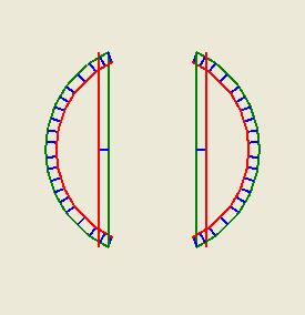
The green line segments represent a slice across the bead and the red lines represents the attempt to inset them. It turns out that if you have a straight line meeting a curved line at an acute angle you can get some real problems with overlaps where the overlap can mean that several curved line segments can protrude beyone your straight line. That makes my little clip or extend routine more than a bit problematic.
Right off hand I can't see a way to fix that which doesn't involve me checking every inset line to see if it intersects with another inset line. That's just about an n^2 calculation problem which is a terrible thing to have in your code.
I'm half-tempted to go on and steal Adrian's grid approach and salvage the rest of my routines to work with that. I'm going to think about this for a few more hours before I do that, though. Maybe I'll think of something sneaky. :-)
Comments:
<< Home
Can you define the area within the red lines? Like to just fill it with a color for example? Then you could discard the red lines themselves, and re-trace your perimeter once again, but this time it would be the right size, and wouldn't generate little bits that need to be trimmed off.
Just an idea...
Just an idea...

Given two lines joined at point A, construct line AC such that it is an angle bisector.
Then solve for point D such that D is the distance you want from either line. Connect these 'D' points from each vertex together, using the same connection network in the original lines.
Should be easy, given what you've accomplished already.
Then solve for point D such that D is the distance you want from either line. Connect these 'D' points from each vertex together, using the same connection network in the original lines.
Should be easy, given what you've accomplished already.
I'm going to take a crack at the grid approach first. I'll be able to reuse about 90% of the coding I've already written.
I know you've already started on your grid method, but if you've still got the code for exact lines, I ran thru the algebra and trig to calculate the inset lines (Using PDL code), and assuming you have a 2D point math class/library.
FUNCTION GetInset( Point A, Point B, Point C, float insetAmount )
-- Transform the segments so the point in common is at the origin.
Let Point dAB = A - B
Let Point dCB = C - B
-- Get the unit vectors for the two line segments.
Let Point U = dAB / Length( dAB )
Let Point V = dCB / Length( dCB )
-- Calculate a point on the angle bisector
Let Point MP = ( U + V ) / 2
-- .. and turn it into a unit vector.
Let Point M = MP / Length( MP )
-- Calculate the sin of the angle for the angle bisector, using the cross product calculation
Let float sin_bisector = M.X * V.Y - M.Y * V.X
-- Calculate the length along the angle bisector to get the desired inset from the two line segments
Let float t = insetAmount / sin_bisector
-- Calculate the actual point, by extending the M unit vector out, and adding the original B point to offset it back from the origin.
Let Point P = B + t * M
-- P is the point we are looking for.
Return P
Give it a try.. hopefully, I translated the logic addequately enough. I wrote a quick C# program to make sure I got everything right, and it appears to work great.
Oh, the input points are 3 points defining two line segments, with point B in common.
Also, there are pathelogical cases when the lines approach being colinear. Logic would be needed to handle these situations.
Post a Comment
Also, there are pathelogical cases when the lines approach being colinear. Logic would be needed to handle these situations.
<< Home
![]()