Wednesday, July 26, 2006
Frankenboard and Frankenmotor with IR Thermometer...
I finally got the camera back after many adventures and post for your delight a pic of the working PWM Frankenboard and Frankenmotor. I haven't installed the shaft encoder and limits detector at this point.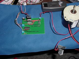
I burned in the board for 20-24 hours before the comms card packed up on Monday night. At the PWM frequency that I'm using the motor will very rarely get out of sync with the pulse train and just stop for no particular reason. That has happened about twice that I've observed. Feedback from the shaft encoder can be used to restart the motor or shut down the PWM signal safely.
That heat sink is really necessary.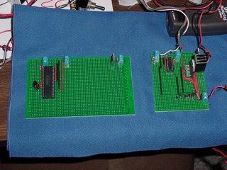
Here's a quick pic of the 16F877A board built out for serial comms.The relative size of the two cpu's is quite astounding. I haven't decided yet whether I want to build this one out as an extruder board or attempt to see if I can drive both the x and z axes (horizontal) with the bigger 16F877A chip.

I burned in the board for 20-24 hours before the comms card packed up on Monday night. At the PWM frequency that I'm using the motor will very rarely get out of sync with the pulse train and just stop for no particular reason. That has happened about twice that I've observed. Feedback from the shaft encoder can be used to restart the motor or shut down the PWM signal safely.
That heat sink is really necessary.

Here's a quick pic of the 16F877A board built out for serial comms.The relative size of the two cpu's is quite astounding. I haven't decided yet whether I want to build this one out as an extruder board or attempt to see if I can drive both the x and z axes (horizontal) with the bigger 16F877A chip.
Comments:
<< Home
Coolness! Glad you got your camera back. :) So how much did those darn heatsinks cost in the end? But they do look nice! ;) I'm guessing they have about 5 square inches of surface total? All at about 1/8th inch thick... I'm trying to find rough rules of thumb for sizing heat sinks cut from my scrap metal pile.
BTW, noted your recommendations for the PIC programmer hard/software...
What do you think went wrong with the comms card?
Ugh, and yeah, that 16F87 is big...
BTW, noted your recommendations for the PIC programmer hard/software...
What do you think went wrong with the comms card?
Ugh, and yeah, that 16F87 is big...

***So how much did those darn heatsinks cost in the end?***
I can't remember exactly. I do remember that it was less than I'd feared. Something between US$0.59 and US$1.29. Those two prices come to mind. I think the US$1.29 is the right one because the little Radio Shack papers of resistors cost US$0.59.
***What do you think went wrong with the comms card?***
I know for sure what went wrong with it. I'm just unsure why it went wrong.
The 100uF capacitor went south. That's what went wrong. The MAX232 chip may have failed, too, but I won't be sure of that till I put another 100uF capacitor back on the board. Hopefully, those will come in from Tahoe today or tomorrow.
***Ugh, and yeah, that 16F87 is big...***
Yes, that's true. That chip washes windows and makes breakfast, though. The two, separate PWM channels are a real treasure that I hope to take advantage of very shortly. The downside is that it doesn't have an internal clock so you have to buy a crystal and some pF range capacitors to go with it (US$0.59 from Randy)
It does run at 20 MHz, though. :-D
***I'm guessing they have about 5 square inches of surface total?***
I measured it to be sure and you're way, way off. The backside that attaches to the chip is 5/8" wide and 1" deep. The four cooling fins are 1/2" deep and 1" tall.
That gives you a total of
(1)(5/8) + (4)(1)(1/2) = 2.625 inches^2 (~1700 mm^2)
The backside is 1/8th inch thick and the fins are about 1/16th inch thick.
Well, I'm looking at the schematic for the comms card, and the 100uF cap(C1). From what I understand of the MAX232 datasheet, that cap is used as part of a charge pump with C3. They also suggest using a 1.0uF cap, not a 100uF.
This clearly tells me... I have no clue about electronics, and I'm way over my head! ;)
I wonder why the clever young fellow who designed the comms card had to replace the small 1uF cap with a bigger one? Does that help to make it more resistant to failure? Maybe he can tell us if an even bigger one might do the trick...
All right, I've said enough silly things for tonight, time for me to go dig under the house...
***They also suggest using a 1.0uF cap, not a 100uF.***
Simon designed the board and I can vaguely remember him saying why he used that 100 uF capacitor at some point, but for the life of me I can't remember why it was that he did it that way. He usually has a very good reason for his design choices.
Simon designed the board and I can vaguely remember him saying why he used that 100 uF capacitor at some point, but for the life of me I can't remember why it was that he did it that way. He usually has a very good reason for his design choices.
I checked with Simon about that 100 uF capacitor. The old, expensive MAX232 chips required one. The newer, generic chips that suit that one require lower ratings, like 1 uF and in one case 0.1 uF. According to Simon you should go with what the data sheet on the particular MAX232 variant that you used suggests.
Post a Comment
<< Home
![]()