Sunday, July 30, 2006
Comms working again...
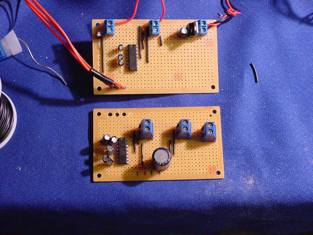
I got my parts consignment at noon today and after discovering that the blown 100 uF capacitor wasn't the only problem that the comms card had I decided to build a new one. The new one is at the top of the pic and the old one is under it. 
As you can see the new card is considerably neater in layout than the old one. Probably the biggest difference was that Randy at Glitchbuster stocks some really short dinky little electrolytic capacitors that take up a lot less room on the board and don't get in the way nearly so much.
I've also stopped trying to use the 5.35v power off of my power supply and have taken to just using regulators to cut 12v down to 5v exactly. I've made that and the serial comms terminals placement on all my boards the same, viz, along the top edge with the 12v supply on the right hand side of the board and the serials comm terminals on the left.
Anyway, I used Simon's diagnostics when I was assembling the board. I then ran a standard serial loop test on it and it fired right up and worked without so much as a hiccough. :-)
I hooked up the Frankenboard and fired up the Frankenmotor with no problems, too. :-D
Comments:
<< Home
Plaasjaapie, Glad to see your new comm card turned out so nicely. I have a ways to go before electronics I build work on the first try!
I've looked up the specs on the L298, seems it dissipates a max of 25 watts. You mentioned that heat sink I was asking you about has 2.5 sqr inches of surface, that 10 watts per sqr inch.
From my limited experience, what I've read so far would seem to say that is very small.
Maybe someone with more experiance can shed more light on that...
Oh yeah, thanks for posting what Simon said about the MAX232.

***I have a ways to go before electronics I build work on the first try!***
I was in the same situation six months ago. I had done a bit of PC interface work back in the early, early 1980's but things had changed so much in the interim that almost none of my experience from that era was of any use. Fortunately, after a lot of hammering the data sheets, playing chimpanzee at the typewriter and trying Simon's patience more times than I can count I finally seem to be getting the hang of things.
I was in the same situation six months ago. I had done a bit of PC interface work back in the early, early 1980's but things had changed so much in the interim that almost none of my experience from that era was of any use. Fortunately, after a lot of hammering the data sheets, playing chimpanzee at the typewriter and trying Simon's patience more times than I can count I finally seem to be getting the hang of things.
BTW, you seem to be able to read data sheets. If you are as big a retard about putting components on boards as I was six months ago I recommend the you click on the RepRap Wiki link, go to the Frequently Asked Questions link and then look at the section on how to put together the JDM pic burner board, viz, Building the JDM Programmer board for the PIC16F628 chip.
The part about making the board is out of date, but there is a discussion below it about which end is up on the different kinds of components that you will have to use on the will be quite useful if you are just getting started on building your own boards.
Post a Comment
The part about making the board is out of date, but there is a discussion below it about which end is up on the different kinds of components that you will have to use on the will be quite useful if you are just getting started on building your own boards.
<< Home
![]()