Friday, June 23, 2006
MELabs USB PIC programmer board arrived...
YEA! The new programmer board arrived! :-D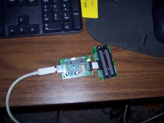
Better yet, all of those dead PIC16F628A chips weren't dead after all, so now I have LOTS of PIC chips! I've beem reprogramming them with good hex files and testing them. :-)
It was definitely something wrong either within the JDM board or the two PC's I tried to run it on didn't provide enough voltage to properly program PICs. I suspect that it was that last.
From what I've been able to read the USB port has a more reliable source of current that can tapped for programming than the RS232 port does.
As well, the new board uses a USB port which means I don't have to crawl around under my desk hooking up RS232 connectors any more.
Now I can see if I can get the motor controller routine and the serial comms routine working together on the motor controller board. It will also be fun to try to get the AS5035 magnetic enconder chip going, too. :-D
Happy Birthday to ME! :-D
Comments:
<< Home
If I remember the specs, they are supposed to be +-12v nominal, but +-3v to +-18v are all within spec.
That is why the +-5v use in lots of laptops are 'within spec'.
Yes, taking power from the serial port has always been a very iffy situation, but it has worked for some.
That is why the +-5v use in lots of laptops are 'within spec'.
Yes, taking power from the serial port has always been a very iffy situation, but it has worked for some.

Ah, Diego then, the Marines stationed there in the late 1980's used to come down to Mauritius for R&R.
Nope, I don't think that anybody uses the PICAXE system, which seems to be PIC chips wrapped up in a complete programming and prototyping package, rather like the BASIC Stamp microprocessor system that Parallex...
http://en.wikipedia.org/wiki/Parallax%2C_Inc._%28company%29
...makes.
PICAXE seems to be PIC chips with a boot programme to make things easy, something I was talking about our doing a few days ago in the project's internal correspondence.
We just use PIC chips straight. Most of the team use the SDCC compiler to program them. I use the PIC Simulator IDE system that has a BASIC compiler. It doesn't really matter what you use in that it's all hex code in the end.
I've been looking more closely at the PICAXE system. One could choose a LOT worse ways of getting into writing controls firmware than taking that route.
My first impression was that it was simply another BASIC Stamp wannabe which it resembles. On closer inspection, however, it appears to have a lot more going for it for an entry-level person insofar as having a user-friendly learning curve.
My first impression was that it was simply another BASIC Stamp wannabe which it resembles. On closer inspection, however, it appears to have a lot more going for it for an entry-level person insofar as having a user-friendly learning curve.
As a microcontroller newbie, I had bookmarked the PICAXE approach as one of the few best options out of a very wide range of microcontrollers out there. Actually, my short list at the moment is PIC, AVR, and PICAXE.
The AVR is in there because I might be able to more easily use some older Macs as programming machines.
The PIC is in there because it's so inexpensive, and once it's programming complexities are mastered it should pay of long term, sort of like the AVR.
I imagine the PICAXE as a sort of bridge between the two previous, and the easy yet expensive starting points of the BASIC Stamp and direct comptetitors.
I have to point out, my impression so far of the RepRap project is that the element that requires the largest knowledge base to use or modify is the PIC. Aside from that, it boils down to soldering fairly well, and being half decent at cobbling together assorted contraptions as per the project guidelines.
PICs are after all, pretty high end geek stuff...
A big part of my reason for getting into doing my own board design and firmware development was to personally demystify much of the "high end geek" feel of it.
My first notion was to get a more accessible language than C or Java. For that reason I went for BASIC, mostly because I know that for every Java or C programmer there are 50 people who have messed with BASIC at one time or another. Sadly, finding an inexpensive PIC BASIC compiler has been a trial to date. Most of them cost several hundred dollars. I'm hoping that Vladimir Soso's PIC Simulator IDE is going to sort that bit out.
The next bit is to either identify or create a good set of examples of how to do things in such a product.
Where you kind of jump ahead with PICAXE is that all of that seems already to have been done.
At the same time as jumping ahead with PICAXE, (oh my, that sounds precarious!) you also jump back a bit. Reviewing the data I'd collected on them I re-read that they can be very sloooow because of all that code in the. Arg. But still, they seem to be an excellent starting point.
But I agree, demystifying the high end geek stuff is fun, and what tends to draw me to projects, but it's not everyone's cup of tea.
There is also a big issue of persistance, everyone has their own comfort level. Or should that be "discomfort level"!
In any case, if I understand the big idea of the RepRap project, I think it is safe to say the PICs are the largest stumbling block to wider adoption. So as long as that is factored in, in a realistic and effective way, it should work.
Post a Comment
But I agree, demystifying the high end geek stuff is fun, and what tends to draw me to projects, but it's not everyone's cup of tea.
There is also a big issue of persistance, everyone has their own comfort level. Or should that be "discomfort level"!
In any case, if I understand the big idea of the RepRap project, I think it is safe to say the PICs are the largest stumbling block to wider adoption. So as long as that is factored in, in a realistic and effective way, it should work.
<< Home
![]()